

ST M40SZ100Y, M40SZ100W User Manual
M40SZ100Y
M40SZ100W
5 V or 3 V NVRAM supervisor for LPSRAM
Features
■ Convert low power SRAMs into NVRAMs
■ 5 V or 3 V operating voltage
■ Precision power monitoring and power
switching circuitry
■ Automatic write-protection when V
tolerance
■ Choice of supply voltages and power-fail
deselect voltages:
– M40SZ100Y: V
4.20 V ≤ V
PFD
= 4.5 to 5.5 V;
CC
≤ 4.50 V
(contact local ST sales office for
availability)
– M40SZ100W: V
2.55 V ≤ V
■ Reset output (RST) for power on reset
■ 1.25 V reference (for PFI/PFO)
■ Less than 10 ns chip enable access
PFD
= 2.7 to 3.6 V;
CC
≤ 2.70 V
propagation delay (at 5 V)
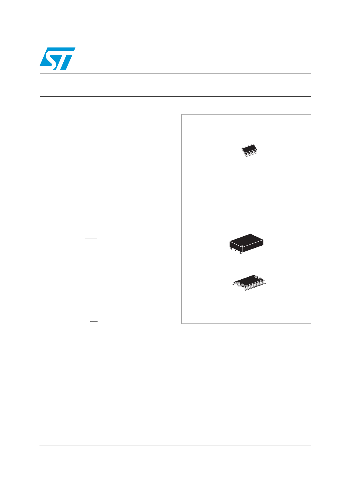
■ Optional packaging includes a 28-lead SOIC
and SNAPHAT
■ 28-lead SOIC package provides direct
®
top (to be ordered separately)
connection for a SNAPHAT top which contains
the battery (contact local ST sales office for
availability)
■ Battery low pin (BL)
■ RoHS compliant
– Lead-free second level interconnect
is out-of-
CC
16
1
SO16 (MQ)
SNAPHAT (SH) battery
28
1
SOH28 (MH)
October 2010 Doc ID 7528 Rev 3 1/24
www.st.com
1

Contents M40SZ100Y, M40SZ100W
Contents
1 Description . . . . . . . . . . . . . . . . . . . . . . . . . . . . . . . . . . . . . . . . . . . . . . . . . 5
2 Operation . . . . . . . . . . . . . . . . . . . . . . . . . . . . . . . . . . . . . . . . . . . . . . . . . . 9
2.1 Data retention lifetime calculation . . . . . . . . . . . . . . . . . . . . . . . . . . . . . . . 9
2.2 Power-on reset output . . . . . . . . . . . . . . . . . . . . . . . . . . . . . . . . . . . . . . . 12
2.3 Reset input (RSTIN
2.4 Battery low pin . . . . . . . . . . . . . . . . . . . . . . . . . . . . . . . . . . . . . . . . . . . . . 12
2.5 Power-fail input/output . . . . . . . . . . . . . . . . . . . . . . . . . . . . . . . . . . . . . . . 13
2.6 V
noise and negative going transients . . . . . . . . . . . . . . . . . . . . . . . . . 13
CC
) . . . . . . . . . . . . . . . . . . . . . . . . . . . . . . . . . . . . . . . . . 12
3 Maximum ratings . . . . . . . . . . . . . . . . . . . . . . . . . . . . . . . . . . . . . . . . . . . 15
4 DC and AC parameters . . . . . . . . . . . . . . . . . . . . . . . . . . . . . . . . . . . . . . 16
5 Package mechanical data . . . . . . . . . . . . . . . . . . . . . . . . . . . . . . . . . . . . 18
6 Part numbering . . . . . . . . . . . . . . . . . . . . . . . . . . . . . . . . . . . . . . . . . . . . 22
7 Revision history . . . . . . . . . . . . . . . . . . . . . . . . . . . . . . . . . . . . . . . . . . . 23
2/24 Doc ID 7528 Rev 3

M40SZ100Y, M40SZ100W List of tables
List of tables
Table 1. Signal names . . . . . . . . . . . . . . . . . . . . . . . . . . . . . . . . . . . . . . . . . . . . . . . . . . . . . . . . . . . . 6
Table 2. Power down/up AC characteristics . . . . . . . . . . . . . . . . . . . . . . . . . . . . . . . . . . . . . . . . . . . 11
Table 3. Reset AC characteristics . . . . . . . . . . . . . . . . . . . . . . . . . . . . . . . . . . . . . . . . . . . . . . . . . . 12
Table 4. Absolute maximum ratings . . . . . . . . . . . . . . . . . . . . . . . . . . . . . . . . . . . . . . . . . . . . . . . . . 15
Table 5. DC and AC measurement conditions . . . . . . . . . . . . . . . . . . . . . . . . . . . . . . . . . . . . . . . . . 16
Table 6. Capacitance . . . . . . . . . . . . . . . . . . . . . . . . . . . . . . . . . . . . . . . . . . . . . . . . . . . . . . . . . . . . 16
Table 7. DC characteristics. . . . . . . . . . . . . . . . . . . . . . . . . . . . . . . . . . . . . . . . . . . . . . . . . . . . . . . . 17
Table 8. SO16 – 16-lead plastic small outline package mechanical data. . . . . . . . . . . . . . . . . . . . . 18
Table 9. SOH28 – 28-lead plastic small outline, battery SNAPHAT, pack. mech. data . . . . . . . . . . 19
Table 10. SH – 4-pin SNAPHAT housing for 48 mAh battery, package mechanical data . . . . . . . . . 20
Table 11. SH – 4-pin SNAPHAT housing for 120 mAh battery, package mechanical data . . . . . . . . 21
Table 12. Ordering information scheme . . . . . . . . . . . . . . . . . . . . . . . . . . . . . . . . . . . . . . . . . . . . . . . 22
Table 13. SNAPHAT
Table 14. Document revision history . . . . . . . . . . . . . . . . . . . . . . . . . . . . . . . . . . . . . . . . . . . . . . . . . 23
®
battery table . . . . . . . . . . . . . . . . . . . . . . . . . . . . . . . . . . . . . . . . . . . . . . . . . . 22
Doc ID 7528 Rev 3 3/24

List of figures M40SZ100Y, M40SZ100W
List of figures
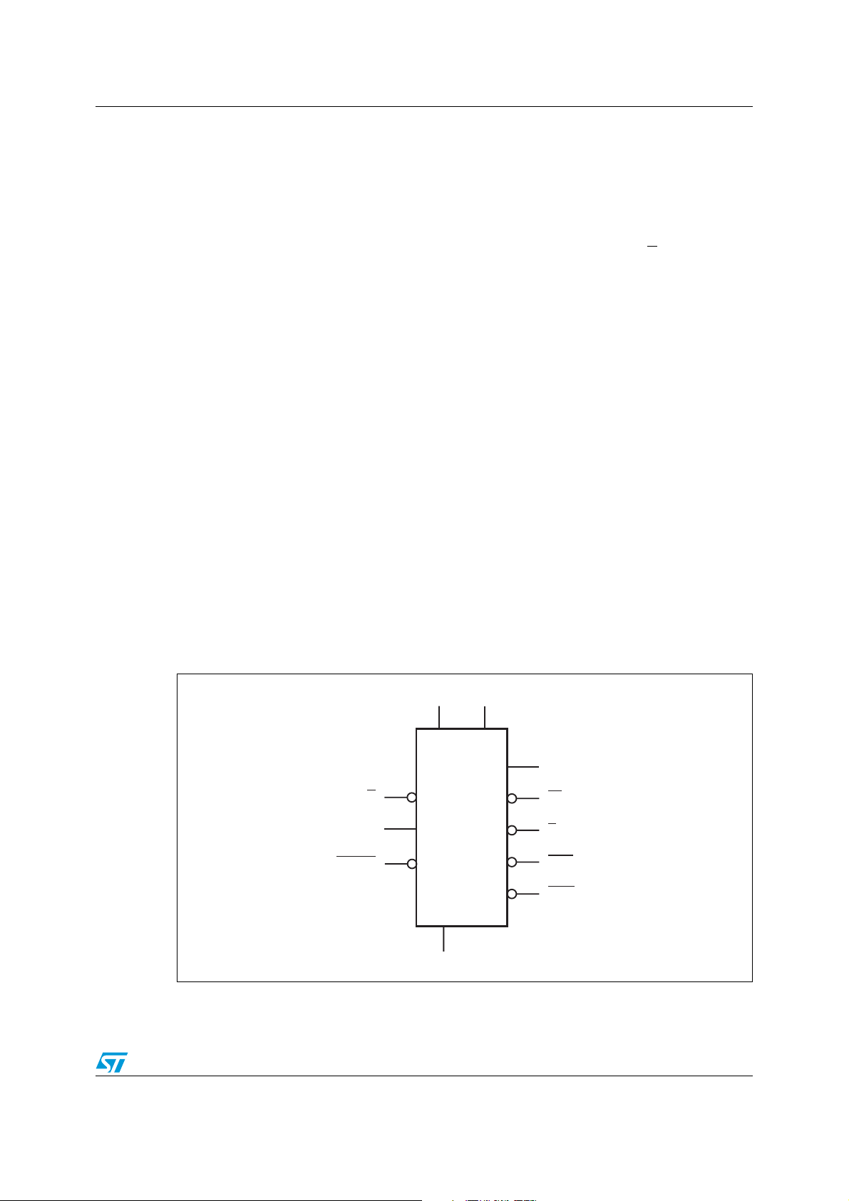
Figure 1. Logic diagram . . . . . . . . . . . . . . . . . . . . . . . . . . . . . . . . . . . . . . . . . . . . . . . . . . . . . . . . . . . . 5
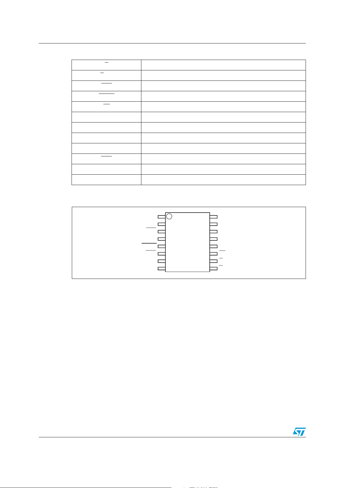
Figure 2. SOIC16 connections . . . . . . . . . . . . . . . . . . . . . . . . . . . . . . . . . . . . . . . . . . . . . . . . . . . . . . . 6
Figure 3. SOIC28 connections . . . . . . . . . . . . . . . . . . . . . . . . . . . . . . . . . . . . . . . . . . . . . . . . . . . . . . . 7
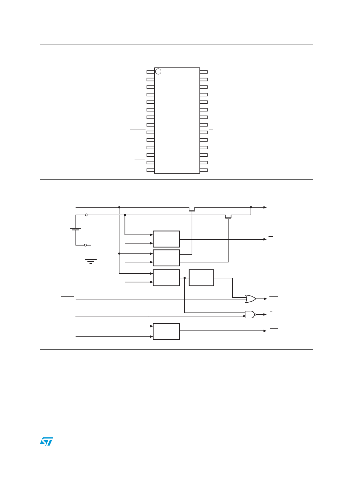
Figure 4. Block diagram . . . . . . . . . . . . . . . . . . . . . . . . . . . . . . . . . . . . . . . . . . . . . . . . . . . . . . . . . . . . 7
Figure 5. Hardware hookup . . . . . . . . . . . . . . . . . . . . . . . . . . . . . . . . . . . . . . . . . . . . . . . . . . . . . . . . . 8
Figure 6. Power down timing . . . . . . . . . . . . . . . . . . . . . . . . . . . . . . . . . . . . . . . . . . . . . . . . . . . . . . . 10
Figure 7. Power up timing . . . . . . . . . . . . . . . . . . . . . . . . . . . . . . . . . . . . . . . . . . . . . . . . . . . . . . . . . 11
Figure 8. RSTIN
Figure 9. Supply voltage protection . . . . . . . . . . . . . . . . . . . . . . . . . . . . . . . . . . . . . . . . . . . . . . . . . . 14
Figure 10. AC testing load circuit . . . . . . . . . . . . . . . . . . . . . . . . . . . . . . . . . . . . . . . . . . . . . . . . . . . . . 16
Figure 11. AC testing input/output waveforms . . . . . . . . . . . . . . . . . . . . . . . . . . . . . . . . . . . . . . . . . . . 16
Figure 12. SO16 – 16-lead plastic small package outline . . . . . . . . . . . . . . . . . . . . . . . . . . . . . . . . . . 18
Figure 13. SOH28 – 28-lead plastic small outline, 4-socket battery SNAPHAT, package outline . . . . 19
Figure 14. SH – 4-pin SNAPHAT housing for 48 mAh battery, package outline . . . . . . . . . . . . . . . . . 20
Figure 15. SH – 4-pin SNAPHAT housing for 120 mAh battery, package outline . . . . . . . . . . . . . . . . 21
timing waveform . . . . . . . . . . . . . . . . . . . . . . . . . . . . . . . . . . . . . . . . . . . . . . . . . . . 12
4/24 Doc ID 7528 Rev 3
M40SZ100Y, M40SZ100W Description
1 Description
The M40SZ100Y/W NVRAM controller is a self-contained device which converts a standard
low-power SRAM into a non-volatile memory. A precision voltage reference and comparator
monitors the V
When an invalid V
inactive to write protect the stored data in the SRAM. During a power failure, the SRAM is
switched from the V
the 16-lead SOIC) to provide the energy required for data retention. On a subsequent
power-up, the SRAM remains write protected until a valid power condition returns.
input for an out-of-tolerance condition.
CC
condition occurs, the conditioned chip enable output (E
CC
pin to the lithium cell within the SNAPHAT® (or external battery for
CC
) is forced
CON
The 28-pin, 330 mil SOIC provides sockets with gold plated contacts for direct connection to
a separate SNAPHAT
®
housing containing the battery. The SNAPHAT housing has gold
plated pins which mate with the sockets, ensuring reliable connection. The housing is keyed
to prevent improper insertion. This unique design allows the SNAPHAT battery package to
be mounted on top of the SOIC package after the completion of the surface mount process
which greatly reduces the board manufacturing process complexity of either directly
soldering or inserting a battery into a soldered holder. Providing non-volatility becomes a
“SNAP.” This feature is also available in the “topless” 16-pin SOIC package (MQ).
Insertion of the SNAPHAT housing after reflow prevents potential battery damage due to the
high temperatures required for device surface-mounting. The SNAPHAT housing is also
keyed to prevent reverse insertion.
The 28-pin SOIC and battery packages are shipped separately in plastic anti-static tubes or
in tape & reel form. For the 28-lead SOIC, the battery/crystal package (e.g., SNAPHAT) part
number is M4Z28-BR00SH (for 48 mAh battery)
or M4Z32-BR00SH (for 120 mAh battery).
Caution: Do not place the SNAPHAT battery top in conductive foam, as this will drain the lithium
button-cell battery.
Figure 1. Logic diagram
(1)
V
V
CC
BAT
RSTIN
1. For 16-pin SOIC package only.
V
OUT
E
PFI
Doc ID 7528 Rev 3 5/24
M40SZ100Y
M40SZ100W
V
SS
BL
E
CON
PFO
RST
AI03933
Description M40SZ100Y, M40SZ100W
Table 1. Signal names
E Chip enable input
E
CON
Conditioned chip enable output
RST Reset output (open drain)
RSTIN Reset input
BL Battery low output (open drain)
V
V
V
BAT
OUT
CC
(1)
Supply voltage output
Supply voltage
Backup supply voltage
PFI Power fail input
PFO Power fail output
V
SS
Ground
NC Not connected internally
1. For SO16 only.
Figure 2. SOIC16 connections
NC
NC
RST
NC
RSTIN
PFO
V
BAT
V
SS
V
1
2
3
4
M40SZ100Y
M40SZ100W
5
6
710
8
16
15
14
13
12
11
CC
NC
V
OUT
NC
PFI
BL
E
9
E
CON
AI03935
6/24 Doc ID 7528 Rev 3
M40SZ100Y, M40SZ100W Description
Figure 3. SOIC28 connections
Figure 4. Block diagram
V
CC
V
BAT
BL
NC
NC
NC
NC
NC
NC
NC
RSTIN
NC
NC
PFO
V
SS
VBL= 2.5V
1
2
3
4
5
6
7
M40SZ100Y
M40SZ100W
8
9
10
11
12
13
14
COMPARE
28
27
26
25
24
23
22
21
20
19
18
17
16
15
V
CC
NC
NC
V
OUT
NC
NC
PFI
NC
E
NC
RST
NCNC
NC
E
CON
V
BL
AI03934
OUT
(1)
RSTIN
E
PFI
1.25V
1. Open drain output
V
V
PFD
= 2.5V
SO
= 4.4V
(2.65V for SZ100W)
COMPARE
COMPARE
COMPARE
POR
RST
E
CON
PFO
(1)
AI04766
Doc ID 7528 Rev 3 7/24
Description M40SZ100Y, M40SZ100W
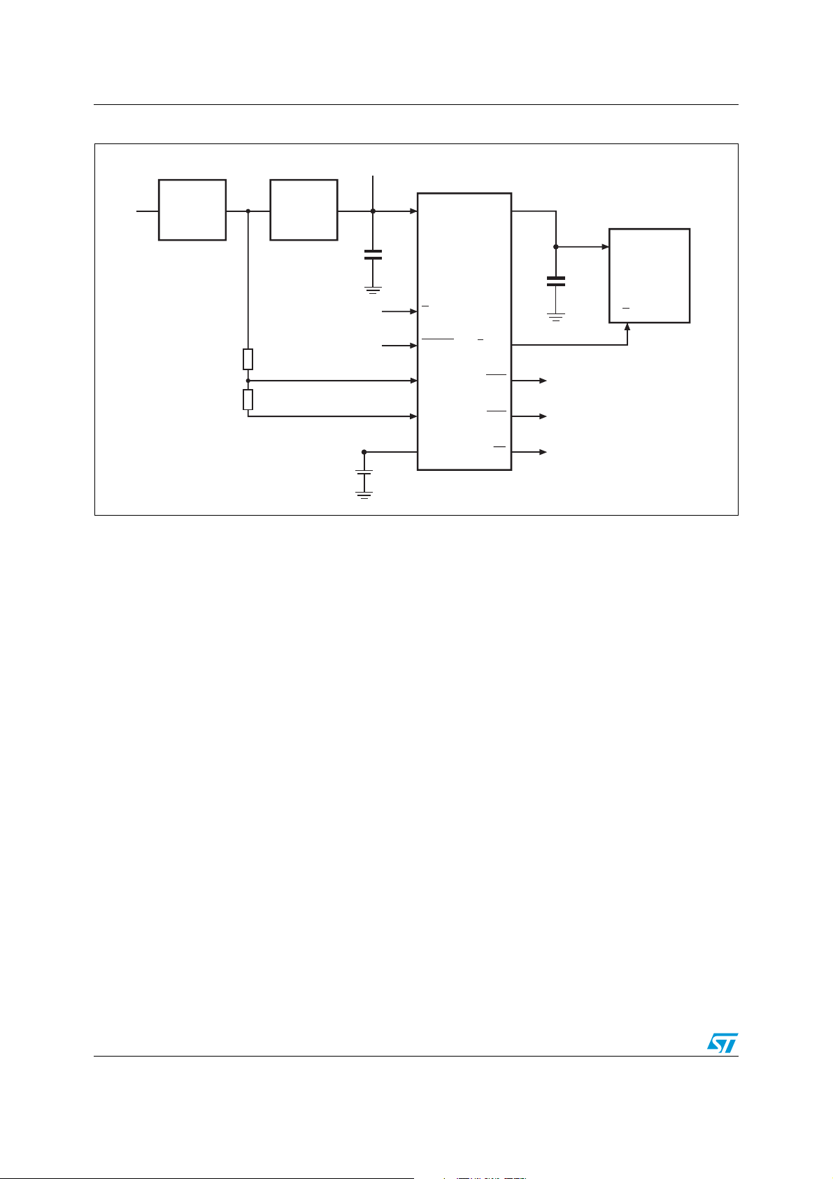
Figure 5. Hardware hookup
3.0V, 3.3V or 5V
Unregulated
Voltage
R1
R2
Regulator
V
IN
1. User supplied for the 16-pin package
V
CC
0.1µF
From Microprocessor
V
CC
E
RSTIN
PFI
V
SS
V
BAT
V
OUT
M40SZ100Y
M40SZ100W
E
CON
PFO
RST
(1)
BL
V
CC
0.1µF
To Microprocessor NMI
To Microprocessor Reset
To Battery Monitor Circuit
1Mb or 4Mb
LPSRAM
E
AI04767
8/24 Doc ID 7528 Rev 3
 Loading...