How it Works
Log In / Sign Up
Buy Points
How it Works
FAQ
Contact Us
Questions and Suggestions
Users
ST
Loading...
L
LD39300
LD3980
LD49150PT08R
LD49150PT10R
LD49150PT12R
LD49150PU10R
LD49150PU12R
LD49300PT08R
LD49300PT10R
LD49300PT12R
LDCL015M33R
LDCL015MR
LDLN015PU10R
LDLN015PU12R
LDLN015PU15R
LDLN015PU18R
LDLN015PU28R
LDLN015PU33R
LDS3985M125R
LDS3985M135R
LDS3985M15R
LDS3985M18R
LDS3985M20R
LDS3985M21R
LDS3985M22R
LDS3985M25R
LDS3985M26R
LDS3985M27R
LDS3985M285R
LDS3985M28R
LDS3985M29R
LDS3985M30R
LDS3985M33R
LDS3985M47R
LDS3985M48R
LDS3985M49R
LDS3985M50R
LDS3985PM12R
LE30CD-TR
LE33CD-TR
LE33CZ-AP
LE33CZ-TR
LE45CD-TR
LE50ABD-TR
LE50ABZ-AP
LE50CD-TR
LE80CD-TR
LED2000
LED7706
LED7707
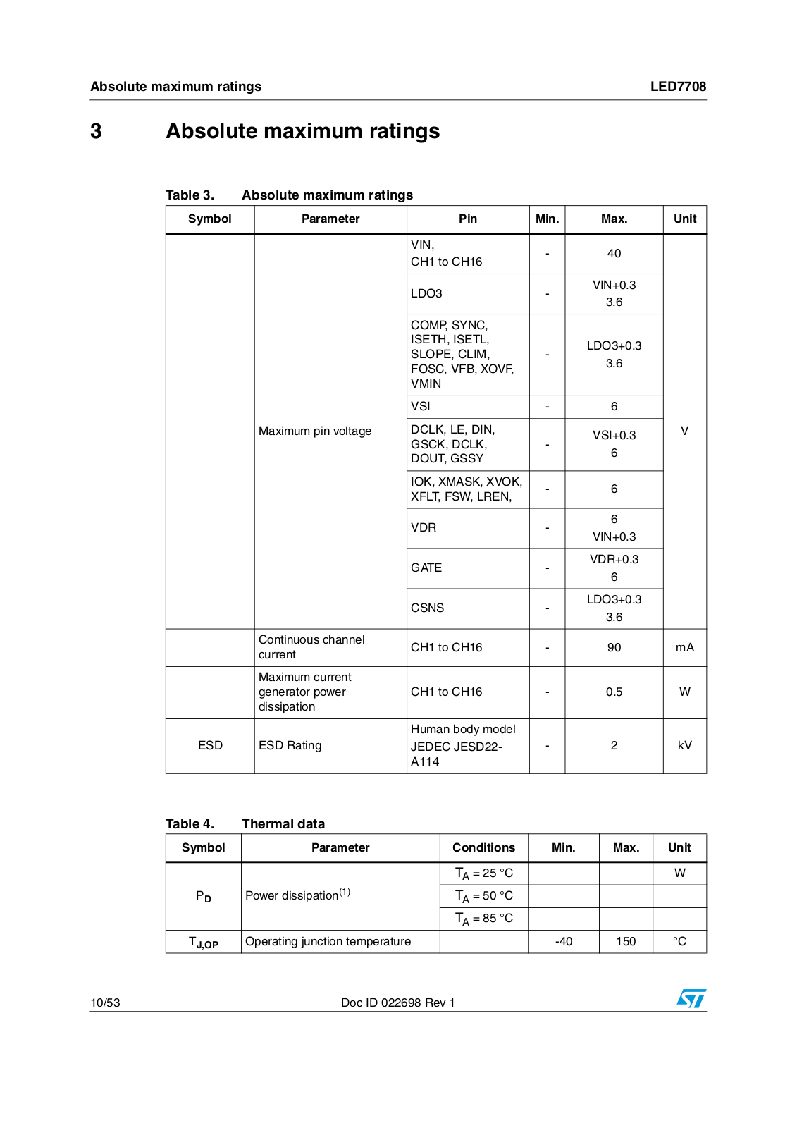
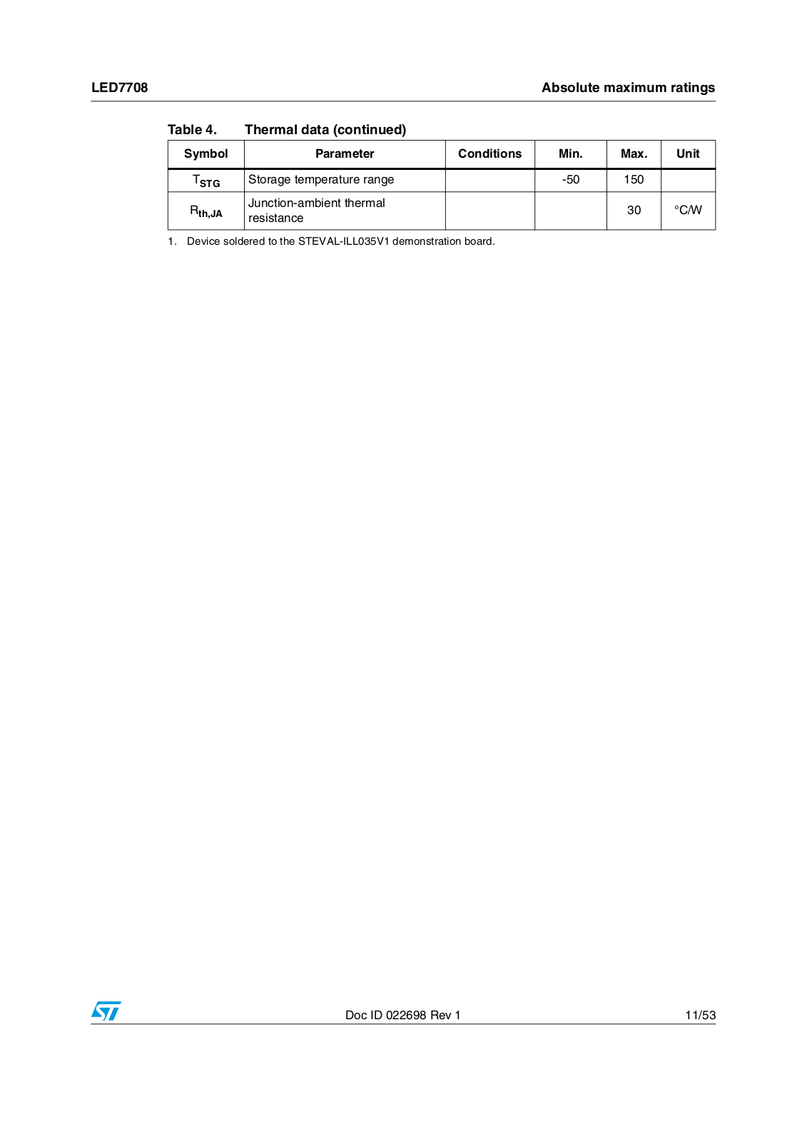
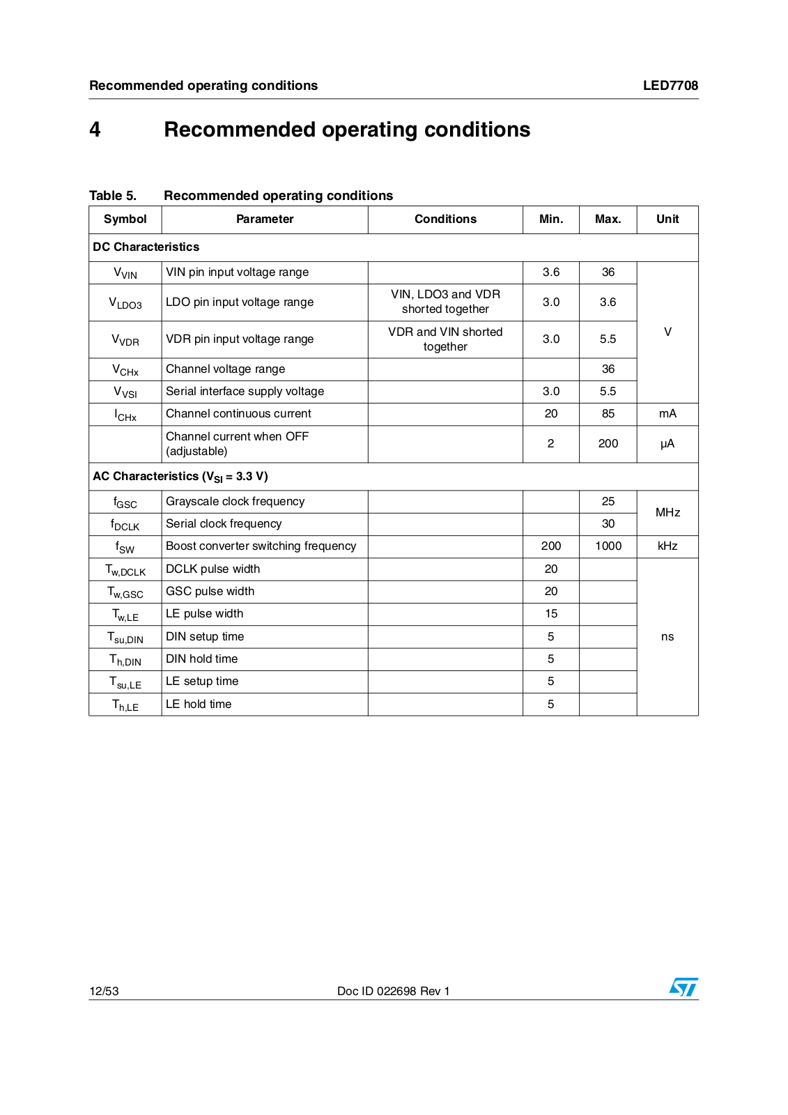
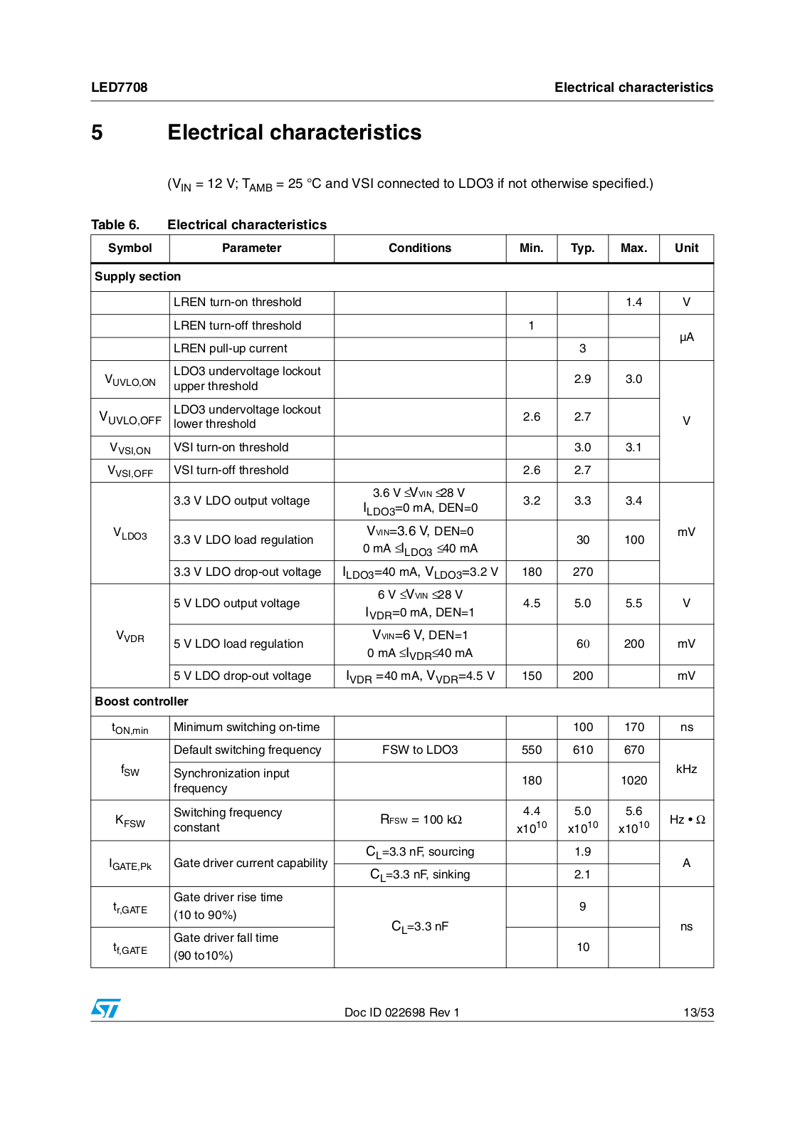
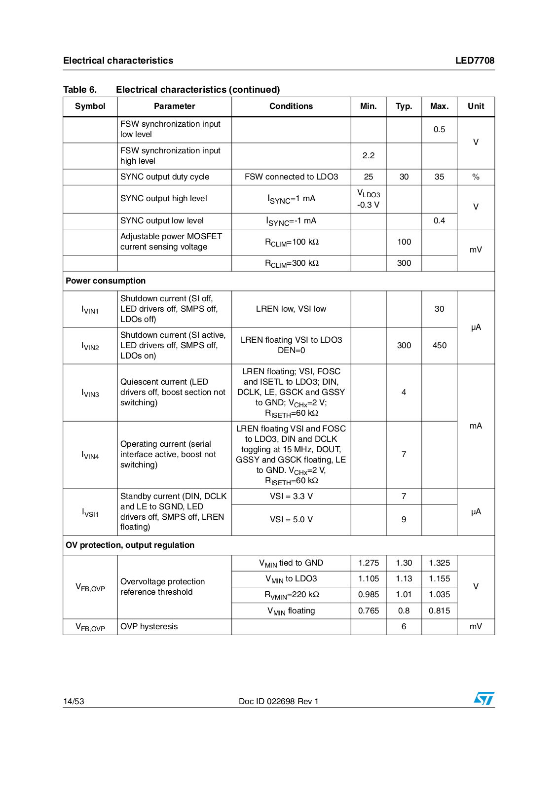
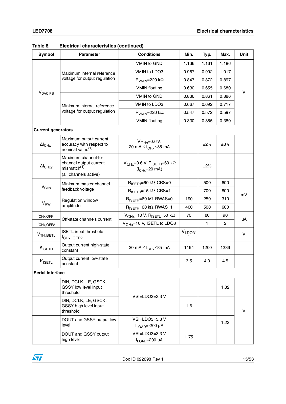
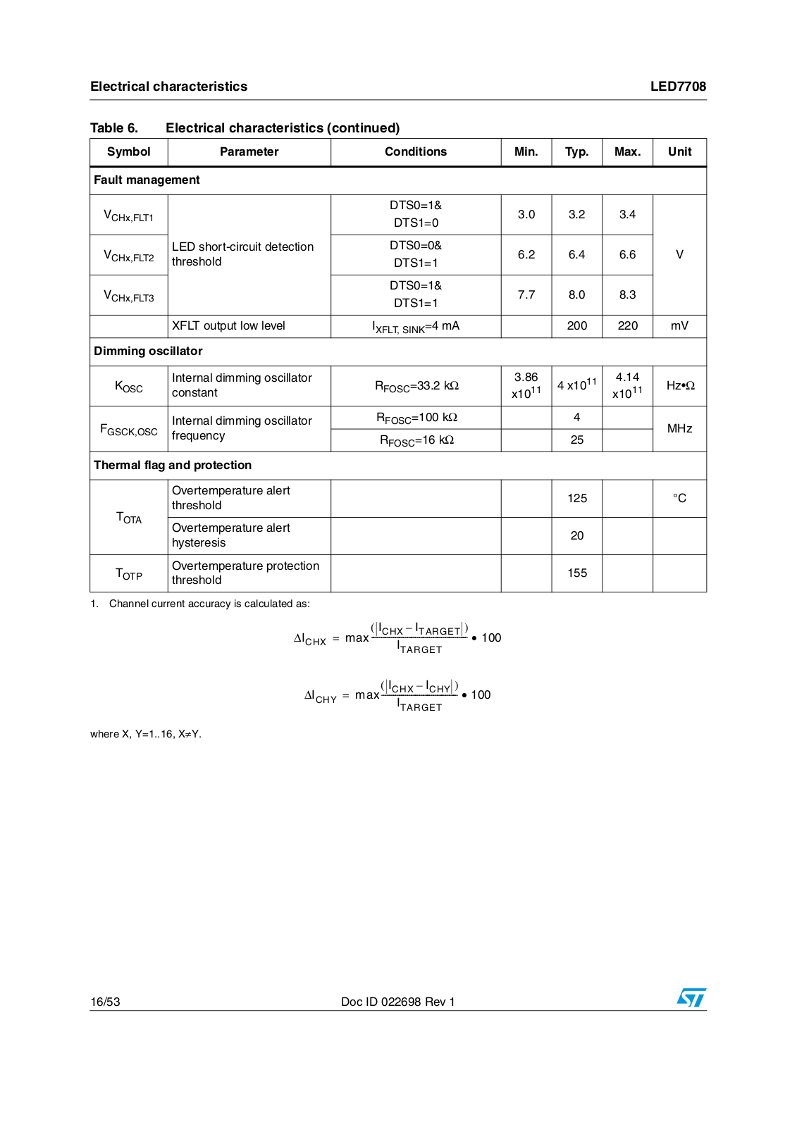
LED7708
LEQ ARACHNE
LET9060C
LF00
LF147
LF247
LF253
LF347
LF351
LF353
LI3
LIC01
LIS2DH
LIS2DM
LIS2DW12
LIS302DL
LIS331DL
LIS331DLH
LIS331DLM
LIS331HH
LIS332AR
LIS332AX
LIS344ALH
LIS352AR
LIS352AX
LIS3DH
LIS3DSH
LIS3LV02DL
LK112M15TR
LK112M18TR
LK112M19TR
LK112M20TR
LK112M22TR
LK112M23TR
LK112M24TR
LK112M25TR
LK112M26TR
LK112M29TR
LK112M31TR
LK112M33TR
LK112M34TR
LK112M35TR
LK112M37TR
LK112M39TR
LK112M41TR
LK112M42TR
LK112M43TR
LK112M44TR
LK112M45TR
LK112M46TR
Loading...
Loading...
Nothing found
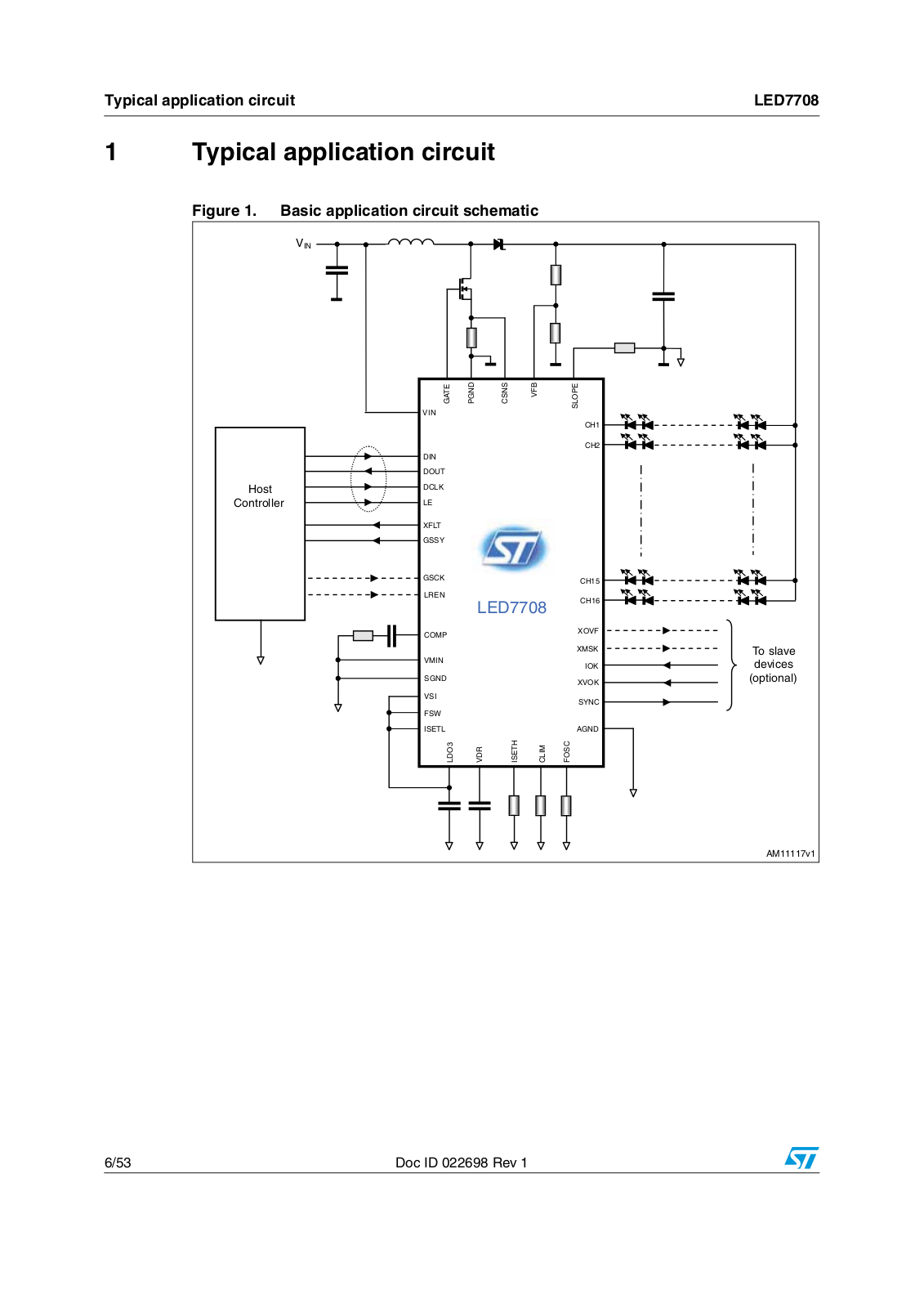
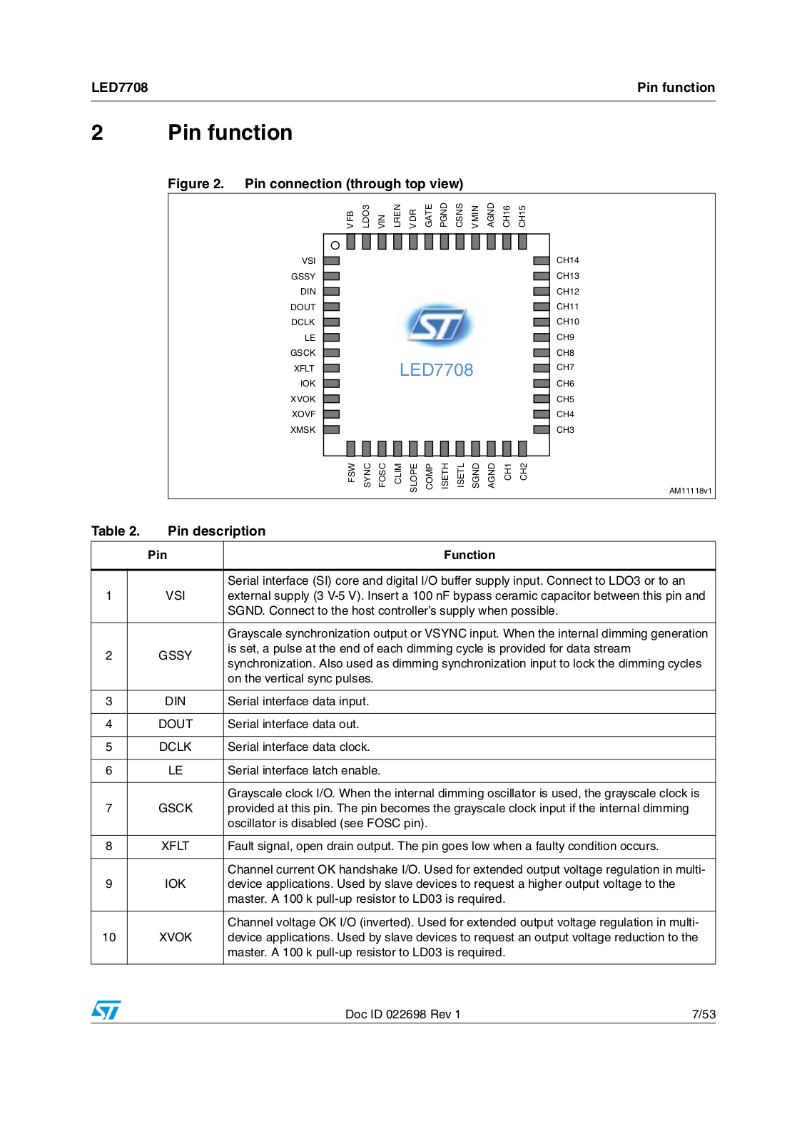
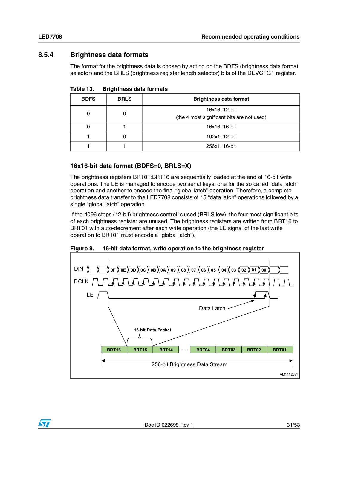
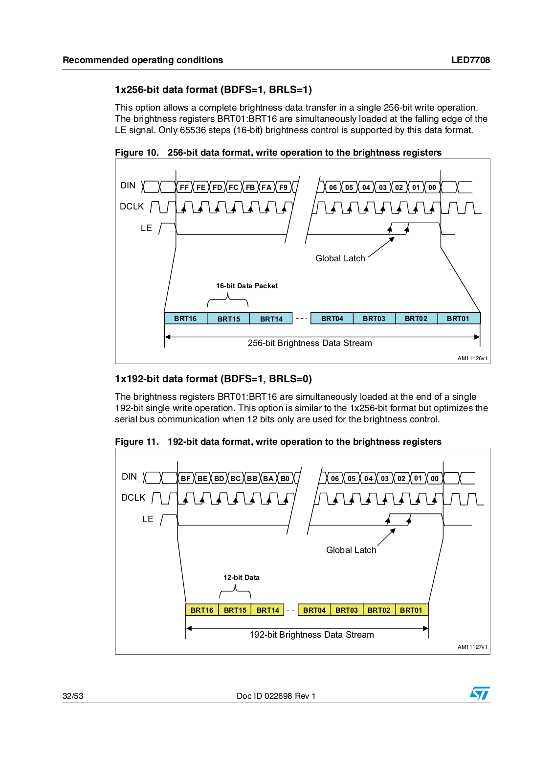
LED7708
User Manual
53 pgs
875.94 Kb
0
Table of contents
Loading...
ST LED7708 User Manual
...
ST User Manual
Download
Specifications and Main Features
Frequently Asked Questions
User Manual
Download
Loading...
+
hidden pages
Unhide
You need points to download manuals.
1 point = 1 manual.
You can buy points or you can get point for every manual you upload.
Buy points
Upload your manuals
 Loading...