

ST L9951 User Manual
1 FEATURES
Tabl
■ One half bridge for 7.4A load (r
■ Two half bridges for 5A load (r
■
Two highside drivers for 1.25A load (ron = 800 mΩ)
■ Programmable Softstart function to drive loads
= 150mΩ)
on
= 200mΩ)
on
with higher inrush currents (i.e.current >7.4A,
>5A, >1.25A)
■ Very low current consumption in standby mode
(I
< 3µA, typ. Tj ≤ 85 °C)
S
■ All outputs short circuit protected
■ Current monitor output for all highside drivers
■ All outputs over temperature protected
■ Open load diagnostic for all outputs
■ Overload diagnostic for all outputs
■ Programmable PWM control of all outputs
■ Charge Pump output for reverse polarity
protection
2 APPLICATION
■ Rear Door Actuator Driver with bridges for door
lock and safe lock and two 5W or 10W-light
bulbs.
L9951
DOOR ACTUATOR DRIVER
DATA BRIEF
PowerSO36
e 1. Order Codes
Part Number Package
L9951 PowerSO36
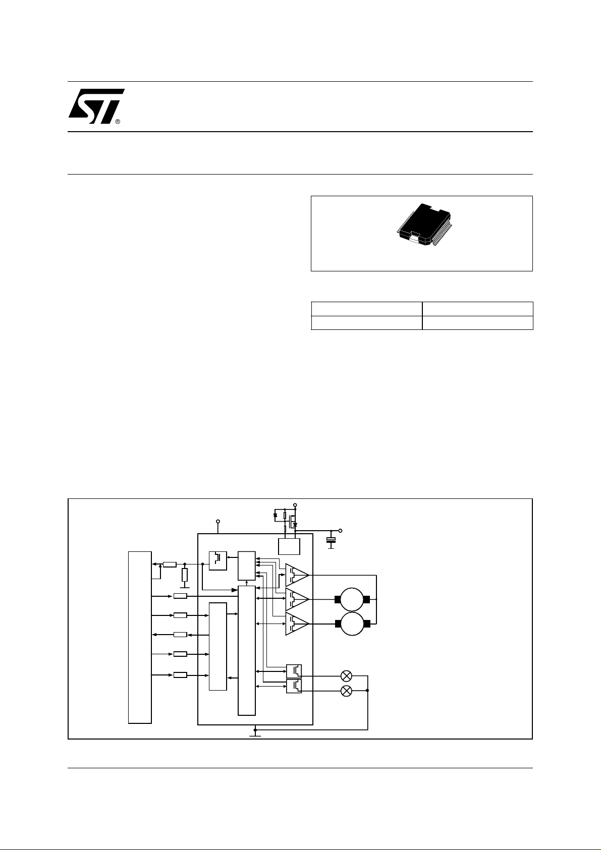
3 DESCRIPTION
The L9951 is a microcontroller driven multifunctional rear door actuat or driver fo r automoti ve applications. Up to two DC motors and two grounded
resistive loads can be dr iven with thr ee hal f br idg es and two highsi de drivers. T he integrated standard serial peripheral interface (SPI) controls all
operation modes (forward, reverse, brake and
high impedance). All diagnostic information s are
available via SPI.
BLOCK DIAGRAM
VBAT
Reverse
100k
10k
CP
Polarity
Protection
OUT1
OUT2
OUT3
OUT4
OUT5
VS
Note: value of capacitor has to be choosen
carefully to limit the VS voltage below abs olute
maximum ratings in case of an unexpected
freewheeling condition (e.g. TSD, POR)
Lock
M
M
Safe Lock
Exteriour Light
Safety Light
µC
CM/PWM
PWM
EN
DI
DO
CLK
CSN
VCC
MUX
SPI
Driver Interface & Diagno stic
GND
April 2004
This is preliminary information on a new product now in development. Details are subject to change without notice.
REV. 2
1/4
L9951
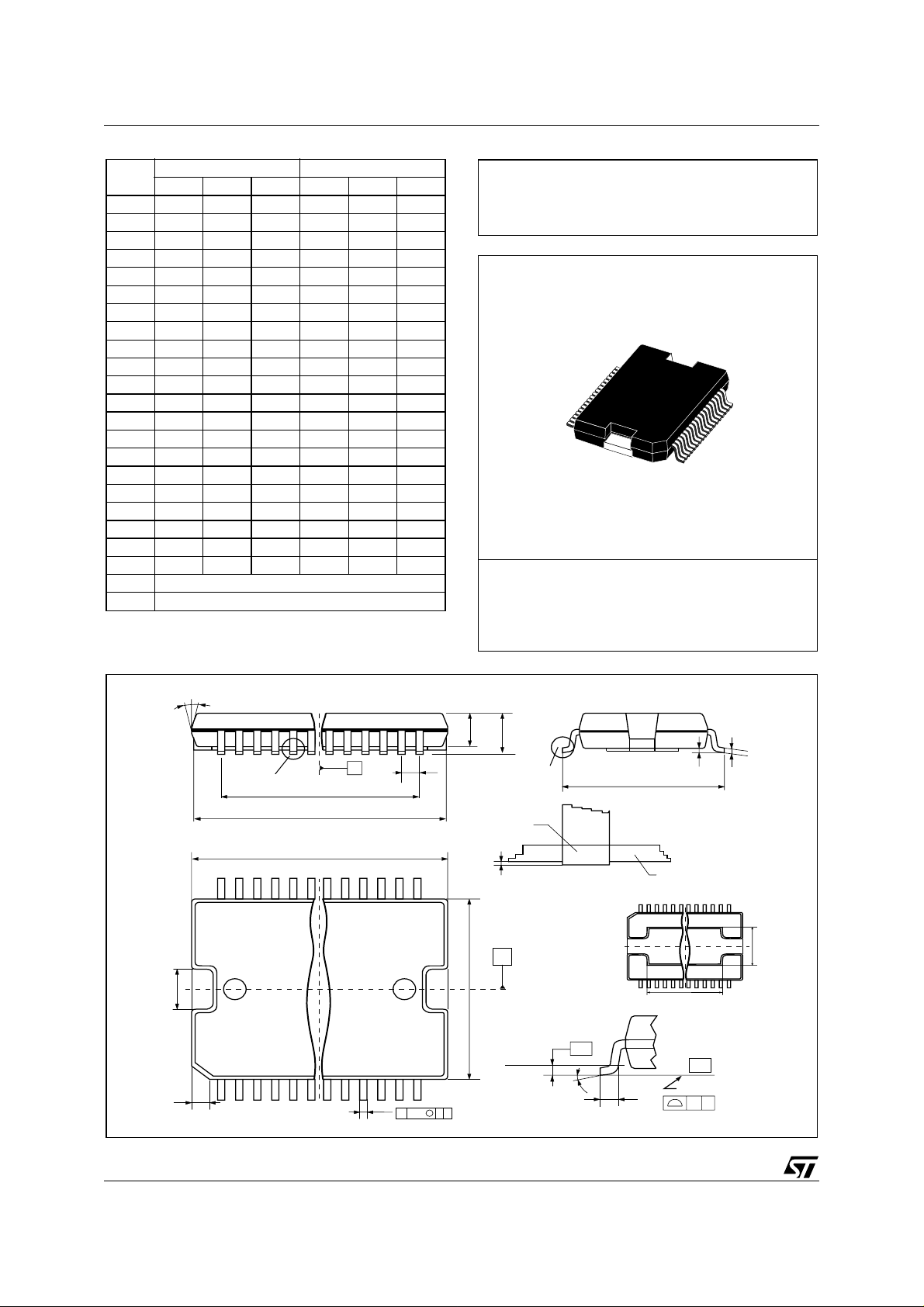
DIM.
MIN. TYP. MAX. MIN. TYP. MAX.
mm inch
A 3.25 3.5 0.128 0.138
A2 3.3 0.13
A4 0.8 1 0.031 0.039
A5 0.2 0.008
a100.07500.003
b 0.22 0.38 0.008 0.015
c 0.23 0.32 0.009 0.012
D 15.8 16 0.622 0.630
D1 9.4 9.8 0.37 0.38
D2 1 0.039
E 13.9 14.5 0.547 0.57
E1 10.9 11.1 0.429 0.437
E2 2.9 0.114
E3 5.8 6.2 0.228 0.244
E4 2.9 3.2 0.114 1.259
e 0.65 0.026
e3 11.05 0.435
G 0 0.075 0 0.003
H 15.5 15.9 0.61 0.625
h 1.1 0.043
L 0.8 1.1 0.031 0.043
N 10˚ (max)
s 8˚ (max)
Note: “D a nd E1” do not incl ude mold flash or protusions.
- Mold flash or protusions shall not exceed 0.15mm (0.006”)
- Critical dim ensions ar e " a3" , " E" and "G".
OUTLINE AND
MECHANICAL DA TA
PowerSO36
E2
h x 45
NN
a2
DETAIL A
118
A
e3
H
D
b
e
1936
M
0.12 AB
E1
A
DETAIL B
a3
B
Gage Plane
PSO36MEC
lead
BOTTOM VIEW
DETAIL B
S
0.35
DETAIL A
L
E
slug
(COPLANARITY)
c
a1
E3
D1
- C -
SEATING PLANE
GC
0096119 B
2/4
 Loading...