

Page 1
Octal configurable low/high side driver
Features
■ Configurable up to 6 high side drivers
■ R
■ Current limit of each output at min. 0.8 A
■ Supply voltage 4.75 V to 5.25 V
■ Output voltage clamping min. 35 V (low side
mode)
■ Output voltage clamping -30 V (high side
mode)
■ SPI interface for data communication
■ Additional PWM inputs for 2 outputs
■ Thermal shutdown for all outputs
■ Open load detection in off mode
■ Reverse battery protection for outputs (amb)
■ Ground disconnection for high side configured
outputs
Description
The L9848 IC is a highly flexible monolithic
medium current output driver that incorporates 2
dedicated low side outputs (outputs 7-8) and 6
outputs that can be used as either internal low or
high side drives in any combination (outputs 1-6).
Table 1. Device summary
= max.1.5 Ω @ Tj = 25 °C
DSON
L9848
SO-28
In addition, 2 outputs are capable of being
PWMed via an external pin (outputs 5-6). The
integrated standard serial peripheral interface
(SPI) controls all outputs and provides diagnostic
information.
Integrated clamping circuits, waveshaping,
protection against positive and negative voltage
transients and thermal shutdown for all outputs
open a wide range of automotive and industrial
applications
Order code Package Packing
L9848 SO-28 Tube
November 2008 Rev 5 1/27
www.st.com
1
Page 2

Contents L9848
Contents
1 Block diagram and pin description . . . . . . . . . . . . . . . . . . . . . . . . . . . . . 6
2 Electrical specifications . . . . . . . . . . . . . . . . . . . . . . . . . . . . . . . . . . . . . . 8
2.1 Absolute maximum ratings . . . . . . . . . . . . . . . . . . . . . . . . . . . . . . . . . . . . . 8
2.2 Operation conditions . . . . . . . . . . . . . . . . . . . . . . . . . . . . . . . . . . . . . . . . . 8
2.3 Thermal data . . . . . . . . . . . . . . . . . . . . . . . . . . . . . . . . . . . . . . . . . . . . . . . 9
2.4 Electrical characteristcs . . . . . . . . . . . . . . . . . . . . . . . . . . . . . . . . . . . . . . . 9
2.4.1 DC characteristics . . . . . . . . . . . . . . . . . . . . . . . . . . . . . . . . . . . . . . . . . . 9
2.4.2 AC characteristics . . . . . . . . . . . . . . . . . . . . . . . . . . . . . . . . . . . . . . . . . 11
3 Functional description . . . . . . . . . . . . . . . . . . . . . . . . . . . . . . . . . . . . . . 14
3.1 General features . . . . . . . . . . . . . . . . . . . . . . . . . . . . . . . . . . . . . . . . . . . . 14
3.2 Outputs - Common characteristics . . . . . . . . . . . . . . . . . . . . . . . . . . . . . 14
3.2.1 Output 1-4 . . . . . . . . . . . . . . . . . . . . . . . . . . . . . . . . . . . . . . . . . . . . . . . 14
3.2.2 Output 5-6 . . . . . . . . . . . . . . . . . . . . . . . . . . . . . . . . . . . . . . . . . . . . . . . 15
3.2.3 Output7-8 . . . . . . . . . . . . . . . . . . . . . . . . . . . . . . . . . . . . . . . . . . . . . . . . 15
3.3 Main power input (VDD) . . . . . . . . . . . . . . . . . . . . . . . . . . . . . . . . . . . . . . 15
3.4 Discrete inputs (IN5-6) . . . . . . . . . . . . . . . . . . . . . . . . . . . . . . . . . . . . . . . 15
3.5 Serial peripheral interface (SPI) . . . . . . . . . . . . . . . . . . . . . . . . . . . . . . . . 15
3.5.1 Serial data output (DO) . . . . . . . . . . . . . . . . . . . . . . . . . . . . . . . . . . . . . 16
3.5.2 Serial data input (DI) . . . . . . . . . . . . . . . . . . . . . . . . . . . . . . . . . . . . . . . 16
3.5.3 Chip select (CS) . . . . . . . . . . . . . . . . . . . . . . . . . . . . . . . . . . . . . . . . . . . 16
3.5.4 Serial clock (SCLK) . . . . . . . . . . . . . . . . . . . . . . . . . . . . . . . . . . . . . . . . 16
3.6 SPI DI input command register . . . . . . . . . . . . . . . . . . . . . . . . . . . . . . . . 17
3.7 Fault operation . . . . . . . . . . . . . . . . . . . . . . . . . . . . . . . . . . . . . . . . . . . . . 17
3.7.1 Initial fault register SPI Cycle . . . . . . . . . . . . . . . . . . . . . . . . . . . . . . . . . 18
3.7.2 Incandescent lamp outputs . . . . . . . . . . . . . . . . . . . . . . . . . . . . . . . . . . 18
3.8 Configuration for Output1-6 . . . . . . . . . . . . . . . . . . . . . . . . . . . . . . . . . . . 18
3.8.1 Low side drivers . . . . . . . . . . . . . . . . . . . . . . . . . . . . . . . . . . . . . . . . . . . 18
3.8.2 High side drivers . . . . . . . . . . . . . . . . . . . . . . . . . . . . . . . . . . . . . . . . . . 18
3.9 DRN1-6 susceptibility to negative voltage transients . . . . . . . . . . . . . . . . 18
3.10 Thermal shutdown . . . . . . . . . . . . . . . . . . . . . . . . . . . . . . . . . . . . . . . . . . 19
3.11 Charge pump usage . . . . . . . . . . . . . . . . . . . . . . . . . . . . . . . . . . . . . . . . . 19
2/27
Page 3

L9848 Contents
3.12 Waveshaping . . . . . . . . . . . . . . . . . . . . . . . . . . . . . . . . . . . . . . . . . . . . . . 19
3.13 POR register initialization . . . . . . . . . . . . . . . . . . . . . . . . . . . . . . . . . . . . . 19
3.14 Abnormal voltage conditions . . . . . . . . . . . . . . . . . . . . . . . . . . . . . . . . . . 20
3.14.1 Reverse Battery . . . . . . . . . . . . . . . . . . . . . . . . . . . . . . . . . . . . . . . . . . . 20
3.14.2 Maximum negative transients . . . . . . . . . . . . . . . . . . . . . . . . . . . . . . . . 20
3.14.3 Ground offsets . . . . . . . . . . . . . . . . . . . . . . . . . . . . . . . . . . . . . . . . . . . . 20
3.14.4 Loss of ground operation . . . . . . . . . . . . . . . . . . . . . . . . . . . . . . . . . . . . 20
4 Functional block diagram . . . . . . . . . . . . . . . . . . . . . . . . . . . . . . . . . . . . 21
5 Application examples . . . . . . . . . . . . . . . . . . . . . . . . . . . . . . . . . . . . . . . 22
6 Package information . . . . . . . . . . . . . . . . . . . . . . . . . . . . . . . . . . . . . . . . 25
7 Revision history . . . . . . . . . . . . . . . . . . . . . . . . . . . . . . . . . . . . . . . . . . . 26
3/27
Page 4

List of tables L9848
List of tables
Table 1. Device summary . . . . . . . . . . . . . . . . . . . . . . . . . . . . . . . . . . . . . . . . . . . . . . . . . . . . . . . . . . 1
Table 2. Pin description . . . . . . . . . . . . . . . . . . . . . . . . . . . . . . . . . . . . . . . . . . . . . . . . . . . . . . . . . . . 7
Table 3. Absolute maximum ratings . . . . . . . . . . . . . . . . . . . . . . . . . . . . . . . . . . . . . . . . . . . . . . . . . . 8
Table 4. Operation conditions . . . . . . . . . . . . . . . . . . . . . . . . . . . . . . . . . . . . . . . . . . . . . . . . . . . . . . . 8
Table 5. Thermal data. . . . . . . . . . . . . . . . . . . . . . . . . . . . . . . . . . . . . . . . . . . . . . . . . . . . . . . . . . . . . 9
Table 6. Electrical characteristcs . . . . . . . . . . . . . . . . . . . . . . . . . . . . . . . . . . . . . . . . . . . . . . . . . . . . 9
Table 7. AC characteristics . . . . . . . . . . . . . . . . . . . . . . . . . . . . . . . . . . . . . . . . . . . . . . . . . . . . . . . . 11
Table 8. Bit command register definition . . . . . . . . . . . . . . . . . . . . . . . . . . . . . . . . . . . . . . . . . . . . . 17
Table 9. Command register logic definition . . . . . . . . . . . . . . . . . . . . . . . . . . . . . . . . . . . . . . . . . . . 17
Table 10. Fault register definition . . . . . . . . . . . . . . . . . . . . . . . . . . . . . . . . . . . . . . . . . . . . . . . . . . . . 17
Table 11. Fault logic definition . . . . . . . . . . . . . . . . . . . . . . . . . . . . . . . . . . . . . . . . . . . . . . . . . . . . . . 17
Table 12. Document revision history . . . . . . . . . . . . . . . . . . . . . . . . . . . . . . . . . . . . . . . . . . . . . . . . . 26
4/27
Page 5

L9848 List of figures
List of figures
Figure 1. Block diagram . . . . . . . . . . . . . . . . . . . . . . . . . . . . . . . . . . . . . . . . . . . . . . . . . . . . . . . . . . . . 6
Figure 2. Pin connection (top view) . . . . . . . . . . . . . . . . . . . . . . . . . . . . . . . . . . . . . . . . . . . . . . . . . . . 6
Figure 3. DO loading for disable time measurement . . . . . . . . . . . . . . . . . . . . . . . . . . . . . . . . . . . . . 12
Figure 4. Output loading for slew rate measurement . . . . . . . . . . . . . . . . . . . . . . . . . . . . . . . . . . . . . 12
Figure 5. Output turn on/off delays and slew rates . . . . . . . . . . . . . . . . . . . . . . . . . . . . . . . . . . . . . . 12
Figure 6. SPI input/output slew ratest . . . . . . . . . . . . . . . . . . . . . . . . . . . . . . . . . . . . . . . . . . . . . . . . 13
Figure 7. SPI timing diagram . . . . . . . . . . . . . . . . . . . . . . . . . . . . . . . . . . . . . . . . . . . . . . . . . . . . . . . 13
Figure 8. L9848 with external components . . . . . . . . . . . . . . . . . . . . . . . . . . . . . . . . . . . . . . . . . . . . 21
Figure 9. L9848 as mirror axis control motor drivers . . . . . . . . . . . . . . . . . . . . . . . . . . . . . . . . . . . . . 22
Figure 10. L9848 as mirror motor and bulb driver . . . . . . . . . . . . . . . . . . . . . . . . . . . . . . . . . . . . . . . . 22
Figure 11. L9848 as window lift relay and mirror motor driver . . . . . . . . . . . . . . . . . . . . . . . . . . . . . . . 23
Figure 12. L9848 as bipolar stepper motor driver . . . . . . . . . . . . . . . . . . . . . . . . . . . . . . . . . . . . . . . . 23
Figure 13. L9848 driving approach for 3 bipolar stepper-motors in sequential mode
for climate applications as window lift relay and mirror motor driver. . . . . . . . . . . . . . . . . . 24
Figure 14. SO-28 mechanical data and package dimensions . . . . . . . . . . . . . . . . . . . . . . . . . . . . . . . 25
5/27
Page 6
Block diagram and pin description L9848
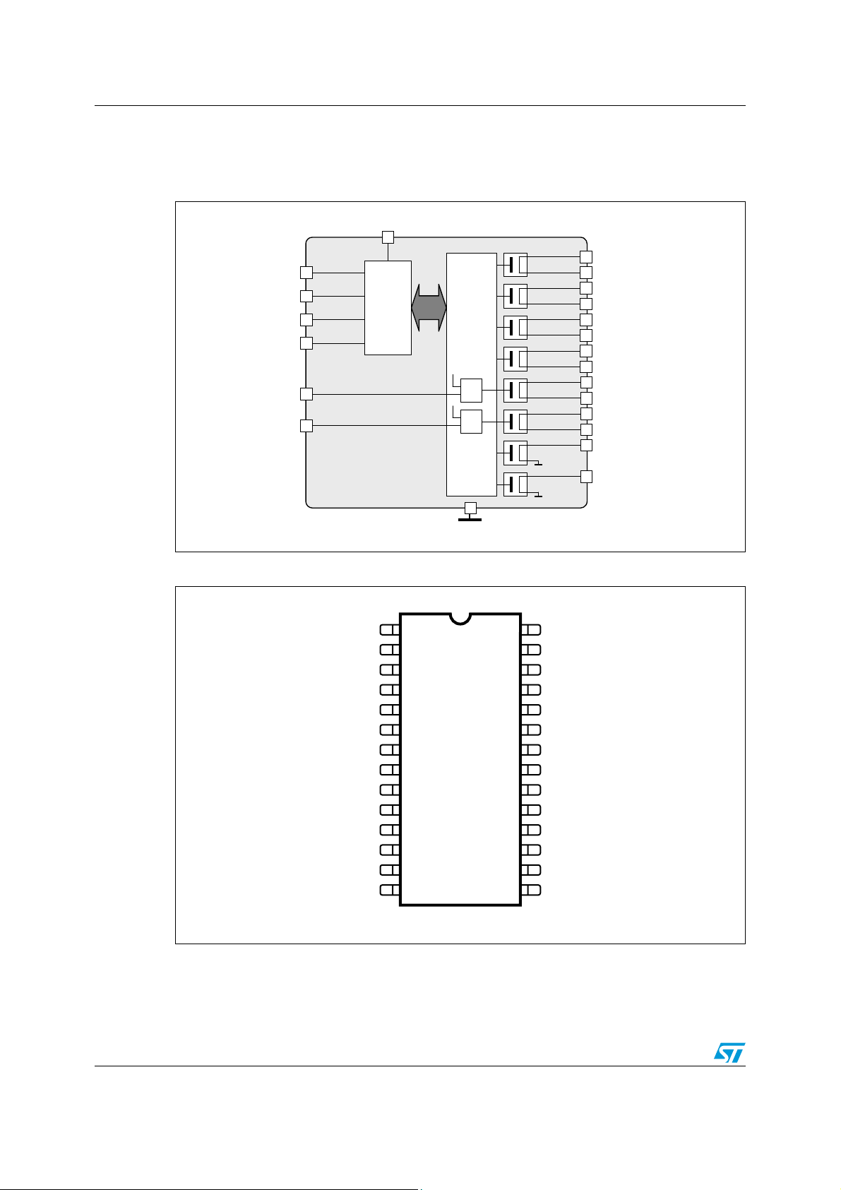
1 Block diagram and pin description
Figure 1. Block diagram
VDD=5V
SCLK
Di
DO
CS
PWM IN5
PWM IN6
Prepared by G. Bober, July 5 , 2001 System Competence Center Automotive Page 9
SPI
SO-28
Figure 2. Pin connection (top view)
Interface
Gate Driver
≥1
≥1
Automotive Business Unit Europe
GND
DRN1
SRC1
DRN2
SRC2
DRN3
SRC3
DRN4
SRC4
DRN5
SRC5
DRN6
SRC6
DRN7
DRN8
®
GND
VDD
DRN8
SRC2
DRN2
SRC1
DRN1
N.C.
IN6 IN5
SRC6 SRC5
2
3
4
5
6
7
8
9
10
DRN6
N.C.
N.C. CS
12
13
28
27
26
25
24
23
22
21
20
19
18
17
16
DO1
N.C.
DRN7
SCR4
DRN4
SRC3
DRN3
N.C.
DRN511
N.C.
1514SCLK DI
SO-28
6/27
Page 7
L9848 Block diagram and pin description
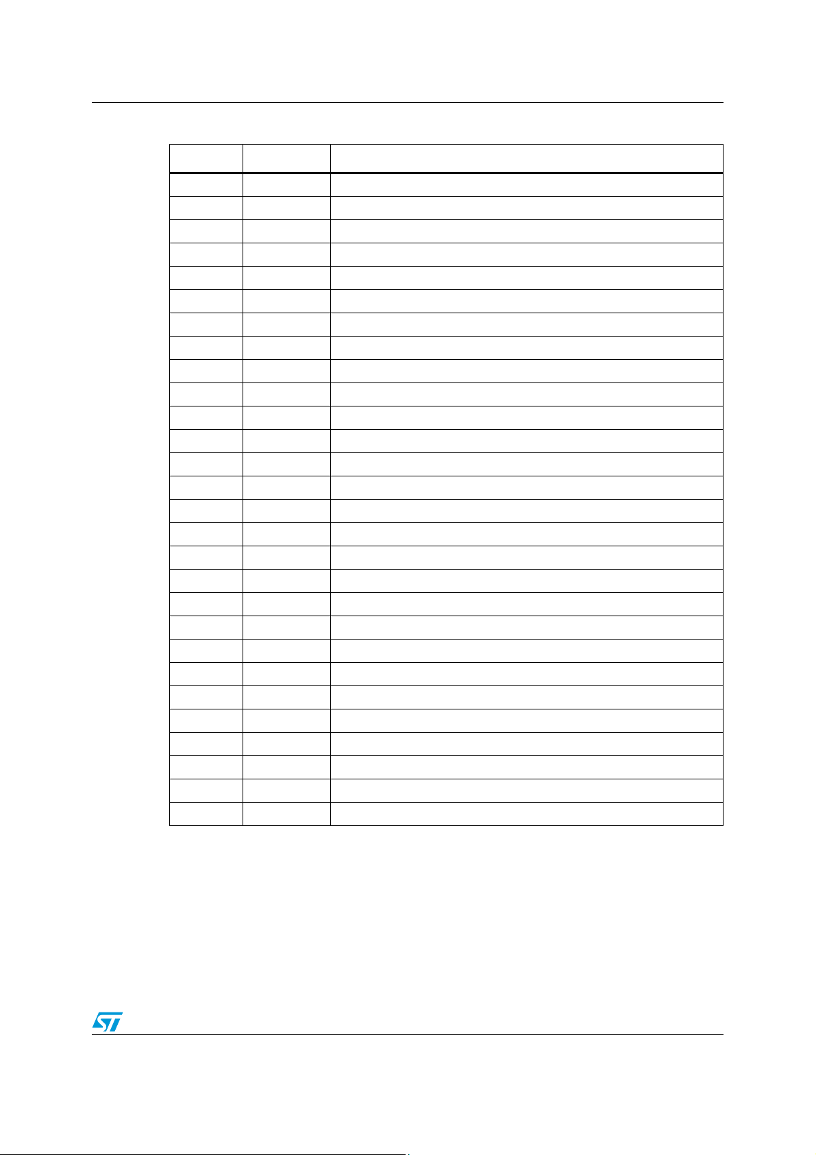
Table 2. Pin description
N° Pin Description
1 GND Analog ground
2 VDD 5V supply input
3 DRN8 Drain of low side driver #8
4 SRC2 Source of configurable driver #2
5 DRN2 Drain of configurable driver #2
6 SRC1 Source of configurable driver #1
7 DRN1 Drain of configurable driver #1
8 NC Not connected
9 IN6 PWM input for driver #6
10 SRC6 Source of configurable driver #6
11 DRN6 Drain of configurable driver #6
12 NC Not connected
13 NC Not connected
14 SCLK SPI serial clock input
15 DI SPI data in
16 CS SPI chip select (active high)
17 NC Not connected
18 DRN5 Drain of configurable driver #5
19 SRC5 Source of configurable driver #5
20 IN5 PWM input for driver #5
21 NC Not connected
22 DRN3 Drain of configurable driver #3
23 SRC3 Source of configurable driver #3
24 DRN4 Drain of configurable driver #4
25 SRC4 Source of configurable driver #4
26 DRN7 Drain of low side driver #7
27 NC Not connected
28 DO SPI data out
7/27
Page 8
Electrical specifications L9848
2 Electrical specifications
2.1 Absolute maximum ratings
Warning: For voltages and currents applied externally to the device.
This part may be irreparably damaged if taken outside the
specified absolute maximum rating range
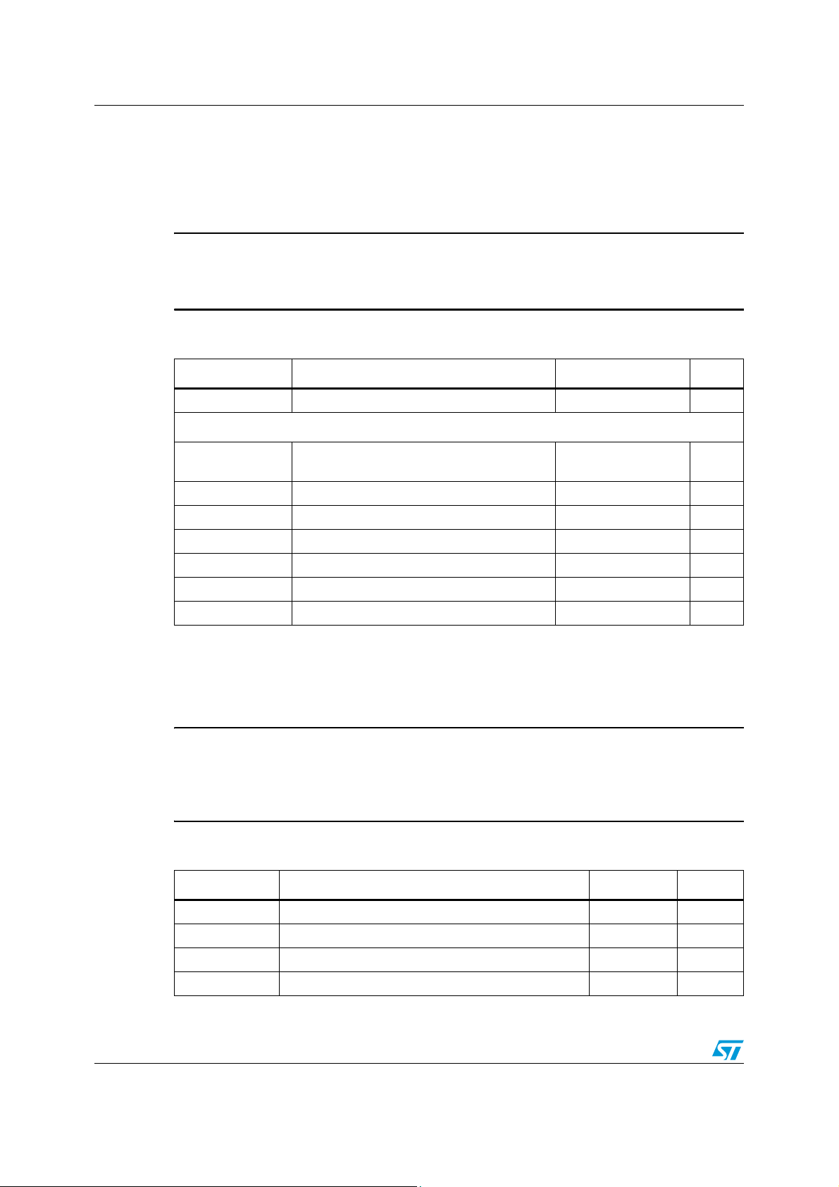
Table 3. Absolute maximum ratings
Symbol Parameter Value Unit
V
DD
Supply voltage -0.3 to 7.0 V
Pin voltages
VCS, VDI, VDO,
V
SCLK
V
, V
IN5
IN6
– V
V
SRC1
V
DRN1
V
SRC1
V
DRN1
1. Internally limited.
E
out 1-8
– V
– V
– V
SRC8
DRN6
SRC8
DRN6
Data lines voltages -0.3 to 7.0 V
Input voltages -0.3 to 7.0 V
Output DC voltages -13.5 to 40 V
Output DC voltages -13.5 to 60
Output transient voltages -20 to 40 V
Output transient voltages -20 to 60 V
Max. dissipation energy (@ 300mA) 60 mJ
2.2 Operation conditions
Warning: This part may not operate if taken outside the maximum
ratings. Once the condition is returned to within the specified
maximum rating or the power is re-cycled, the part will
recover with no damage or degradation.
(1)
V
Table 4. Operation conditions
Symbol Parameter Value Unit
V
DD
V
Batt
I
out
T
j
Supply voltage 4.75 to 5.25 V
Battery supply voltage 9 to 18 V
Output current (channel 1-8) 350 mA
Junction temperature -40 to 150 °C
8/27
Page 9
L9848 Electrical specifications
2.3 Thermal data
Table 5. Thermal data
Symbol Parameter Value Unit
T
st
R
th(j-a)
R
th(j-a)
1. With 6cm2 on board heatsink area.
Storage temperature -65 to 150 °C
Thermal resistance junction to ambient max. 70 °C/W
Thermal resistance junction to ambient
(1)
max. 50 °C/W
2.4 Electrical characteristcs
2.4.1 DC characteristics
CS(il)
DI(ih)
DI(il)
VDD
VDD
(T
= -40°C to 150°C, V
j
= 4.75 Vdc to 5.25 Vdc, V
DD
=9 V to 18 V, unless otherwise
Batt
specified)
IN5, 6 input voltage
IN5, 6 input current
CS input voltage
CS input current
SCLK input voltage
SCLK input current
DI input voltage
DI input current
V
IN5,6
V
IN5,6
V
CS
V
CS
V
SCLK
V
SCLK
V
DI
V
DI
= 0V
= V
= 0V
= V
= 0V
= V
dc
DD
= 0V
= V
dc
DD
dc
DD
dc
DD
0.8
30
0.8
30
0.8
0.8
VDD current All outputs ON 4.5 6 mA
VDD current All outputs OFF 0.5 2.0 5.0 mA
I
= 1.6 mA
DO output voltage
DO tri-state current
DO
= -200 µA VDD-0.8
I
DO
V
= 0V
DO
V
DO
= V
dc
DD
2.0 V
|10|
100
2.0 V
|10|
100
2.0 V
|10|
|10|
2.0 V
|10|
|10|
0.4
|10|
|10|
Table 6. Electrical characteristcs
Symbol Parameter Conditions Min. Typ. Max. Unit
V
IN5,6(ih)
V
IN5,6(il)
I
IN5,6(il)
I
IN5,6(ih)
V
CS(ih)
V
I
CS(il)
I
CS(ih)
V
SCLK(ih)
V
SCLK(il)
I
SCLK(il)
I
SCLK(ih)
V
V
I
DI((il)
I
DI((ih)
I
I
V
DO(ol)
V
DO(oh)
I
DO(zol)
I
DO(zoh)
V
µA
µA
V
µA
µA
V
µA
µA
V
µA
µA
V
V
µA
µA
9/27
Page 10

Electrical specifications L9848
Table 6. Electrical characteristcs (continued)
(T
= -40°C to 150°C, V
j
= 4.75 Vdc to 5.25 Vdc, V
DD
=9 V to 18 V, unless otherwise
Batt
specified)
Symbol Parameter Conditions Min. Typ. Max. Unit
I
DRN1-8(lk)
I
SRC1-6(lk)
I
DRN1-8(Sink)
I
SRC1-6(Sour)
I
DRN1-8(Limit)
I
SRC1-6(Limit)
V
DRN1-8(Cl+)
V
SRC1-6(Cl+)bat
V
SRC1-6GND
V
DRN1-8(Fault)
V
SRC1-6(Fault)
R
DSONDRN1-8
T
jTS
T
jTSH
POR
wih
DRN1-8 leakage
current (low side)
SRC1-6 leakage
current (high side)
DRN1-8 current sink
(low side)
SRC1-6 current
source (high side)
DRN1-8 current limit
(low side)
SRC1-6 current limit
(high side)
DRN1-8 clamp
voltage (low side)
SRC1-6 clamp
voltage (high side)
DRN1-8 fault voltage
(low side)
SRC1-6 fault voltage
(high side)
On-resistance
(DRN1-8)
Thermal shutdown
junction
temperature
(1)
Thermal shutdown
threshold hysteresis*
Power on reset
threshold on
=0.5Vdc, V
V
DD
V
DRN1-8
=18 V
VDD=0.5Vdc, V
=0.5Vdc, V
V
DD
DRN1-8
=18 V
V
VDD=0.5Vdc, V
V
V
V
V
V
V
V
V
V
V
V
V
V
V
V
T
=0Vdc, DI=00h,
SRC1-6
= 18 V
DRN1-8
=0Vdc, DI=00h,
SRC1-6
=0Vdc, DI=00h,
SRC1-6
=18 V
DRN1-8
=0Vdc, DI=00h,
SRC1-6
=0Vdc, DI=FFh,
SRC1-6
= 4-16 V
DRN1-8
=0-12 Vdc, DI=FFh,
SRC1-6
= V
DRN1-8
SRC1-6
DRN1-8
DRN
SRC1-6
DRN1-8=VBatt
=110 °C
j
Batt
=0Vdc, DI=00h, I
=25 V DI=00h, I
= 10 V; I
=0 Vdc, DI=00h 0.9V
Tj=25 °C
=-40 °C
T
j
=0Vdc,
SRC1-6
dc
SRC1-6
SRC1-6
dc
SRC1-6
dc
dc
=0V
dc, VDRN
=0Vdc,
=0V
dc, VDRN
V
DRN
V
DRN
=35 V
=35 V
=35 V
=35 V
-5
-10
50
50 60
-80
-100
0.1
1.5
-0.1
-1.5
-50
-60
10
80
100
-30
-30
0.8 1.3 1.8 A
dc
-0.8 1.3 -1.8 A
=10 mA 35 45 55 V
DRN1-8
V
DD
DD
Batt–
45
1.5
1.0
1.1V
0.65V
2.0
1.5
1.3
=10 mA
DRN1-8
= -10 mA -36 -31 -27 V
SRC
, DI=00h 0.55V
155 185 °C
515K
3.40 4.50 V
5
µA
µA
µA
µA
µA
µA
µA
µA
V
V
DD
D
D
V
W
W
W
POR
whyst
1. Guaranteed by design, not tested
Power on reset
hysteresis
10/27
0.4 0.8 V
Page 11

L9848 Electrical specifications
2.4.2 AC characteristics
Table 7. AC characteristics
(T
= - 40 °C to 150 °C, V
j
= 4.75 V to 5.25 Vdc, V
DD
= 9 V to 18 V, unless otherwise
Batt
specified)
Symbol Parameter Conditions Min. Typ. Max. Unit
t
DRN1-8slewon
t
DRN1-8slewoff
t
DRN1-8delon
t
DRN1-8deloff
t
DRN1-8deloffon
t
SRC1-6slewon
t
SRC1-6slewoff
t
SRC1-6delon
t
SRC1-6deloff
t
SRC1-6deloffon
C
DI
C
SCLK
t
DOrise
t
DOfall
t
DOacc
t
DOset
t
DOhold
t
DOdis
t
FltDlyInt
t
thFltDlyInt
Slew rate
(low side)
Tu r n o n
Tu r n o f f
Delay time
(low side)
Tu r n o n
Tu r n o f f
Delta
Slew rate
(high side)
Tu r n o n
Tu r n o f f
Delay time
(high side)
Tu r n o n
Turn Off
Delta
Input Capacitance*
Output data (DO)
Rise time
Fall time
Access time
Set up time
Hold time
Disable time
Fault delay time (Internal)
Thermal fault delay time
(Internal)
See Figure 4 and 5
See Figure 4 and 5
t
DRN1-8deloff
- t
DRN1-8delon
See Figure 4 and 5
See Figure 4 and 5
t
SRC1-6deloff
– t
SRC1-6delon
50 pF from DO to GND, see Fig. 6
50 pF from DO to GND, see Fig. 6
50 pF from DO to GND, see Fig. 7
50 pF from DO to GND, see Fig. 7
50 pF from DO to GND, see Fig. 7
No capacitor on DO, see Figure 3
Duration of open/short fault until
Fault Bit is ”Set”
Duration of thermal fault until
Fault Bit is ”Set”
10
10
2
10
20
10
10
2
10
20
25
25
10
50
50
25
50
100
100
20
100
60
100
100
20
100
60
20
20
30
30
70
20
10
140
100 300 µs
40 50 µs
µs
µs
µs
µs
µs
µs
µs
µs
µs
µs
pF
pF
ns
ns
ns
ns
ns
ns
11/27
Page 12

Electrical specifications L9848
Ω
Ω
f
f
Figure 3. DO loading for disable time measurement
V
1 k
DO
1 k
DD
+5 V
0 V
CS
4.0 V
t
DOdis
1.0 V
DO
Figure 4. Output loading for slew rate measurement
V
batt
High Side Configuration
600 Ω
DRN1-8
3 nF
Low Side Configuration
Figure 5. Output turn on/off delays and slew rates
IN1-8*
OUT1-8
t
DRN1-8slewon
t
DRN1-8delon
OUT1-6
t
SRC1-6slewof
t
SRC1-6deloff
* IN1-4, 7, 8 are available on wafer only.
90%
10% 10%
90%
10% 10%
SRC1-6
3 nF
IN1-8*
OUT1-8
t
DRN1-8slewof
t
DRN1-8deloff
OUT1-6
t
SRC1-6slewon
t
SRC1-6delon
600 Ω
90%
90%
12/27
Page 13

L9848 Electrical specifications
K
Figure 6. SPI input/output slew ratest
90%
10%
90% 90%
10%
t
CSrise
CS
Figure 7. SPI timing diagram
CS
t
CSlead
SCL
t
DOacc
DO
Fault MSB Bits 6 to 1 Fault LSB DI Data byte
10%
90%
t
SCLKlm
SCLKrise
t
CSfall
t
DOset
t
SCLKwid
t
DO
t
DOrise
t
DOhold
SCLK
10%
SCLKhm
t
DOfall
t
DIrise
t
t
SCLKfall
DI
t
DIfall
t
CSlag
t
DOdis
t
DIsus
t
DIhs
DI
MSB In
Bit 14 or 6
Bit 13 or 5
Bits 12 to 0
13/27
Page 14

Functional description L9848
3 Functional description
3.1 General features
The L9848 IC is a monolithic integrated circuit, which provides high flexibility for driving
medium loads. 8 outputs, whereof 6 (Output1-6) can be used as either internal low or high
side drives in any combination and 2 are dedicated low side outputs (Output7-8). The use of
this device reduces the I/O port requirements of the microprocessor by having serially
controlled outputs via a SPI interface. In addition, Output5-6 are capable of being PWMed
via an external pin (Input5-6). The 8bit SPI input is used to command the 8 output drivers
either ON or OFF and additional to indicate latched fault conditions that may have occurred.
Multiple L9848s may be daisy-chained with one additional microprocessor I/O port (CSn) for
each device. The implemented self-configuration allows the user to connect a high or low
side load to any of these outputs and the L9848 will drive them correctly as well as provide
proper fault mode operation with no other needed inputs. This device switch variable load
currents within the operation temperature range. The outputs are MOSFET drivers to
minimize Vdd current requirements. There's no V
the drains of high side outputs.
The L9848 meets all required specifications when the supply voltage applied to the drain(s)
of the outputs is within the operating range. For supply voltages applied to the drain(s) down
to 6.8V the part is functional however, it does not meet all parametric limits, i.e. output onstate voltages.
input pin however V
Batt
is connected to
Batt
3.2 Outputs - Common characteristics
The 6 self-configuring outputs (Outputs1-6) are able to drive either incandescent lamps,
inductive loads (non-PWMed), or resistive loads biased to VBatt. These outputs are enabled
and disabled via the SPI bus. Each of these outputs is short circuit current limited and has
an over-temperature protection as described under "Functional Description - Thermal
Shutdown".
When a high side configured output is commanded OFF after having been commanded ON,
the source voltage will go to the lesser negative of (VBatt-45V). This is due to the design of
the circuitry and the transconductance of the MOSFET.
When a low side configured output is commanded OFF after having been commanded ON,
the output voltage will rise to the internal zener clamp voltage (40 Vdc minimum) due to the
flyback of the inductive load.
3.2.1 Output 1-4
These four outputs can be used as either high or low side drives. Integrated current source
pull-ups and pull-downs are employed to correctly latch "open load" fault data. Both of these
current sources are needed to detect an open load state since these outputs self configure
as either high or low side drives.
Drain connections of output1-4 (DRN1-4)
These pins are connected to the drains of the n-channel MOSFET transistors.
Source connections of output1-4 (SRC1-4)
These pins are connected to the sources of the n-channel MOSFET transistors.
14/27
Page 15

L9848 Functional description
3.2.2 Output 5-6
These two self-configuring outputs can be used to drive either high or low side loads. In
addition to be controlled by the SPI BUS these outputs can also be enabled and disabled via
IN5 and IN6 inputs. IN5 and IN6 inputs are logically ORed with the SPI commands to allow
either the IN5-6 inputs or the SPI commands to activate these outputs. The use of IN5-6 for
PWM control on these outputs should only be done with non-inductive loads. Integrated
current source pull-ups and pull-downs are employed to correctly latch "open load" fault
data. Both of these current sources are needed to detect an open since these outputs self
configure as either high or low side drives.
Drain connections of Output5-6 (DRN5-6)
These pins are connected to the drains of the n-channel MOSFET transistors.
Source connections of Output5-6 (SRC5-6)
These pins are connected to the sources of the n-channel MOSFET transistors.
3.2.3 Output7-8
These two outputs (DRN7-8) are dedicated low side drives. Integrated current source pull
down are required to correctly latch "open load" fault data.
3.3 Main power input (VDD)
The VDD input is the primary power source of the L9848. This supply is used as the power
source for all of its logic circuitry and other miscellaneous functions. Notice that if the L9848
is interfaced to a processor operating with a lower voltage (e.g. 3.0 VDC), the
microprocessor inputs connected to the L9848 will swing from 0 to 5.0 VDC.
3.4 Discrete inputs (IN5-6)
These inputs allow Output5-6 to be enabled via this external pin without the use of the SPI.
A logic "1" on these inputs enables the corresponding output no matter what the status of
the SPI command register. A logic "0" on these inputs disables the corresponding output if
the SPI command register is not commanding this output on. These pins can be left "open"
if the outputs are controlled only via the SPI (internally pulled down). These inputs are
ideally suited for non-inductive loads that are pulse width modulated (PWMed). This allows
PWM control without the use of the SPI. The TTL level compatible input voltages allow
proper operation with microprocessors that are using 5.0V or 3.0V for their Vdd supply.
3.5 Serial peripheral interface (SPI)
A standard serial peripheral interface, consisting of Serial Clock (SCLK), Data Out (DO),
Data In (DI), and Chip Select (CS) is implemented to allow access to the internal registers of
the L9848. All outputs are controlled via the SPI.The input pins CS, SCLK, and DI have TTL
level compatible input voltages allowing proper operation from microprocessors that are
using 5.0V or 3.0V for their VDD supply. The design of the L9848 allows a "daisy-chaining"
of multiple L9848's to further reduce the need for controller pins.
15/27
Page 16

Functional description L9848
3.5.1 Serial data output (DO)
This output pin is in a tri-state condition when CS is a logic "0" (LOW). When CS is a logic
"1" (HIGH), this pin always transmits 8bits of data from the fault register to the digital
controller. After the first 8bits data are transmitted the DO output then sequentially transmits
the digital data that was just received (8 SCLK cycles earlier) on the DI pin. The DO output
continues to transmit the 8 SCLK delayed bit data from the DI input until CS eventually
transitions from a logic "1" to a logic "0". DO data changes state 10 ns or later, after the
falling edge of SCLK. By definition, the MSB (Table 3) is the first bit of the byte transmitted
on DO and the LSB is the last bit of the byte transmitted on DO, once CS transitions from a
logic "0" to a logic "1".
3.5.2 Serial data input (DI)
This input takes data from the digital controller while CS is HIGH. The L9848 accepts an 8bit
data stream to command the outputs ON or OFF. By definition, the MSB (Table 1) is the first
bit of each byte received on DI and the LSB is the last bit of each byte received on DI, once
CS transitions from a logic "0" to a logic "1".
3.5.3 Chip select (CS)
This is the chip select input pin. On the rising edge of CS, the DO pin switches from tri-state
to active-out mode. While CS is high, register data is shifted in and shifted out by the DI and
DO pin, respectively, on each subsequent SCLK. On the falling edge of CS, the DO pin
switches back to tri-state mode and the fault register will be "Cleared" if a valid DI byte was
received.
A valid DI byte is defined as such:
st
1
A multiple of 8 bits was received
nd
2
SCLK was low when CS went low
rd
3
Current SPI cycle started when SCLK was low
The fault data is not cleared unless all of the 3 previous conditions have been met. A SCLK
transition must be seen before CS is interpreted as active. To allow sufficient time to reload
the fault registers, the CS pin must remain low for a minimum of 1µs prior to going high
again, before it starts shifting the fault data bits out on the DO pin. CS has an integrated
glitch filter for spurious pulses of 50ns or shorter (i.e. no fault data and Outputs1-8 enable
status will be altered). For open circuit condition the CS is internally pulled down to GND.
3.5.4 Serial clock (SCLK)
This is the clock signal input for synchronization of serial data transfer. DI data is shifted into
the DI input on the rising edge of SCLK and DO data changes on the falling edge of SCLK.
16/27
Page 17

L9848 Functional description
3.6 SPI DI input command register
An input byte (8 bits) is routed to the Command Register. The content of this Command
Register is given in Ta bl e 8 and Tab le 9 . Additional DI data will continue to be wrapped
around to the DO pin. If CS will go low before a complete reception of the current byte, this
just transmitted byte will be ignored
Table 8. Bit command register definition
MSB LSB
OUT8 OUT7 OUT6 OUT5 OUT4 OUT3 OUT2 OUT1
D07D06D05D04D03D02D01D00
Table 9. Command register logic definition
Bit State Status
D00-D07 0 OUTPUT1-8 are commanded OFF
D00-D07 1 OUTPUT1-8 are commanded ON
3.7 Fault operation
The fault diagnostic capability consists of one internal 8bit shift register. Open or shorted
load detection is provided by comparing the source or drain voltage with the VDD voltage.
When an output connected as either a low side device or a high side device is commanded
OFF, an open load can be detected. When an output connected as either a low side device
or a high side device is commanded ON a shorted load can be detected.
The fault bit is "set" for each channel if a short, open, or over-temperature condition occurs
for Outputs1-8. The content of this Fault Register is given in Ta bl e 1 0 .
The output load status of each individual channel is defined in Ta bl e 1 1 . Open and shorts
are subsequently re-latched provided they meet the minimum duration criterion and thermal
faults will be re-latched provided they meet the duration criterion after CS goes "LOW", if
these fault conditions are still present.
The fault register is capable of detecting and latching multiple fault conditions (among the 8
outputs) that have occurred between clearing of the fault flags.
All of the faults will be cleared on the falling edge of Chip Select (CS).
Table 10. Fault register definition
MSB LSB
Fault8 Fault7 Fault6 Fault5 Fault4 Fault3 Fault2 Fault1
D07 D06 D05 D04 D03 D02 D01 D00
Table 11. Fault logic definition
BIT STATE STATUS
Fault1-8 0 OUT1-8 are not open or shorted (nominal)
Fault1-8 1 OUT1-8 are either open or shorted or in thermal shutdown
17/27
Page 18

Functional description L9848
3.7.1 Initial fault register SPI Cycle
After initial application of VDD to the L9848, the fault register is "Cleared" by the POR
circuitry during the initial SPI cycle, and all subsequent cycles, valid fault data will be clocked
out of DO (fault bits). The bits that are "Set" indicate which particular output(s) have a fault
condition.
3.7.2 Incandescent lamp outputs
Software filtering may be needed to ignore fault signals due to the long turn on delay
associated with lamp loads. For example, the lamp load channel gets enabled during one
SPI cycle. Approximately 20ms-100ms later, a SPI cycle is required to read the correct fault
latch data, which will be cleared after the falling edge of CS of that SPI cycle.
3.8 Configuration for Output1-6
The drain and source pins for each output must be connected in one of the two following
configurations (see Figure 6a and Figure 6b).
3.8.1 Low side drivers
When any combination of Output1-6 are connected in a low side drive configuration the
source of the applicable output (SRC1-6) has to be connected to ground. The drain of the
applicable output (DRN1-6) has to be connected to the low side of the load.
3.8.2 High side drivers
When any combination of Output1-6 are connected in a high side drive configuration the
drain of the applicable output (DRN1-6) has to be connected to VBatt. The source of the
applicable output (SRC1-6) has to be connected to the high side of the load.
3.9 DRN1-6 susceptibility to negative voltage transients
For any output(s) connected and used for a high side drive a fast negative transient slew
rate does not inadvertently issue a POR (power on reset) or cause parasitic latching to
occur. Nevertheless under some conditions it may be necessary to have a ceramic chip
capacitor of 10nF to 100nF connected from drain to GND to aid in preventing the occurance
of a problem due to very fast negative transient(s) on the drain(s) of the device.
18/27
Page 19

L9848 Functional description
3.10 Thermal shutdown
Each of the 8 outputs have independent thermal protection circuitry that disables each
output driver once the local n-channel MOSFET device temperature reaches the
overtemperature shutdown limit. Due to the hysteresis of the enable and disable
temperature levels the faulted channel will periodically turn off and on until the fault condition
is cleared, the ambient temperature is decreased sufficiently or the output is commanded
OFF.
Once any individual channel goes into thermal shutdown, a logic "1" is latched into the Fault
Register if it meets the thermal fault filter (Note: does NOT go through the open/short fault
filter).
Note: Due to the design of the L9848 each output's thermal limit "may not" be truly independent to
the extent that if one output is shorted, it may impact the operation of other outputs (due to
lateral heating in the die). The user may be required to monitor the fault bits periodically. If a
fault bit is "Set" for the last enabled output, and subsequently, fault bits for other enabled
outputs start to be "Set", the user will send two SPI write cycles within 100ms of each other.
The first SPI write cycle will "Clear" the fault latches. If multiple faults are indicated after the
second SPI write cycle, these faults are most likely thermal faults. The user will then disable
this output that was most recently enabled. The fault register should be subsequently
interrogated to verify proper operations of the other enabled output channels.
3.11 Charge pump usage
The L9848 uses a separate charge pump and oscillator for each of the 6 configurable output
channels to provide low RDSON values when connected in a high side configuration These
oscillators are operating in a non-synchronous mode of operation. The frequency range of
these charge pumps is designed to be above the AM radio band and below 8.0 MHz so that
harmonics do not get within the FM radio band.
3.12 Waveshaping
Both the turn on and the turn off slew rates on all outputs (OUTPUT1-8) are limited to
reduce conducted EMC energy in the vehicle's wiring harness.
The characteristic of the turn-on and turn-off voltage is linear, with no discontinuities, during
the output driver state transition.
3.13 POR register initialization
L9848 wakes up if the VDD supply increases from 0 to 5VDC in 0.3ms to 3ms.
The L9848 has a POR circuit, which monitors the VDD voltage. When the VDD voltage
reaches roughly 4.1VDC, and remains above this trip level for minimum 20µs, the Command
and Fault Registers are "cleared". Before VDD reaches this trip level, all eight outputs are
guaranteed in OFF-state.
After a valid POR has occurred and the VDD voltage falls below the valid high level for a
required amount of time, the L9848 is powered down in a fully controlled manner. No
outputs will glitch "ON" and no erroneous fault data is allowed on the DO output.
19/27
Page 20

Functional description L9848
3.14 Abnormal voltage conditions
The L9848 survives the following abnormal voltage conditions.
3.14.1 Reverse Battery
applied either directly, or through a load to the drain pins (DRN1-6) with the source pins
(SRC1-6) connected to a load or to ground (cold lamp, solenoid, etc).
3.14.2 Maximum negative transients
that force the drains or sources of the outputs going -20V below the module ground.
3.14.3 Ground offsets
with a maximum of -0.5V to 1.0V between the L9848 ground and any load directly
connected to a chassis ground in the case of high side loads. If driving a low side load there
will not be an offset between the L9848 ground and the load ground. In addition there may
be a maximum ground difference between the L9848 ground and any other module
interfacing with it of -0.5V to 1.0V or ±VAC (10-200Hz).
3.14.4 Loss of ground operation
Any outputs are protected to become active in case of lost ground of the L9848 module with
the supply is still applied.
20/27
Page 21

L9848 Functional block diagram
4 Functional block diagram
Figure 8. L9848 with external components
DRN1
7
SRC1
6
or
DRN1
7
SRC1
6
DRN2
5
SRC2
4
or
DRN2
5
SRC2
4
DRN3
+5V
DC
C2
0.01μF
V
DD
2
22
SRC3
23
or
DRN3
22
SRC3
23
FROM CPU
TO CPU
(FAN OUT CAP
50nF)
IN5
IN6
CS
SCLK
DO
GND
20
9
DI
15
16
14
28
1
DRN4
24
SRC4
25
or
DRN4
24
SRC4
25
DRN7
26
DRN8
3
DRN5
18
100nF
SRC5
19
or
DRN5
18
SRC5
19
DRN6
11
SRC6
10
or
DRN6
11
SRC6
10
100nF
100nF
100nF
D02AT511A
V
BATT
21/27
Page 22

Application examples L9848
5 Application examples
Figure 9. L9848 as mirror axis control motor drivers
Vbatt
M
Simultaneous motor drive
for seat adjustment memory
M
SCK
SDI
SDO
CS
PWM
IN5
PWM
IN6
Vdd 5V
SPI
+ Data
Interface
Gate
Driver
Inter-
face
GND
Figure 10. L9848 as mirror motor and bulb driver
Vbatt
SCK
SDI
SDO
CS
PWM
IN5
PWM
IN6
Vdd 5V
SPI
+ Data
Interface
Gate
Driver
Inter-
face
LED Chain
Side Turn Indicator
5W
Safety Light
M
Sequential motor drive
M
GND
22/27
Page 23

L9848 Application examples
Figure 11. L9848 as window lift relay and mirror motor driver
Vbatt
M
Vbatt
SCK
SDI
SDO
CS
Vdd 5V
SPI
+ Data
Interface
Gate
Driver
Inter-
face
PWM
IN5
PWM
IN6
GND
Figure 12. L9848 as bipolar stepper motor driver
Vdd 5V
SCK
SDI
SDO
CS
SPI
+ Data
Interface
Gate
Driver
Inter -
face
M
M
Power windo w
Vbatt
PWM
IN5
PWM
IN6
SM
GND
23/27
Page 24

Application examples L9848
Figure 13. L9848 driving approach for 3 bipolar stepper-motors in sequential mode
for climate applications as window lift relay and mirror motor driver
Stepper-Motor 1 active
SPI
L9848
L9848
disabled
disabled
disabled
disabled
SM
SM
SM
1
2
3
24/27
Page 25

L9848 Package information
6 Package information
In order to meet environmental requirements, ST (also) offers these devices in ECOPACK®
packages. ECOPACK
®
packages are lead-free. The category of second Level Interconnect
is marked on the package and on the inner box label, in compliance with JEDEC Standard
JESD97. The maximum ratings related to soldering conditions are also marked on the inner
box label.
ECOPACK is an ST trademark. ECOPACK specifications are available at: www.st.com.
Figure 14. SO-28 mechanical data and package dimensions
DIM.
A 2.65 0.104
a1 0.1 0.3 0.004 0.012
b 0.35 0.49 0.014 0.019
b1 0.23 0.32 0.009 0.013
C 0.5 0.020
c1 45° (typ.)
D 17.7 18.1 0.697 0.713
E 10 10.65 0.394 0.419
e 1.27 0.050
e3 16.51 0.65
F 7.4 7.6 0.291 0.299
L 0.4 1.27 0.016 0.050
S8
mm inch
MIN. TYP. MAX. MIN. TYP. MAX.
(max.)
°
OUTLINE AND
MECHANICAL DATA
SO-28
25/27
Page 26

Revision history L9848
7 Revision history
Table 12. Document revision history
Date Revision Changes
12-Jul-2003 4 Initial release.
Document reformatted.
18-Nov-2008 5
Updated Table 2: Pin description.
Updated Figure 8: L9848 with external components.
Updated Section 6: Package information on page 25.
26/27
Page 27

L9848
Please Read Carefully:
Information in this document is provided solely in connection with ST products. STMicroelectronics NV and its subsidiaries (“ST”) reserve the
right to make changes, corrections, modifications or improvements, to this document, and the products and services described herein at any
time, without notice.
All ST products are sold pursuant to ST’s terms and conditions of sale.
Purchasers are solely responsible for the choice, selection and use of the ST products and services described herein, and ST assumes no
liability whatsoever relating to the choice, selection or use of the ST products and services described herein.
No license, express or implied, by estoppel or otherwise, to any intellectual property rights is granted under this document. If any part of this
document refers to any third party products or services it shall not be deemed a license grant by ST for the use of such third party products
or services, or any intellectual property contained therein or considered as a warranty covering the use in any manner whatsoever of such
third party products or services or any intellectual property contained therein.
UNLESS OTHERWISE SET FORTH IN ST’S TERMS AND CONDITIONS OF SALE ST DISCLAIMS ANY EXPRESS OR IMPLIED
WARRANTY WITH RESPECT TO THE USE AND/OR SALE OF ST PRODUCTS INCLUDING WITHOUT LIMITATION IMPLIED
WARRANTIES OF MERCHANTABILITY, FITNESS FOR A PARTICULAR PURPOSE (AND THEIR EQUIVALENTS UNDER THE LAWS
OF ANY JURISDICTION), OR INFRINGEMENT OF ANY PATENT, COPYRIGHT OR OTHER INTELLECTUAL PROPERTY RIGHT.
UNLESS EXPRESSLY APPROVED IN WRITING BY AN AUTHORIZED ST REPRESENTATIVE, ST PRODUCTS ARE NOT
RECOMMENDED, AUTHORIZED OR WARRANTED FOR USE IN MILITARY, AIR CRAFT, SPACE, LIFE SAVING, OR LIFE SUSTAINING
APPLICATIONS, NOR IN PRODUCTS OR SYSTEMS WHERE FAILURE OR MALFUNCTION MAY RESULT IN PERSONAL INJURY,
DEATH, OR SEVERE PROPERTY OR ENVIRONMENTAL DAMAGE. ST PRODUCTS WHICH ARE NOT SPECIFIED AS "AUTOMOTIVE
GRADE" MAY ONLY BE USED IN AUTOMOTIVE APPLICATIONS AT USER’S OWN RISK.
Resale of ST products with provisions different from the statements and/or technical features set forth in this document shall immediately void
any warranty granted by ST for the ST product or service described herein and shall not create or extend in any manner whatsoever, any
liability of ST.
ST and the ST logo are trademarks or registered trademarks of ST in various countries.
Information in this document supersedes and replaces all information previously supplied.
The ST logo is a registered trademark of STMicroelectronics. All other names are the property of their respective owners.
© 2008 STMicroelectronics - All rights reserved
STMicroelectronics group of companies
Australia - Belgium - Brazil - Canada - China - Czech Republic - Finland - France - Germany - Hong Kong - India - Israel - Italy - Japan -
Malaysia - Malta - Morocco - Singapore - Spain - Sweden - Switzerland - United Kingdom - United States of America
www.st.com
27/27
 Loading...