

Features
■ For air and liquid cooled applications
■ DF output (inverted field monitor)
■ Thermal protection
■ FIeld driver, lamp driver, relay driver, and DF
(field monitor) short circuit protected
■ Load response control
■ Single phase autostart
Description
The L9466 is a monolithic multifunction generator
Voltage regulator intended for use in automotive
charging applications.
Table 1. Device summary
L9466
Car alternator voltage regulator
Multiwatt8
This All Silicon Voltage Regulator regulates the
output of an automotive generator by controlling
the field winding current by means of a variable
frequency PWM high side driver.
Order code Package Packing
L9466N Multiwatt8 Tube
October 2008 Rev 2 1/11
www.st.com
11

Contents L9466
Contents
1 Block diagram . . . . . . . . . . . . . . . . . . . . . . . . . . . . . . . . . . . . . . . . . . . . . . 3
2 Pin description . . . . . . . . . . . . . . . . . . . . . . . . . . . . . . . . . . . . . . . . . . . . . 4
3 Electrical specifications . . . . . . . . . . . . . . . . . . . . . . . . . . . . . . . . . . . . . . 5
3.1 Absolute maximum ratings . . . . . . . . . . . . . . . . . . . . . . . . . . . . . . . . . . . . . 5
3.2 Thermal data . . . . . . . . . . . . . . . . . . . . . . . . . . . . . . . . . . . . . . . . . . . . . . . 5
3.3 Electrical characteristics . . . . . . . . . . . . . . . . . . . . . . . . . . . . . . . . . . . . . . . 5
4 Package information . . . . . . . . . . . . . . . . . . . . . . . . . . . . . . . . . . . . . . . . . 9
5 Revision history . . . . . . . . . . . . . . . . . . . . . . . . . . . . . . . . . . . . . . . . . . . 10
2/11
L9466 Block diagram
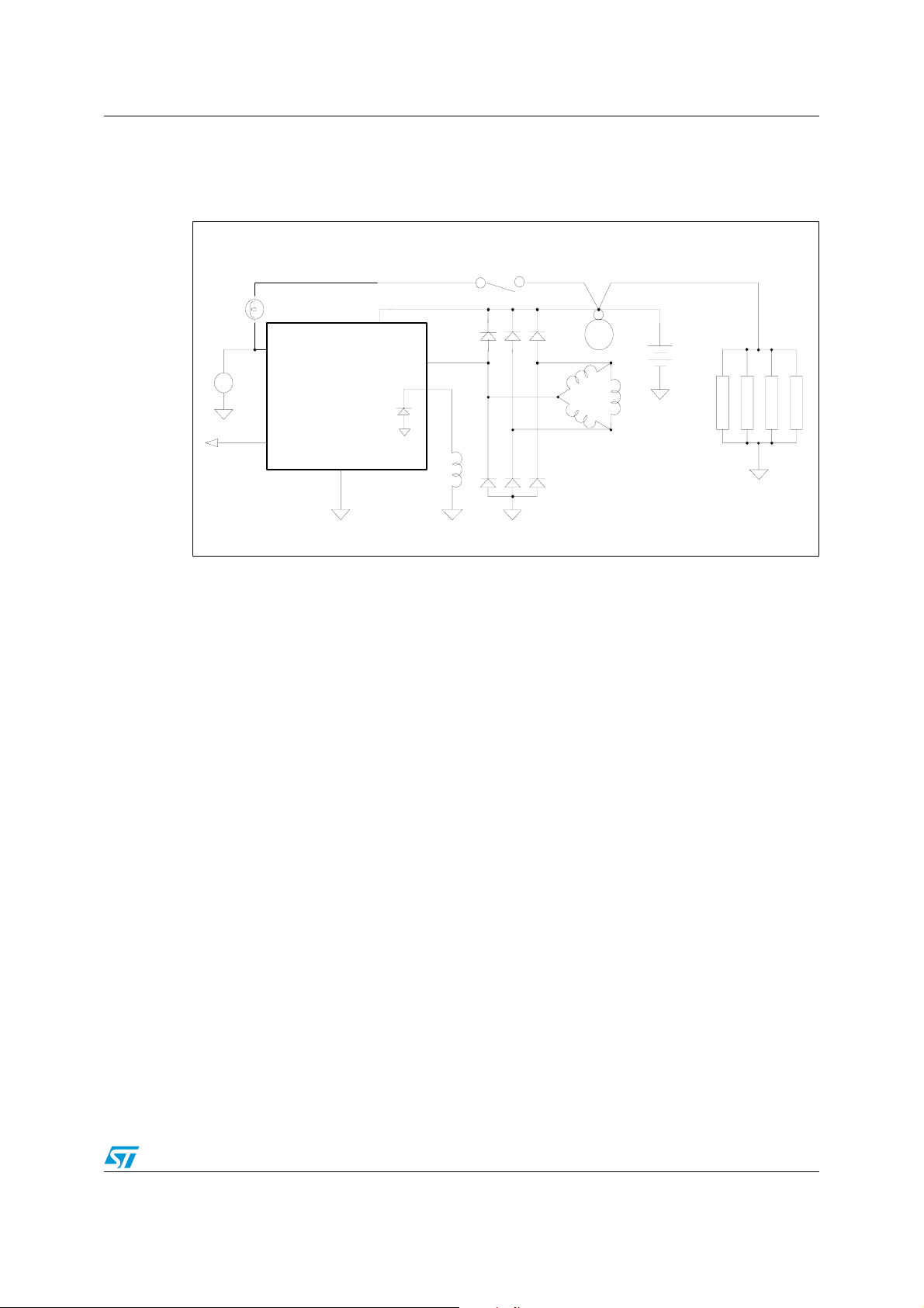
1 Block diagram
Figure 1. Block diagram
Key SW.
Fault
R
Relay
Lamp
L
ASVR
VGO
P
F+
Starter
Battery
Stator
To
ECM
DF
C
Field
(Rotor)
Rectifier
Bridge
Loads
3/11
Pin description L9466
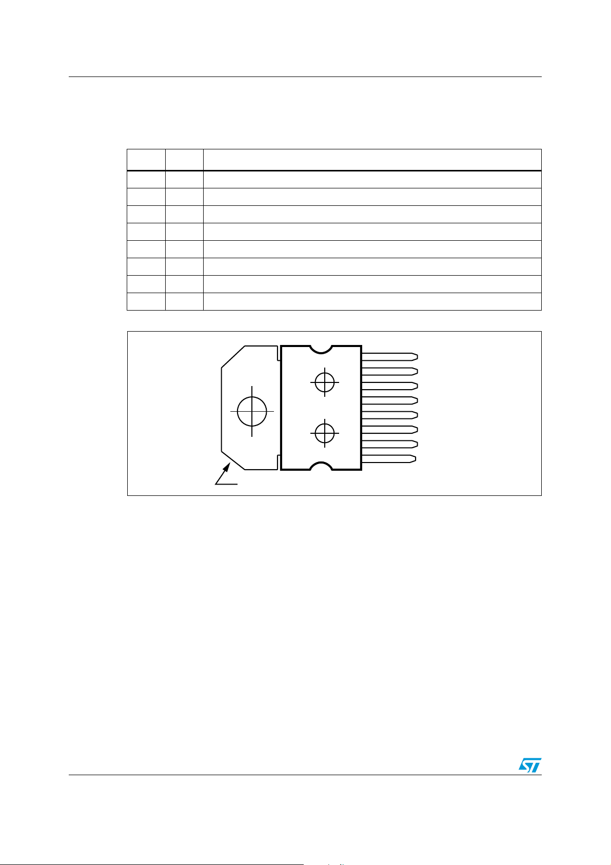
2 Pin description
Table 2. Pin description
N° Pin Description
1V
Generator Output – Voltage Sense and Power Supply to ASVR
GO
2 F+ Field Driver - High Side Drive Output
3 G Ground for ASVR (Must be connected for Ground for ASVR)
4 NC Not connected
5 Gnd Internally connected to the Tab or Slug in MW-8.
6 DF Inverted Field Monitor Output
7 L Lamp - Low Side Driver; Relay - High Side Driver
8 P Phase Sense Input
Figure 2. Pin connection (top view)
8
7
6
5
4
3
2
1
P
L
DF
GND
NC
G
F+
V
GO
Tab connected to pin 5
4/11
D02AT502B
 Loading...