

dSPIN fully integrated microstepping motor driver
Features
■ Operating voltage: 8 - 45 V
■ 7.0 A output peak current (3.0 A r.m.s.)
■ Low R
■ Programmable speed profile
■ Programmable Power MOSFET slew rate
■ Up to 1/16 microstepping
■ Predictive current control with adaptive decay
■ Non-dissipative current sensing
■ SPI interface
■ Low quiescent and standby currents
■ Programmable non-dissipative overcurrent
protection on all Power MOSFETs
■ Two levels of overtemperature protection
Applications
■ Bipolar stepper motor
power MOSFETs
DSon
L6472
with motion engine and SPI
POWERSO36
All application commands and data registers,
including those used to set analog values (i.e.
current control value, current protection trip point,
dead time, etc.) are sent through a standard 5Mbit/s SPI.
A very rich set of protections (thermal, low bus
voltage, overcurrent) makes the L6472 “bullet
proof”, as required by the most demanding motor
control applications.
Table 1. Device summary
Order codes Package Packing
HTSSOP28
Description
L6472H HTSSOP28 Tube
L6472HTR HTSSOP28 Tape and reel
The L6472, realized in analog mixed signal
technology, is an advanced fully integrated
solution suitable for driving two-phase bipolar
stepper motors with microstepping. It integrates a
dual low R
DMOS full bridge with all of the
DS(on)
power switches equipped with an accurate onchip current sensing circuitry suitable for nondissipative current control and overcurrent
protection. Thanks to a new current control, a
1/16 microstepping is achieved through an
adaptive decay mode which outperforms
traditional implementations. The digital control
core can generate user defined motion profiles
with acceleration, deceleration, speed or target
position, easily programmed through a dedicated
register set.
January 2012 Doc ID 022729 Rev 1 1/69
L6472PD POWERSO36 Tube
L6472PDTR POWERSO36 Tape and reel
www.st.com
69

Contents L6472
Contents
1 Block diagram . . . . . . . . . . . . . . . . . . . . . . . . . . . . . . . . . . . . . . . . . . . . . . 6
2 Electrical data . . . . . . . . . . . . . . . . . . . . . . . . . . . . . . . . . . . . . . . . . . . . . . 7
2.1 Absolute maximum ratings . . . . . . . . . . . . . . . . . . . . . . . . . . . . . . . . . . . . . 7
2.2 Recommended operating conditions . . . . . . . . . . . . . . . . . . . . . . . . . . . . . 8
2.3 Thermal data . . . . . . . . . . . . . . . . . . . . . . . . . . . . . . . . . . . . . . . . . . . . . . . 8
3 Electrical characteristics . . . . . . . . . . . . . . . . . . . . . . . . . . . . . . . . . . . . . 9
4 Pin connection . . . . . . . . . . . . . . . . . . . . . . . . . . . . . . . . . . . . . . . . . . . . . 14
4.1 Pin list . . . . . . . . . . . . . . . . . . . . . . . . . . . . . . . . . . . . . . . . . . . . . . . . . . . . 15
5 Typical applications . . . . . . . . . . . . . . . . . . . . . . . . . . . . . . . . . . . . . . . . 17
6 Functional description . . . . . . . . . . . . . . . . . . . . . . . . . . . . . . . . . . . . . . 18
6.1 Device power-up . . . . . . . . . . . . . . . . . . . . . . . . . . . . . . . . . . . . . . . . . . . . 18
6.2 Logic I/O . . . . . . . . . . . . . . . . . . . . . . . . . . . . . . . . . . . . . . . . . . . . . . . . . . 18
6.3 Charge pump . . . . . . . . . . . . . . . . . . . . . . . . . . . . . . . . . . . . . . . . . . . . . . 18
6.4 Microstepping . . . . . . . . . . . . . . . . . . . . . . . . . . . . . . . . . . . . . . . . . . . . . . 19
6.4.1 Automatic full-step mode . . . . . . . . . . . . . . . . . . . . . . . . . . . . . . . . . . . . 20
6.5 Absolute position counter . . . . . . . . . . . . . . . . . . . . . . . . . . . . . . . . . . . . . 20
6.6 Programmable speed profiles . . . . . . . . . . . . . . . . . . . . . . . . . . . . . . . . . 20
6.6.1 Infinite acceleration/deceleration mode . . . . . . . . . . . . . . . . . . . . . . . . . 21
6.7 Motor control commands . . . . . . . . . . . . . . . . . . . . . . . . . . . . . . . . . . . . . 21
6.7.1 Constant speed commands . . . . . . . . . . . . . . . . . . . . . . . . . . . . . . . . . . 21
6.7.2 Positioning commands . . . . . . . . . . . . . . . . . . . . . . . . . . . . . . . . . . . . . . 22
6.7.3 Motion commands . . . . . . . . . . . . . . . . . . . . . . . . . . . . . . . . . . . . . . . . . 23
6.7.4 Stop commands . . . . . . . . . . . . . . . . . . . . . . . . . . . . . . . . . . . . . . . . . . . 23
6.7.5 Step-clock mode . . . . . . . . . . . . . . . . . . . . . . . . . . . . . . . . . . . . . . . . . . 23
6.7.6 GoUntil and ReleaseSW commands . . . . . . . . . . . . . . . . . . . . . . . . . . . 24
6.8 Internal oscillator and oscillator driver . . . . . . . . . . . . . . . . . . . . . . . . . . . 25
6.8.1 Internal oscillator . . . . . . . . . . . . . . . . . . . . . . . . . . . . . . . . . . . . . . . . . . 25
6.8.2 External clock source . . . . . . . . . . . . . . . . . . . . . . . . . . . . . . . . . . . . . . . 25
2/69 Doc ID 022729 Rev 1

L6472 Contents
6.9 Overcurrent detection . . . . . . . . . . . . . . . . . . . . . . . . . . . . . . . . . . . . . . . . 26
6.10 Undervoltage lockout (UVLO) . . . . . . . . . . . . . . . . . . . . . . . . . . . . . . . . . 27
6.11 Thermal warning and thermal shutdown . . . . . . . . . . . . . . . . . . . . . . . . . 27
6.12 Reset and standby . . . . . . . . . . . . . . . . . . . . . . . . . . . . . . . . . . . . . . . . . . 27
6.13 External switch (SW pin) . . . . . . . . . . . . . . . . . . . . . . . . . . . . . . . . . . . . . 28
6.14 Programmable DMOS slew rate, dead time and blanking time . . . . . . . . 28
6.15 Integrated analog-to-digital converter . . . . . . . . . . . . . . . . . . . . . . . . . . . . 28
6.16 Internal voltage regulator . . . . . . . . . . . . . . . . . . . . . . . . . . . . . . . . . . . . . 29
6.17 BUSY\SYNC pin . . . . . . . . . . . . . . . . . . . . . . . . . . . . . . . . . . . . . . . . . . . . 29
6.17.1 BUSY operation mode . . . . . . . . . . . . . . . . . . . . . . . . . . . . . . . . . . . . . . 29
6.17.2 SYNC operation mode . . . . . . . . . . . . . . . . . . . . . . . . . . . . . . . . . . . . . . 30
6.18 FLAG pin . . . . . . . . . . . . . . . . . . . . . . . . . . . . . . . . . . . . . . . . . . . . . . . . . 30
7 Phase current control . . . . . . . . . . . . . . . . . . . . . . . . . . . . . . . . . . . . . . . 31
7.1 Predictive current control . . . . . . . . . . . . . . . . . . . . . . . . . . . . . . . . . . . . . 31
7.2 Auto-adjusted decay mode . . . . . . . . . . . . . . . . . . . . . . . . . . . . . . . . . . . . 33
7.3 Auto-adjusted fast decay during the falling steps . . . . . . . . . . . . . . . . . . . 34
7.4 Torque regulation (output current amplitude regulation) . . . . . . . . . . . . . . 35
8 Serial interface . . . . . . . . . . . . . . . . . . . . . . . . . . . . . . . . . . . . . . . . . . . . . 36
9 Programming manual . . . . . . . . . . . . . . . . . . . . . . . . . . . . . . . . . . . . . . . 38
9.1 Register and flag description . . . . . . . . . . . . . . . . . . . . . . . . . . . . . . . . . . 38
9.1.1 ABS_POS . . . . . . . . . . . . . . . . . . . . . . . . . . . . . . . . . . . . . . . . . . . . . . . 39
9.1.2 EL_POS . . . . . . . . . . . . . . . . . . . . . . . . . . . . . . . . . . . . . . . . . . . . . . . . . 39
9.1.3 MARK . . . . . . . . . . . . . . . . . . . . . . . . . . . . . . . . . . . . . . . . . . . . . . . . . . 40
9.1.4 SPEED . . . . . . . . . . . . . . . . . . . . . . . . . . . . . . . . . . . . . . . . . . . . . . . . . . 40
9.1.5 ACC . . . . . . . . . . . . . . . . . . . . . . . . . . . . . . . . . . . . . . . . . . . . . . . . . . . . 40
9.1.6 DEC . . . . . . . . . . . . . . . . . . . . . . . . . . . . . . . . . . . . . . . . . . . . . . . . . . . . 40
9.1.7 MAX_SPEED . . . . . . . . . . . . . . . . . . . . . . . . . . . . . . . . . . . . . . . . . . . . . 41
9.1.8 MIN_SPEED . . . . . . . . . . . . . . . . . . . . . . . . . . . . . . . . . . . . . . . . . . . . . 41
9.1.9 FS_SPD . . . . . . . . . . . . . . . . . . . . . . . . . . . . . . . . . . . . . . . . . . . . . . . . . 42
9.1.10 TVAL_HOLD, TVAL_RUN, TVAL_ACC and TVAL_DEC . . . . . . . . . . . . 42
9.1.11 T_FAST . . . . . . . . . . . . . . . . . . . . . . . . . . . . . . . . . . . . . . . . . . . . . . . . . 43
9.1.12 TON_MIN . . . . . . . . . . . . . . . . . . . . . . . . . . . . . . . . . . . . . . . . . . . . . . . . 43
9.1.13 TOFF_MIN . . . . . . . . . . . . . . . . . . . . . . . . . . . . . . . . . . . . . . . . . . . . . . . 44
Doc ID 022729 Rev 1 3/69

Contents L6472
9.1.14 ADC_OUT . . . . . . . . . . . . . . . . . . . . . . . . . . . . . . . . . . . . . . . . . . . . . . . 45
9.1.15 OCD_TH . . . . . . . . . . . . . . . . . . . . . . . . . . . . . . . . . . . . . . . . . . . . . . . . 45
9.1.16 STEP_MODE . . . . . . . . . . . . . . . . . . . . . . . . . . . . . . . . . . . . . . . . . . . . . 46
9.1.17 ALARM_EN . . . . . . . . . . . . . . . . . . . . . . . . . . . . . . . . . . . . . . . . . . . . . . 48
9.1.18 CONFIG . . . . . . . . . . . . . . . . . . . . . . . . . . . . . . . . . . . . . . . . . . . . . . . . . 48
9.1.19 STATUS . . . . . . . . . . . . . . . . . . . . . . . . . . . . . . . . . . . . . . . . . . . . . . . . . 51
9.2 Application commands . . . . . . . . . . . . . . . . . . . . . . . . . . . . . . . . . . . . . . . 52
9.2.1 Command management . . . . . . . . . . . . . . . . . . . . . . . . . . . . . . . . . . . . 53
9.2.2 Nop . . . . . . . . . . . . . . . . . . . . . . . . . . . . . . . . . . . . . . . . . . . . . . . . . . . . 53
9.2.3 SetParam (PARAM, VALUE) . . . . . . . . . . . . . . . . . . . . . . . . . . . . . . . . . 54
9.2.4 GetParam (PARAM) . . . . . . . . . . . . . . . . . . . . . . . . . . . . . . . . . . . . . . . . 54
9.2.5 Run (DIR, SPD) . . . . . . . . . . . . . . . . . . . . . . . . . . . . . . . . . . . . . . . . . . . 55
9.2.6 StepClock (DIR) . . . . . . . . . . . . . . . . . . . . . . . . . . . . . . . . . . . . . . . . . . . 55
9.2.7 Move (DIR, N_STEP) . . . . . . . . . . . . . . . . . . . . . . . . . . . . . . . . . . . . . . . 56
9.2.8 GoTo (ABS_POS) . . . . . . . . . . . . . . . . . . . . . . . . . . . . . . . . . . . . . . . . . 56
9.2.9 GoTo_DIR (DIR, ABS_POS) . . . . . . . . . . . . . . . . . . . . . . . . . . . . . . . . . 57
9.2.10 GoUntil (ACT, DIR, SPD) . . . . . . . . . . . . . . . . . . . . . . . . . . . . . . . . . . . . 57
9.2.11 ReleaseSW (ACT, DIR) . . . . . . . . . . . . . . . . . . . . . . . . . . . . . . . . . . . . . 58
9.2.12 GoHome . . . . . . . . . . . . . . . . . . . . . . . . . . . . . . . . . . . . . . . . . . . . . . . . 58
9.2.13 GoMark . . . . . . . . . . . . . . . . . . . . . . . . . . . . . . . . . . . . . . . . . . . . . . . . . 58
9.2.14 ResetPos . . . . . . . . . . . . . . . . . . . . . . . . . . . . . . . . . . . . . . . . . . . . . . . . 59
9.2.15 ResetDevice . . . . . . . . . . . . . . . . . . . . . . . . . . . . . . . . . . . . . . . . . . . . . . 59
9.2.16 SoftStop . . . . . . . . . . . . . . . . . . . . . . . . . . . . . . . . . . . . . . . . . . . . . . . . . 59
9.2.17 HardStop . . . . . . . . . . . . . . . . . . . . . . . . . . . . . . . . . . . . . . . . . . . . . . . . 60
9.2.18 SoftHiZ . . . . . . . . . . . . . . . . . . . . . . . . . . . . . . . . . . . . . . . . . . . . . . . . . . 60
9.2.19 HardHiZ . . . . . . . . . . . . . . . . . . . . . . . . . . . . . . . . . . . . . . . . . . . . . . . . . 60
9.2.20 GetStatus . . . . . . . . . . . . . . . . . . . . . . . . . . . . . . . . . . . . . . . . . . . . . . . . 61
10 Package mechanical data . . . . . . . . . . . . . . . . . . . . . . . . . . . . . . . . . . . . 62
11 Revision history . . . . . . . . . . . . . . . . . . . . . . . . . . . . . . . . . . . . . . . . . . . 66
4/69 Doc ID 022729 Rev 1

L6472 List of tables
List of tables
Table 1. Device summary . . . . . . . . . . . . . . . . . . . . . . . . . . . . . . . . . . . . . . . . . . . . . . . . . . . . . . . . . . 1
Table 2. Absolute maximum ratings . . . . . . . . . . . . . . . . . . . . . . . . . . . . . . . . . . . . . . . . . . . . . . . . . . 8
Table 3. Recommended operating conditions . . . . . . . . . . . . . . . . . . . . . . . . . . . . . . . . . . . . . . . . . . 9
Table 4. Thermal data. . . . . . . . . . . . . . . . . . . . . . . . . . . . . . . . . . . . . . . . . . . . . . . . . . . . . . . . . . . . . 9
Table 5. Electrical characteristics . . . . . . . . . . . . . . . . . . . . . . . . . . . . . . . . . . . . . . . . . . . . . . . . . . . 10
Table 6. Pin description . . . . . . . . . . . . . . . . . . . . . . . . . . . . . . . . . . . . . . . . . . . . . . . . . . . . . . . . . . 16
Table 7. Typical application values . . . . . . . . . . . . . . . . . . . . . . . . . . . . . . . . . . . . . . . . . . . . . . . . . . 18
Table 8. CL values according to external oscillator frequency . . . . . . . . . . . . . . . . . . . . . . . . . . . . . 26
Table 9. Register map . . . . . . . . . . . . . . . . . . . . . . . . . . . . . . . . . . . . . . . . . . . . . . . . . . . . . . . . . . . 39
Table 10. EL_POS register . . . . . . . . . . . . . . . . . . . . . . . . . . . . . . . . . . . . . . . . . . . . . . . . . . . . . . . . . 40
Table 11. MIN_SPEED register . . . . . . . . . . . . . . . . . . . . . . . . . . . . . . . . . . . . . . . . . . . . . . . . . . . . . 42
Table 12. Torque regulation by TVAL_HOLD, TVAL_ACC, TVAL_DEC and TVAL_RUN registers . 43
Table 13. Maximum fast decay times . . . . . . . . . . . . . . . . . . . . . . . . . . . . . . . . . . . . . . . . . . . . . . . . . 44
Table 14. Minimum ON time . . . . . . . . . . . . . . . . . . . . . . . . . . . . . . . . . . . . . . . . . . . . . . . . . . . . . . . . 44
Table 15. Minimum OFF time . . . . . . . . . . . . . . . . . . . . . . . . . . . . . . . . . . . . . . . . . . . . . . . . . . . . . . . 45
Table 16. ADC_OUT value and torque regulation feature . . . . . . . . . . . . . . . . . . . . . . . . . . . . . . . . . 46
Table 17. Overcurrent detection threshold . . . . . . . . . . . . . . . . . . . . . . . . . . . . . . . . . . . . . . . . . . . . . 46
Table 18. STEP_MODE register. . . . . . . . . . . . . . . . . . . . . . . . . . . . . . . . . . . . . . . . . . . . . . . . . . . . . 47
Table 19. Step mode selection . . . . . . . . . . . . . . . . . . . . . . . . . . . . . . . . . . . . . . . . . . . . . . . . . . . . . . 47
Table 20. SYNC output frequency . . . . . . . . . . . . . . . . . . . . . . . . . . . . . . . . . . . . . . . . . . . . . . . . . . . 48
Table 21. SYNC signal source . . . . . . . . . . . . . . . . . . . . . . . . . . . . . . . . . . . . . . . . . . . . . . . . . . . . . . 48
Table 22. ALARM_EN register . . . . . . . . . . . . . . . . . . . . . . . . . . . . . . . . . . . . . . . . . . . . . . . . . . . . . . 49
Table 23. CONFIG register . . . . . . . . . . . . . . . . . . . . . . . . . . . . . . . . . . . . . . . . . . . . . . . . . . . . . . . . . 49
Table 24. Oscillator management. . . . . . . . . . . . . . . . . . . . . . . . . . . . . . . . . . . . . . . . . . . . . . . . . . . . 50
Table 25. External switch hard stop interrupt mode . . . . . . . . . . . . . . . . . . . . . . . . . . . . . . . . . . . . . . 50
Table 26. Overcurrent event . . . . . . . . . . . . . . . . . . . . . . . . . . . . . . . . . . . . . . . . . . . . . . . . . . . . . . . . 51
Table 27. Programmable power bridge output slew rate values. . . . . . . . . . . . . . . . . . . . . . . . . . . . . 51
Table 28. External torque regulation enable . . . . . . . . . . . . . . . . . . . . . . . . . . . . . . . . . . . . . . . . . . . . 51
Table 29. Switching period . . . . . . . . . . . . . . . . . . . . . . . . . . . . . . . . . . . . . . . . . . . . . . . . . . . . . . . . . 51
Table 30. STATUS register. . . . . . . . . . . . . . . . . . . . . . . . . . . . . . . . . . . . . . . . . . . . . . . . . . . . . . . . . 52
Table 31. STATUS register DIR bit. . . . . . . . . . . . . . . . . . . . . . . . . . . . . . . . . . . . . . . . . . . . . . . . . . . 52
Table 32. STATUS register MOT_STATE bits . . . . . . . . . . . . . . . . . . . . . . . . . . . . . . . . . . . . . . . . . . 52
Table 33. Application commands . . . . . . . . . . . . . . . . . . . . . . . . . . . . . . . . . . . . . . . . . . . . . . . . . . . . 53
Table 34. NOP command structure . . . . . . . . . . . . . . . . . . . . . . . . . . . . . . . . . . . . . . . . . . . . . . . . . . 54
Table 35. SetParam command structure . . . . . . . . . . . . . . . . . . . . . . . . . . . . . . . . . . . . . . . . . . . . . . 55
Table 36. GetParam command structure . . . . . . . . . . . . . . . . . . . . . . . . . . . . . . . . . . . . . . . . . . . . . . 55
Table 37. Run command structure . . . . . . . . . . . . . . . . . . . . . . . . . . . . . . . . . . . . . . . . . . . . . . . . . . . 56
Table 38. StepClock command structure . . . . . . . . . . . . . . . . . . . . . . . . . . . . . . . . . . . . . . . . . . . . . . 56
Table 39. Move command structure . . . . . . . . . . . . . . . . . . . . . . . . . . . . . . . . . . . . . . . . . . . . . . . . . . 57
Table 40. GoTo command structure . . . . . . . . . . . . . . . . . . . . . . . . . . . . . . . . . . . . . . . . . . . . . . . . . . 57
Table 41. GoTo_DIR command structure. . . . . . . . . . . . . . . . . . . . . . . . . . . . . . . . . . . . . . . . . . . . . . 58
Table 42. GoUntil command structure . . . . . . . . . . . . . . . . . . . . . . . . . . . . . . . . . . . . . . . . . . . . . . . . 58
Table 43. ReleaseSW command structure . . . . . . . . . . . . . . . . . . . . . . . . . . . . . . . . . . . . . . . . . . . . . 59
Table 44. GoHome command structure . . . . . . . . . . . . . . . . . . . . . . . . . . . . . . . . . . . . . . . . . . . . . . . 59
Table 45. ResetPos command structure . . . . . . . . . . . . . . . . . . . . . . . . . . . . . . . . . . . . . . . . . . . . . . 60
Table 46. ResetDevice command structure. . . . . . . . . . . . . . . . . . . . . . . . . . . . . . . . . . . . . . . . . . . . 60
Table 47. SoftStop command structure . . . . . . . . . . . . . . . . . . . . . . . . . . . . . . . . . . . . . . . . . . . . . . . 60
Table 48. HardStop command structure . . . . . . . . . . . . . . . . . . . . . . . . . . . . . . . . . . . . . . . . . . . . . . 61
Doc ID 022729 Rev 1 5/69

List of tables L6472
Table 49. SoftHiZ command structure . . . . . . . . . . . . . . . . . . . . . . . . . . . . . . . . . . . . . . . . . . . . . . . . 61
Table 50. HardHiZ command structure. . . . . . . . . . . . . . . . . . . . . . . . . . . . . . . . . . . . . . . . . . . . . . . . 61
Table 51. GetStatus command structure . . . . . . . . . . . . . . . . . . . . . . . . . . . . . . . . . . . . . . . . . . . . . . 62
Table 52. HTSSOP28 mechanical data . . . . . . . . . . . . . . . . . . . . . . . . . . . . . . . . . . . . . . . . . . . . . . . 63
Table 53. POWERSO36 mechanical data . . . . . . . . . . . . . . . . . . . . . . . . . . . . . . . . . . . . . . . . . . . . . 65
Table 54. Document revision history . . . . . . . . . . . . . . . . . . . . . . . . . . . . . . . . . . . . . . . . . . . . . . . . . 67
6/69 Doc ID 022729 Rev 1

L6472 List of figures
List of figures
Figure 1. Block diagram . . . . . . . . . . . . . . . . . . . . . . . . . . . . . . . . . . . . . . . . . . . . . . . . . . . . . . . . . . . . 8
Figure 2. HTSSOP28 pin connection (top view) . . . . . . . . . . . . . . . . . . . . . . . . . . . . . . . . . . . . . . . . 16
Figure 3. POWERSO36 pin connection (top view) . . . . . . . . . . . . . . . . . . . . . . . . . . . . . . . . . . . . . . 16
Figure 4. Bipolar stepper motor control application using the L6472 . . . . . . . . . . . . . . . . . . . . . . . . . 19
Figure 5. Charge pump circuitry. . . . . . . . . . . . . . . . . . . . . . . . . . . . . . . . . . . . . . . . . . . . . . . . . . . . . 21
Figure 6. Normal mode and microstepping (16 microsteps) . . . . . . . . . . . . . . . . . . . . . . . . . . . . . . . 21
Figure 7. Automatic full-step switching . . . . . . . . . . . . . . . . . . . . . . . . . . . . . . . . . . . . . . . . . . . . . . . 22
Figure 8. Speed profile in infinite acceleration/deceleration mode . . . . . . . . . . . . . . . . . . . . . . . . . . 23
Figure 9. Constant speed commands examples . . . . . . . . . . . . . . . . . . . . . . . . . . . . . . . . . . . . . . . . 24
Figure 10. Positioning command examples . . . . . . . . . . . . . . . . . . . . . . . . . . . . . . . . . . . . . . . . . . . . . 24
Figure 11. Motion command examples . . . . . . . . . . . . . . . . . . . . . . . . . . . . . . . . . . . . . . . . . . . . . . . . 25
Figure 12. OSCIN and OSCOUT pin configurations . . . . . . . . . . . . . . . . . . . . . . . . . . . . . . . . . . . . . . 28
Figure 13. External switch connection . . . . . . . . . . . . . . . . . . . . . . . . . . . . . . . . . . . . . . . . . . . . . . . . . 30
Figure 14. Internal 3 V linear regulator . . . . . . . . . . . . . . . . . . . . . . . . . . . . . . . . . . . . . . . . . . . . . . . . 31
Figure 15. Predictive current control . . . . . . . . . . . . . . . . . . . . . . . . . . . . . . . . . . . . . . . . . . . . . . . . . . 33
Figure 16. Non-predictive current control. . . . . . . . . . . . . . . . . . . . . . . . . . . . . . . . . . . . . . . . . . . . . . . 34
Figure 17. Adaptive decay - fast decay tuning . . . . . . . . . . . . . . . . . . . . . . . . . . . . . . . . . . . . . . . . . . . 35
Figure 18. Adaptive decay - switch from normal to slow+fast decay mode and vice versa . . . . . . . . . 36
Figure 19. Fast decay tuning during the falling steps . . . . . . . . . . . . . . . . . . . . . . . . . . . . . . . . . . . . . 37
Figure 20. SPI timings diagram . . . . . . . . . . . . . . . . . . . . . . . . . . . . . . . . . . . . . . . . . . . . . . . . . . . . . . 38
Figure 21. Daisy chain configuration . . . . . . . . . . . . . . . . . . . . . . . . . . . . . . . . . . . . . . . . . . . . . . . . . . 39
Figure 22. Command with 3-byte argument. . . . . . . . . . . . . . . . . . . . . . . . . . . . . . . . . . . . . . . . . . . . . 55
Figure 23. Command with 3-byte response . . . . . . . . . . . . . . . . . . . . . . . . . . . . . . . . . . . . . . . . . . . . . 55
Figure 24. Command response aborted . . . . . . . . . . . . . . . . . . . . . . . . . . . . . . . . . . . . . . . . . . . . . . . 55
Figure 25. HTSSOP28 mechanical data . . . . . . . . . . . . . . . . . . . . . . . . . . . . . . . . . . . . . . . . . . . . . . . 65
Figure 26. POWERSO36 drawings . . . . . . . . . . . . . . . . . . . . . . . . . . . . . . . . . . . . . . . . . . . . . . . . . . . 67
Doc ID 022729 Rev 1 7/69
Block diagram L6472
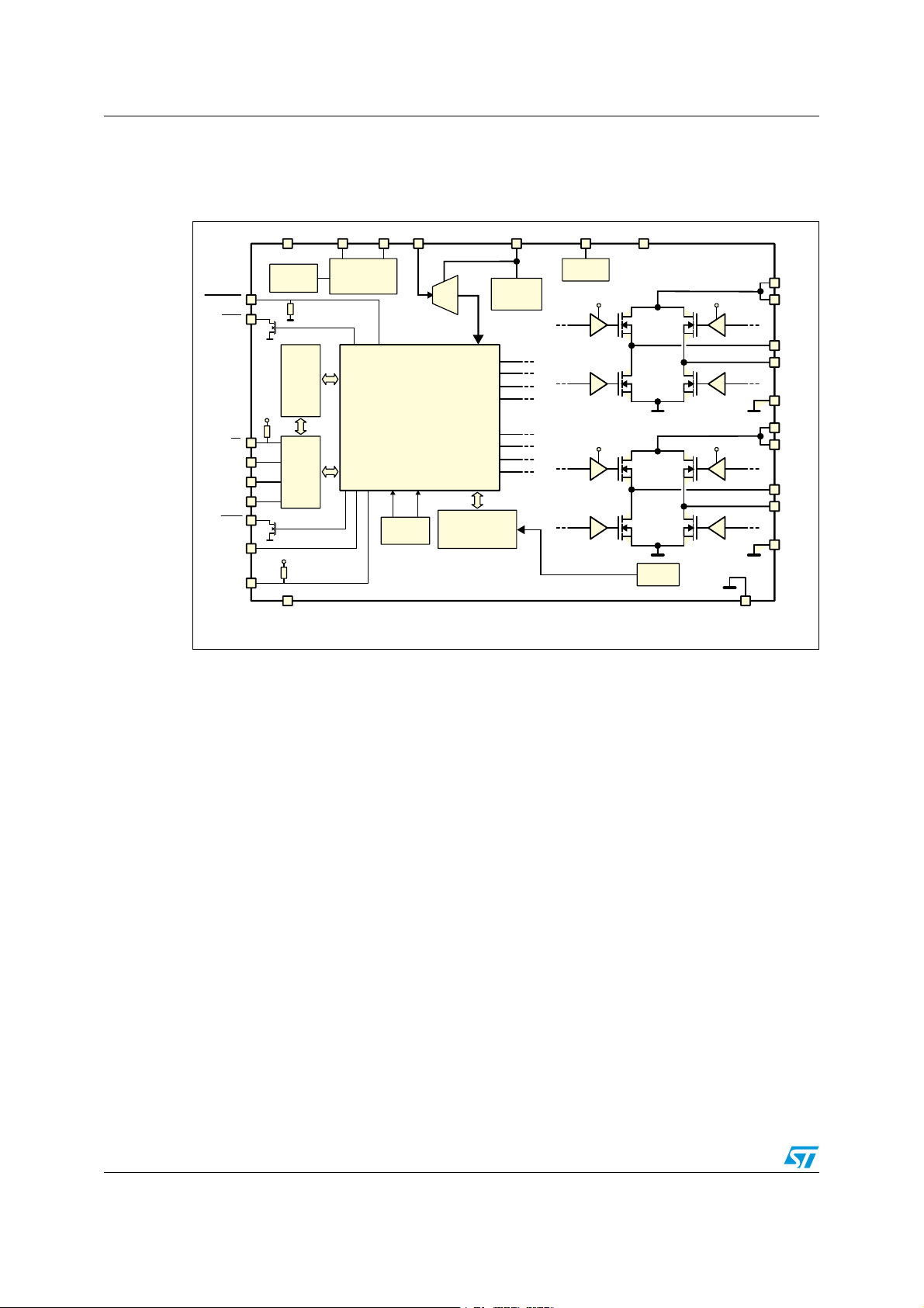
1 Block diagram
Figure 1. Block diagram
6$
$ /3#). /3 4//"60#'%26.)#$!45/#
34"9234
&,!'
3$/
3$)
"53939.#
34#+
37
(3
,3
(3
,3
#HARGE
PUMP
!
!
"
"
63!
6
BOOT
6
BOOT
#URRENT
SENSING
6
BOOT
(3
,3
6
BOOT
(3
,3
!'.$
63!
!
/54!
/54!
!
0'.$
63"
63"
"
/54"
/54"
"
0'.$
-(Z
/SCILLATOR
6
$$
#3
#+
%XT/SCDRIVER
2EGISTERS
#LOCKGEN
#ONTROL
,OGIC
!$#
6
6OLTAGE2EG
(3
!
,3
!
(3
!
,3
!
(3
"
,3
"
(3
"
,3
"
30)
#URRENT$!#S
#OMPARATORS
6
$$
$'.$
4EMPERATURE
SENSING
!-V
8/69 Doc ID 022729 Rev 1
L6472 Electrical data
2 Electrical data
2.1 Absolute maximum ratings
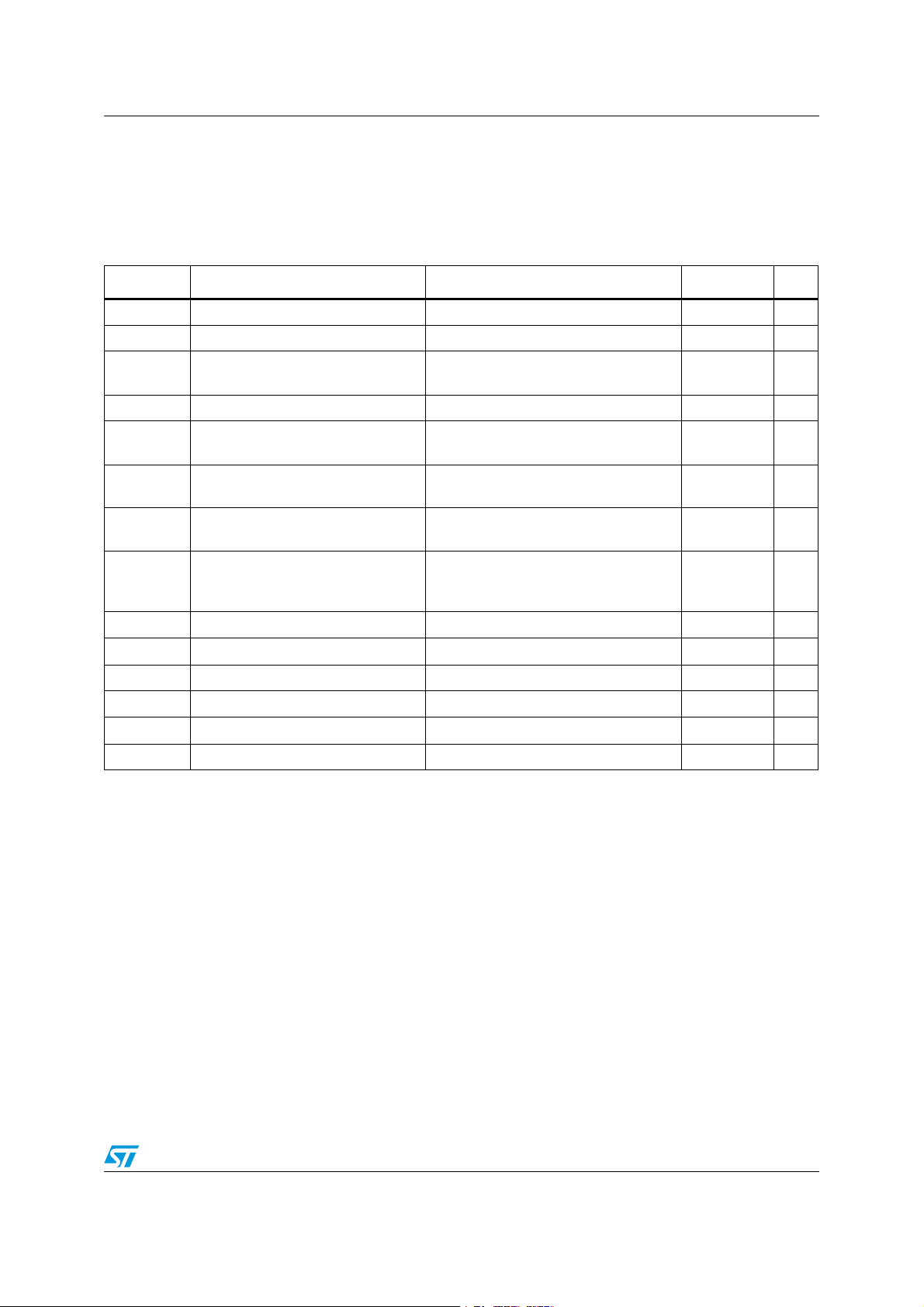
Table 2. Absolute maximum ratings
Symbol Parameter Test condition Value Unit
VDD Logic interface supply voltage 5.5 V
VS Motor supply voltage VSA = VSB = VS 48 V
Differential voltage between AGND,
V
V
V
V
I
out_peak
1. Maximum output current limit is related to metal connection and bonding characteristics. Actual limit must satisfy maximum
thermal dissipation constraints.
2. HTSSOP28 mounted on EVAL6472H Rev 1.0.
GND, diff
V
boot
V
REG
ADCIN
V
OSC
out_diff
LOGIC
I
out
T
OP
T
P
tot
PGND and DGND
Bootstrap peak voltage 55 V
Internal voltage regulator output pin
and logic supply voltage
Integrated ADC input voltage range
(ADCIN pin)
OSCIN and OSCOUT pin voltage
range
Differential voltage between V
, OUT2A, PGND and VSB,
OUT1
A
OUT1
, OUT2B, PGND pins
B
SA
,
= VSB = VS 48 V
V
SA
Logic inputs voltage range -0.3 to +5.5 V
(1)
R.m.s. output current 3 A
(1)
Pulsed output current T
< 1 ms 7 A
PULSE
Operating junction temperature 150 °C
Storage temperature range -55 to 150 °C
s
Total power dissipation (TA = 25 °C)
(2)
±0.3 V
3.6 V
-0.3 to +3.6 V
-0.3 to +3.6 V
5W
Doc ID 022729 Rev 1 9/69
Electrical data L6472
2.2 Recommended operating conditions
Table 3. Recommended operating conditions
Symbol Parameter Test condition Value Unit
V
Logic interface supply voltage
DD
V
Motor supply voltage VSA = VSB = VS 8 45 V
S
Differential voltage between
, OUT1A, OUT2A, PGND
V
V
out_diff
SA
and V
, OUT1B, OUT2B,
SB
PGND pins
V
Logic supply voltage
REG,in
Integrated ADC input voltage
V
ADC
(ADCIN pin)
Operating junction temperature -25 125 °C
T
j
2.3 Thermal data
Table 4. Thermal data
Symbol Parameter Package Typ Unit
R
thJA
1. HTSSOP28 mounted on EVAL6472H Rev 1.0 board: four-layer FR4 PCB with a dissipating copper surface
of about 40 cm
2. POWERSO36 mounted on EVAL6472PD Rev 1.0 board: four-layer FR4 PCB with a dissipating copper
surface of about 40 cm
Thermal resistance junction-ambient
2
on each layer and 15 via holes below the IC.
3.3 V logic outputs 3.3 V
5 V logic outputs 5
V
= V
= VS 45 V
SB
voltage imposed by
V
SA
REG
external source
2
on each layer and 22 via holes below the IC.
3.2 3.3 V
HTSSOP28
POWERSO36
0 V
(1)
(2)
22
12
REG
V
°C/W
10/69 Doc ID 022729 Rev 1
L6472 Electrical characteristics
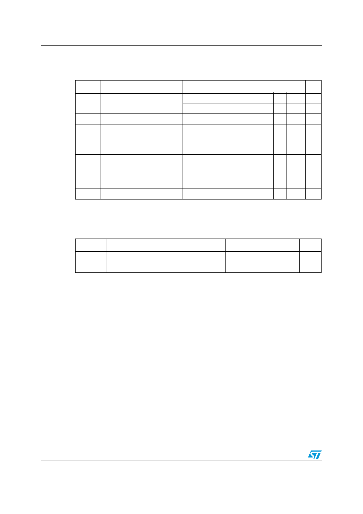
3 Electrical characteristics
VSA = VSB = 36 V; VDD = 3.3 V; internal 3 V regulator; TJ = 25 °C, unless otherwise
specified.
Table 5. Electrical characteristics
Symbol Parameter Test condition Min. Typ. Max. Unit
General
V
SthOn VS
V
SthOff
V
SthHyst
Iq
T
j(WRN)
T
j(SD)
UVLO turn-on threshold 7.5 8.2 8.9 V
VS UVLO turn-off threshold 6.6 7.2 7.8 V
VS UVLO threshold
hysteresis
Quiescent motor supply
current
Thermal warning temperature 130 °C
Thermal shutdown
temperature
Charge pump
pump
f
pump,min
f
pump,max
I
boot
pump oscillator
Minimum charge pump
oscillator frequency
Maximum charge pump
oscillator frequency
Average boot current
Voltage swing for charge
V
Output DMOS transistor
High-side switch onresistance
R
DS(on)
Low-side switch onresistance
I
DSS
Leakage current
(1)
(1)
0.7 1 1.3 V
Internal oscillator selected;
= 3.3V ext; CP floating
V
REG
= f
f
sw,A
= 15.6kHz
sw,B
POW_SR = ‘10’
T
= 25°C, I
j
Tj = 125°C,
= 25°C, I
T
j
T
= 125°C,
j
OUT = V
= 3A 0.37
out
(2)
I
= 3A 0.51
out
= 3A 0.18
out
(2)
I
= 3A 0.23
out
S
OUT = GND -0.3
0.5 0.65 mA
160 °C
10 V
660 kHz
800 kHz
1.1 1.4 mA
Ω
3.1
mA
Rise time
t
r
(3)
POW_SR = '00', I
POW_SR = '00', I
POW_SR = ‘11’, I
POW_SR = ‘10’, I
POW_SR = ‘01’, I
= +1A 100
out
= -1A 80
out
= ±1A 100
out
= ±1A 200
out
= ±1A 300
out
ns
Doc ID 022729 Rev 1 11/69
Electrical characteristics L6472
Table 5. Electrical characteristics (continued)
Symbol Parameter Test condition Min. Typ. Max. Unit
(3)
SR
SR
t
Fall time
f
Output rising slew rate
out_r
Output falling slew rate
out_f
Dead time and blanking
POW_SR = '00'; I
POW_SR = '00'; I
POW_SR = ‘11’, I
POW_SR = ‘10’, I
POW_SR = ‘01’, I
POW_SR = '00', I
POW_SR = '00', I
POW_SR = ‘11’, I
POW_SR = ‘10’, I
POW_SR = ‘01’, I
POW_SR = '00', I
POW_SR = '00', I
POW_SR = ‘11’, I
POW_SR = ‘10’, I
POW_SR = ‘01’, I
= +1A 90
out
= -1A 110
out
= ±1A 110
out
= ±1A 260
out
= ±1A 375
load
= +1A 285
out
= -1A 360
out
= ±1A 285
out
= ±1A 150
out
= ±1A 95
out
= +1A 320
out
= -1A 260
out
= ±1A 260
out
= ±1A 110
out
= ±1A 75
out
POW_SR = '00' 250
ns
V/µs
V/µs
t
t
blank Blanking time
DT
Dead time
Source-drain diodes
High-side diode forward ON
V
SD,HS
V
SD,LS
t
rrHS
voltage
Low-side diode forward ON
voltage
High-side diode reverse
recovery time
(1)
(1)
POW_SR = ‘11’,
= 16MHz
f
OSC
POW_SR = ‘10’,
f
= 16MHz
OSC
POW_SR = ‘01’,
= 16MHz
f
OSC
375
625
875
POW_SR = '00' 250
POW_SR = ‘11’,
= 16MHz
f
OSC
POW_SR = ‘10’,
= 16MHz
f
OSC
POW_SR = ‘01’,
f
= 16MHz
OSC
= 1A 1 1.1 V
I
out
I
= 1A 1 1.1 V
out
= 1A 30 ns
I
out
375
625
875
ns
ns
12/69 Doc ID 022729 Rev 1
L6472 Electrical characteristics
Table 5. Electrical characteristics (continued)
Symbol Parameter Test condition Min. Typ. Max. Unit
t
rrLS
Low-side diode reverse
recovery time
= 1A 100 ns
I
out
Logic inputs and outputs
Low logic level input voltage 0.8 V
V
IL
V
High logic level input voltage 2 V
IH
I
IIL
VOL
VOH High logic level output voltage
High logic level input current
(4)
IH
Low logic level input current
(5)
Low logic level output voltage
(6)
VIN = 5V 1 µA
V
= 0V -1 µA
IN
VDD = 3.3V, IOL = 4mA 0.3
= 5V, IOL = 4mA 0.3
V
DD
V
= 3.3V, IOH = 4mA 2.4
DD
VDD = 5V, IOH = 4mA 4.7
R
R
I
logic
I
logic,STBY
CS pull-up and STBY pull-
PU
down resistors
PD
Internal logic supply current
Standby mode internal logic
supply current
CS
= GND;
STBY/RST
3.3V V
= 5V
externally
REG
supplied, internal oscillator
3.3V V
externally supplied 2 2.5 µA
REG
335 430 565 kΩ
3.7 4.3 mA
V
V
f
Step-clock input frequency 2 MHz
STCK
Internal oscillator and external oscillator driver
Internal oscillator frequency T
f
osc,i
f
osc,e
V
OSCOUT
V
OSCOUTL
t
rOSCOUT
t
fOSCOUT
t
extosc
t
intosc
Programmable external
oscillator frequency
OSCOUT clock source high
level voltage
H
OSCOUT clock source low
level voltage
OSCOUT clock source rise
and fall time
Internal to external oscillator
switching delay
External to internal oscillator
switching delay
= 25°C, V
j
Internal oscillator 3.3V V
externally supplied; I
= 4mA
Internal oscillator 3.3V V
externally supplied; I
= 4mA
Internal oscillator 20 ns
SPI
Maximum SPI clock
f
CK,MAX
frequency
(7)
= 3.3V -3% 16 +3% MHz
REG
8 32 MHz
REG
OSCOUT
REG
OSCOUT
2.4 V
0.3 V
3 ms
1.5 µs
5 MHz
Doc ID 022729 Rev 1 13/69
Electrical characteristics L6472
Table 5. Electrical characteristics (continued)
Symbol Parameter Test condition Min. Typ. Max. Unit
t
rCK
t
fCK
t
hCK
t
lCK
t
setCS
t
holCS
t
disCS
t
setSDI
t
holSDI
t
enSDO
t
disSDO
t
vSDO
t
holSDO
SPI clock rise and fall time
SPI clock high and low time
(7)
Chip select setup time
Chip select hold time
De-select time
Data input setup time
Data input hold time
Data output enable time
Data output disable time
Data output valid time
Data output hold time
Switch input (SW)
R
PUSW
SW input pull-up resistance SW = GND 60 85 110 kΩ
Current control
I
STEP,max
Max. programmable
reference current
(7)
(7)
CL = 30pF 25 ns
75 ns
(7)
(7)
350 ns
10 ns
800 ns
(7)
(7)
(7)
(7)
(7)
(7)
37 ns
25 ns
20 ns
38 ns
47 ns
57 ns
4 A
I
STEP,min
Min. programmable reference
current
Overcurrent protection
Maximum programmable
I
OCD,MAX
overcurrent detection
threshold
Minimum programmable
I
OCD,MIN
overcurrent detection
threshold
I
OCD,RES
t
OCD,Flag
t
OCD,SD
Programmable overcurrent
detection threshold resolution
OCD to flag signal delay time dI
OCD to shutdown delay time
Standby
Quiescent motor supply
I
qSTBY
t
STBY,min
t
logicwu
current in standby conditions
Minimum standby time 10 µs
Logic power-on and wake-up
time
31 mA
OCD_TH = ‘1111’ 6 A
OCD_TH = ‘0000’
= 350A/µs 650 1000 ns
out/dt
= 350A/µs POW_SR =
dI
out/dt
'10'
= 8V 26 34
V
S
S = 36V 30 36
V
0.37
5
0.37
5
A
A
600 µs
µA
38 45 µs
14/69 Doc ID 022729 Rev 1
L6472 Electrical characteristics
Table 5. Electrical characteristics (continued)
Symbol Parameter Test condition Min. Typ. Max. Unit
t
cpwu
Charge pump power-on and
wake-up time
Power bridges disabled, Cp =
10nF, C
= 220nF
boot
Internal voltage regulator
REG
I
REG
V
REG, drop
I
REG,STBY
voltage
Voltage regulator output
current
Voltage regulator output
voltage drop
Voltage regulator standby
output current
= 40mA 50 mV
I
REG
Voltage regulator output
V
Integrated analog-to-digital converter
Analog-to-digital converter
N
ADC
V
ADC,ref
1. Accuracy depends on oscillator frequency accuracy.
2. Tested at 25 °C in a restricted range and guaranteed by characterization.
3. Rise and fall time depends on motor supply voltage value. Refer to SR
actual rise and fall time.
4. Not valid for the STBY/RST
5. Not valid for the SW and CS pins which have an internal pull-up resistor.
6. FLAG
7. See Figure 20 – SPI timings diagram for details.
resolution
Analog-to-digital converter
reference voltage
Analog-to-digital converter
f
S
sampling frequency
pin which has an internal pull-down resistor.
, BUSY and SYNC open drain outputs included.
out
650 µs
2.9 3 3.2 V
40 mA
10 mA
5 bit
V
V
REG
f
/
OSC
512
values in order to evaluate the
kHz
Doc ID 022729 Rev 1 15/69

Pin connection L6472
4 Pin connection
Figure 2. HTSSOP28 pin connection (top view)
345
Figure 3. POWERSO36 pin connection (top view)
74"
74"
48
&1"%
1(/%
065"
065"
45#:345
"%$*/
73&(
04$*/
04$065
"(/%
$1
7#005
065#
065#
74#
74#
065"
065"
74"
74"
45$,
'-"(
$4
#64:=4:/$
%(/%
4%*
$,
4%0
7%%
74#
74#
065#
065#
1(/%
16/69 Doc ID 022729 Rev 1
L6472 Pin connection
4.1 Pin list
Table 6. Pin description
No. Name Type Function
17 VDD Power Logic output supply voltage (pull-up reference)
6 VREG Power
7 OSCIN Analog input
Internal 3 V voltage regulator output and 3.3 V external logic
supply
Oscillator pin 1. To connect an external oscillator or clock source.
If this pin is unused, it should be left floating.
Oscillator pin 2. To connect an external oscillator. When the
8 OSCOUT Analog output
internal oscillator is used this pin can supply 2/4/8/16 MHz. If this
pin is unused, it should be left floating.
10 CP Output Charge pump oscillator output
11 Vboot Supply voltage
Bootstrap voltage needed for driving the high-side power DMOS of
both bridges (A and B)
5 ADCIN Analog input Internal analog-to-digital converter input
2
VSA Power supply Full bridge A power supply pin. It must be connected to VSB
26
12
VSB Power supply Full bridge B power supply pin. It must be connected to VSA
16
27
PGND Ground Power ground pin
13
1 OUT1A Power output Full bridge A output 1
28 OUT2A Power output Full bridge A output 2
14 OUT1B Power output Full bridge B output 1
15 OUT2B Power output Full bridge B output 2
9 AGND Ground Analog ground.
4 SW Logical input
External switch input pin. If not used the pin should be connected
to VDD.
21 DGND Ground Digital ground
By default, this BUSY pin is forced low when the device is
22 BUSY
\SYNC Open drain output
performing a command. Otherwise the pin can be configured to
generate a synchronization signal.
18 SDO Logic output Data output pin for serial interface
20 SDI Logic input Data input pin for serial interface
19 CK Logic input Serial interface clock
23 CS
Logic input Chip select input pin for serial interface
Status flag pin. An internal open drain transistor can pull the pin to
24 FLAG Open drain output
GND when a programmed alarm condition occurs (step loss,
OCD, thermal pre-warning or shutdown, UVLO, wrong command,
non-performable command)
Doc ID 022729 Rev 1 17/69

Pin connection L6472
Table 6. Pin description (continued)
No. Name Type Function
Standby and reset pin. LOW logic level resets the logic and puts
3 STBY\RST Logic input
25 STCK Logic input Step-clock input
EPAD Exposed pad Ground Internally connected to PGND, AGND and DGND pins
the device into standby mode. If not used, it should be connected
to VDD
18/69 Doc ID 022729 Rev 1
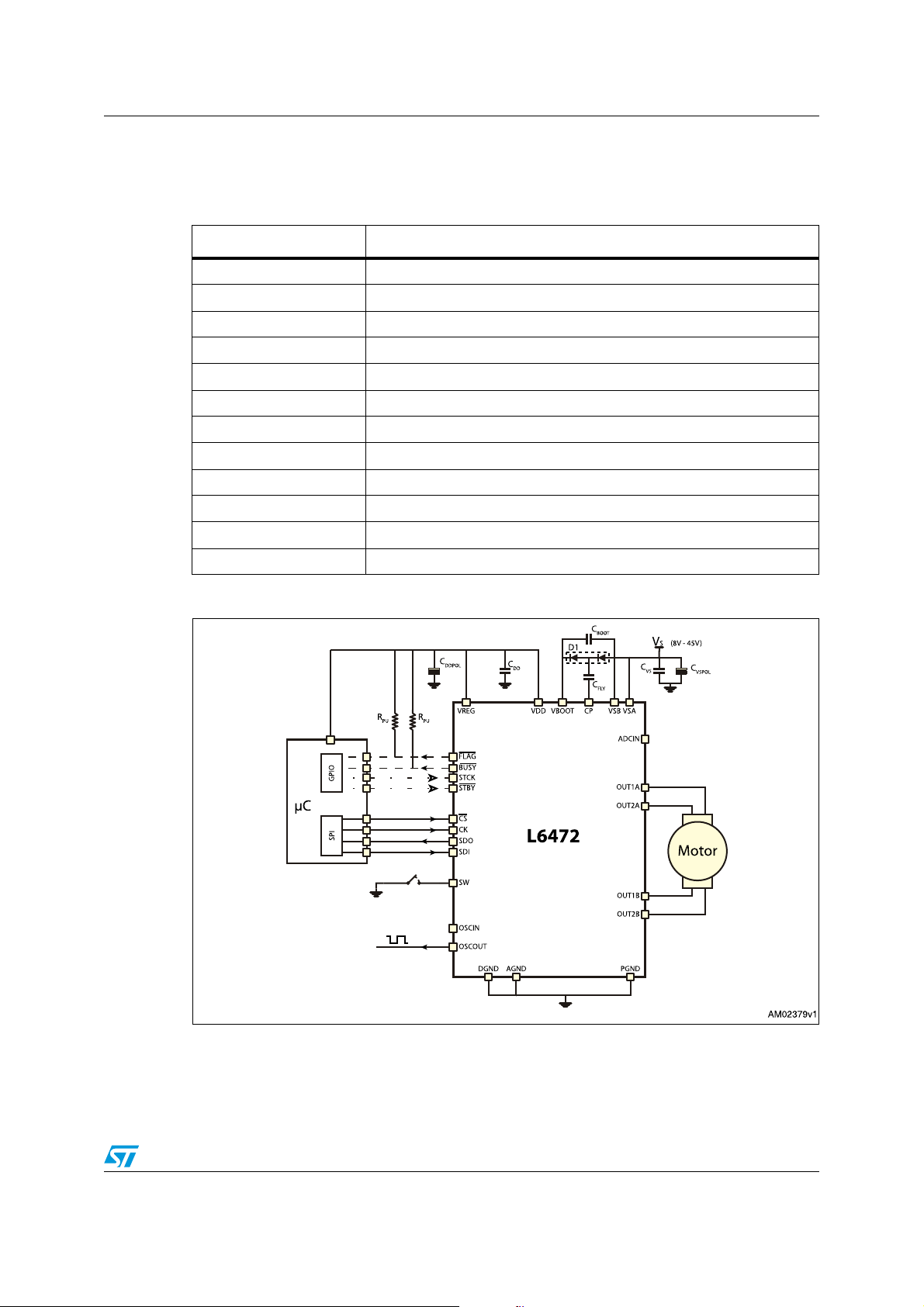
L6472 Typical applications
5 Typical applications
Table 7. Typical application values
Name Value
220 nF
C
VS
C
C
C
100 µF
VSPOL
C
100 nF
REG
REGPOL
47 µF
C
100 nF
DD
10 µF
DDPOL
D1 Charge pump diodes
C
220 nF
BOOT
C
10 nF
FLY
R
39 kΩ
PU
R
100 Ω
SW
CSW 10 nF
Figure 4. Bipolar stepper motor control application using the L6472
Doc ID 022729 Rev 1 19/69

Functional description L6472
6 Functional description
6.1 Device power-up
At the end of power-up, the device state is the following:
● Registers are set to default,
● Internal logic is driven by the internal oscillator and a 2 MHz clock is provided by the
OSCOUT pin,
● Bridges are disabled (High Z),
● UVLO bit in the STATUS register is forced low (fail condition),
● FLAG output is forced low.
During power-up the device is under reset (all logic IO disabled and power bridges in highimpedance state) until the following conditions are satisfied:
● V
●
● Internal oscillator is operative.
Any motion command causes the device to exit from High Z state (HardStop and SoftStop
included).
is greater than V
S
V
is greater than V
REG
SthOn
REGth
= 2.8 V (typ.)
6.2 Logic I/O
Pins CS, CK, SDI, STCK, SW and STBY\RST are TTL/CMOS 3.3 V-5 V compatible logic
inputs.
Pin SDO is a TTL/CMOS compatible logic output. The VDD pin voltage sets the logic output
pin voltage range; when it is connected to VREG or a 3.3 V external supply voltage, the
output is 3.3 V compatible. When VDD is connected to a 5 V supply voltage, SDO is 5 V
compatible.
VDD is not internally connected to V
A 10 µF capacitor should be connected to the VDD pin in order to obtain a proper operation.
Pins FLAG
and BUSY\SYNC are open drain outputs.
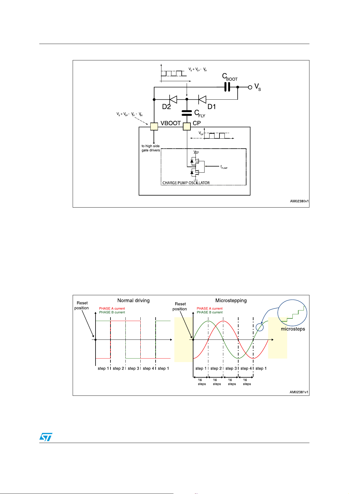
6.3 Charge pump
To ensure the correct driving of the high-side integrated MOSFETs, a voltage higher than
the motor power supply voltage needs to be applied to the Vboot pin. The high-side gate
driver supply voltage Vboot is obtained through an oscillator and a few external components
realizing a charge pump (see Figure 5).
, an external connection is always needed.
REG
20/69 Doc ID 022729 Rev 1
L6472 Functional description
Figure 5. Charge pump circuitry
6.4 Microstepping
The driver is able to divide the single step into up to 16 microsteps. Step mode can be
programmed by the STEP_SEL parameter in the STEP_MODE register (see Ta b le 1 9 ).
Step mode can only be changed when bridges are disabled. Every time step mode is
changed, the electrical position (i.e. the point of microstepping sinewave that is generated)
is reset to the first microstep, and the absolute position counter value (see Section 6.5)
becomes meaningless.
Figure 6. Normal mode and microstepping (16 microsteps)
Doc ID 022729 Rev 1 21/69
 Loading...