How it Works
Log In / Sign Up
Buy Points
How it Works
FAQ
Contact Us
Questions and Suggestions
Users
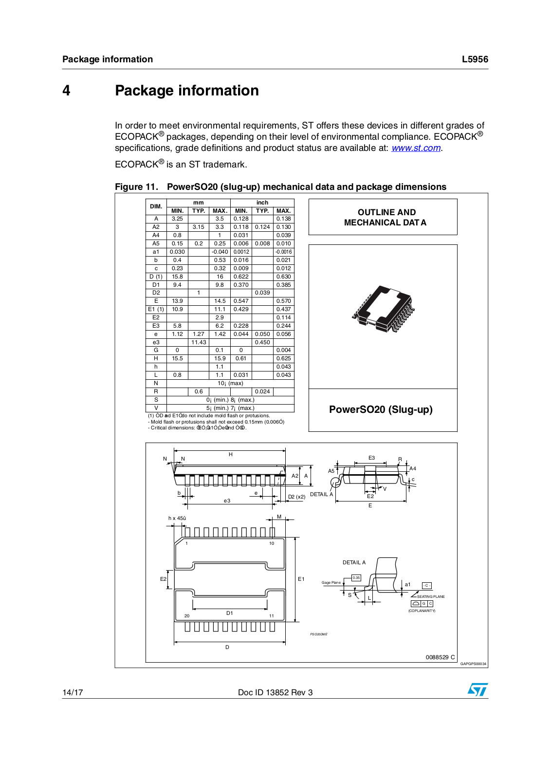
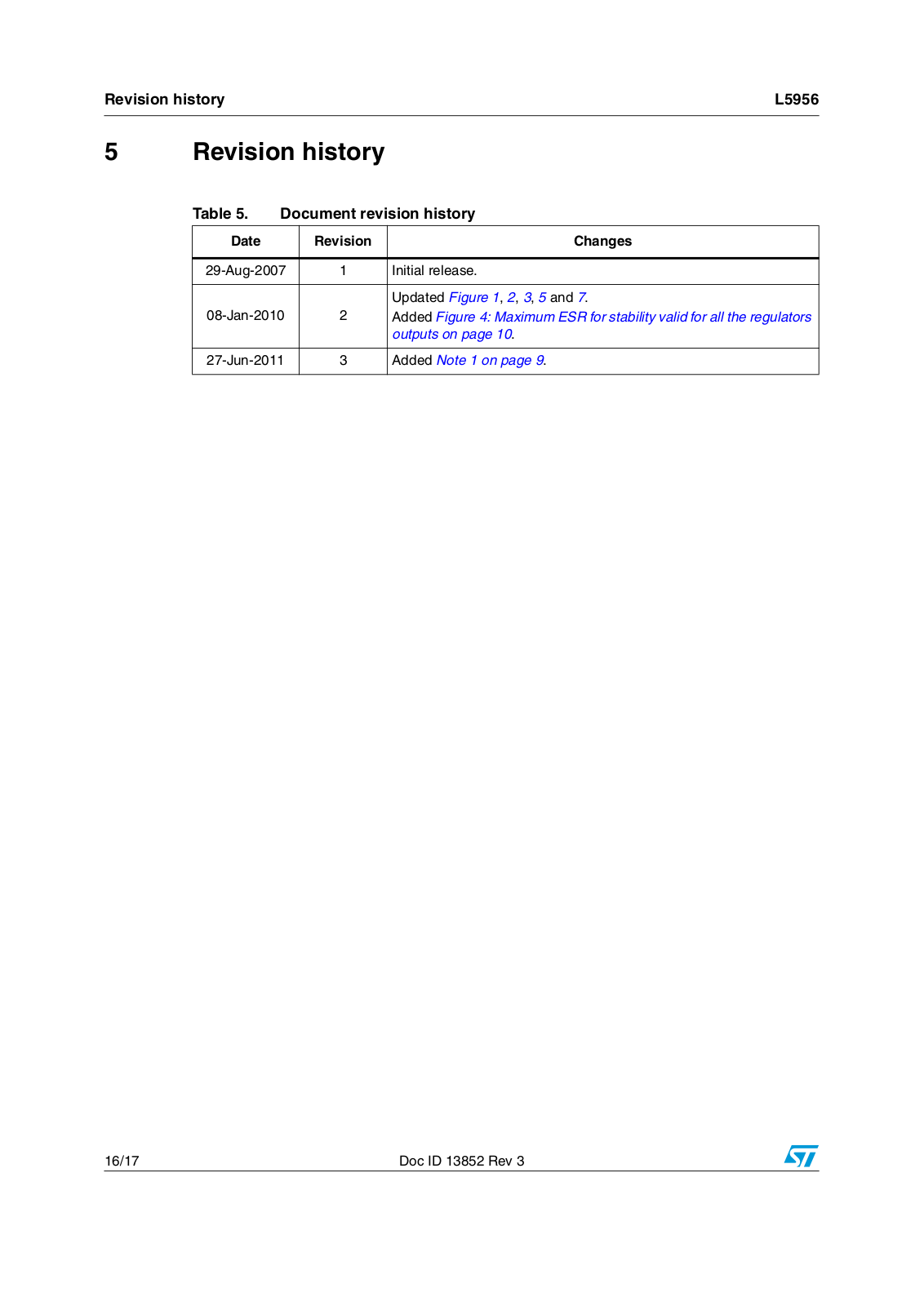
Datasheet
Loading...
L
L53SED
L53SET
L53SF4BT
L53SF4C
L53SGD12V
2
L53SRC
L53SRC-DU
2
L53SRC-DV
2
L53SRC-DW
2
L53SRD
L53SRD-G
2
L53SRD-H
2
L53SRSGW
L53SURC
L53SURC-E
L53SYC
2
L53SYD
L53SYT
L53YC
L53YD
L53YDTNR254
L53YDTNR5-7
L53YT
L54
L5431
2
L55
L5502-11
L5586
L56
L56BGD
L56BHD
L56BSRD-B
2
L56BYD
L57
L5766
L57EGW
L57EYW
L57GGD
L57GYW
L57IID
L57SRSRD
L57YYD
L58
L584
L585
L5871
L59
L5950
L5951
L5955
L5956
L5957
L5958
L5959
L5962
L5970AD
L5970D
2
L5971
L5971D
L5972D
2
L5973AD
2
L5973D
2
L5980
L5981
L5983
L5985
L5986
L5987
L5988D
L5989D
L5991
2
L5991A
2
L5991AD
L5991D
2
L5993
L5993D
L5994
L5996
L59BL-EGW
L59BL-EYW
L59BL-GYW
L59CB-EGW
L59CB-EYW
L59CB-GYW
L59EGC
L59EGW
L59EGW-CA
2
L59EGWTNB254
L59EYC
L59EYW
L59EYWTNB254
L59GYC
L59GYW
L59GYWTNB254
L59SRSGC-CC
L59SRSGW-CC
L59SURKMGKW
L59SURKSGC
L5LEGW12.3S
L5LEYW12.3S
Loading...
Loading...
Nothing found
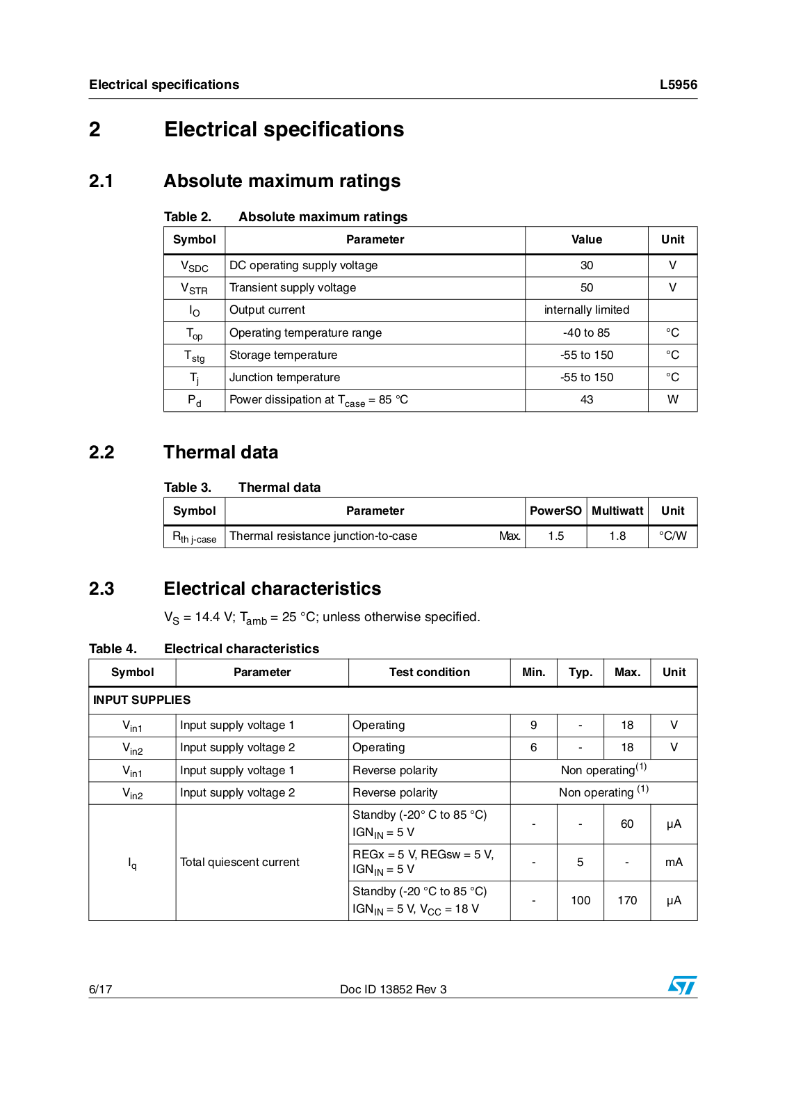
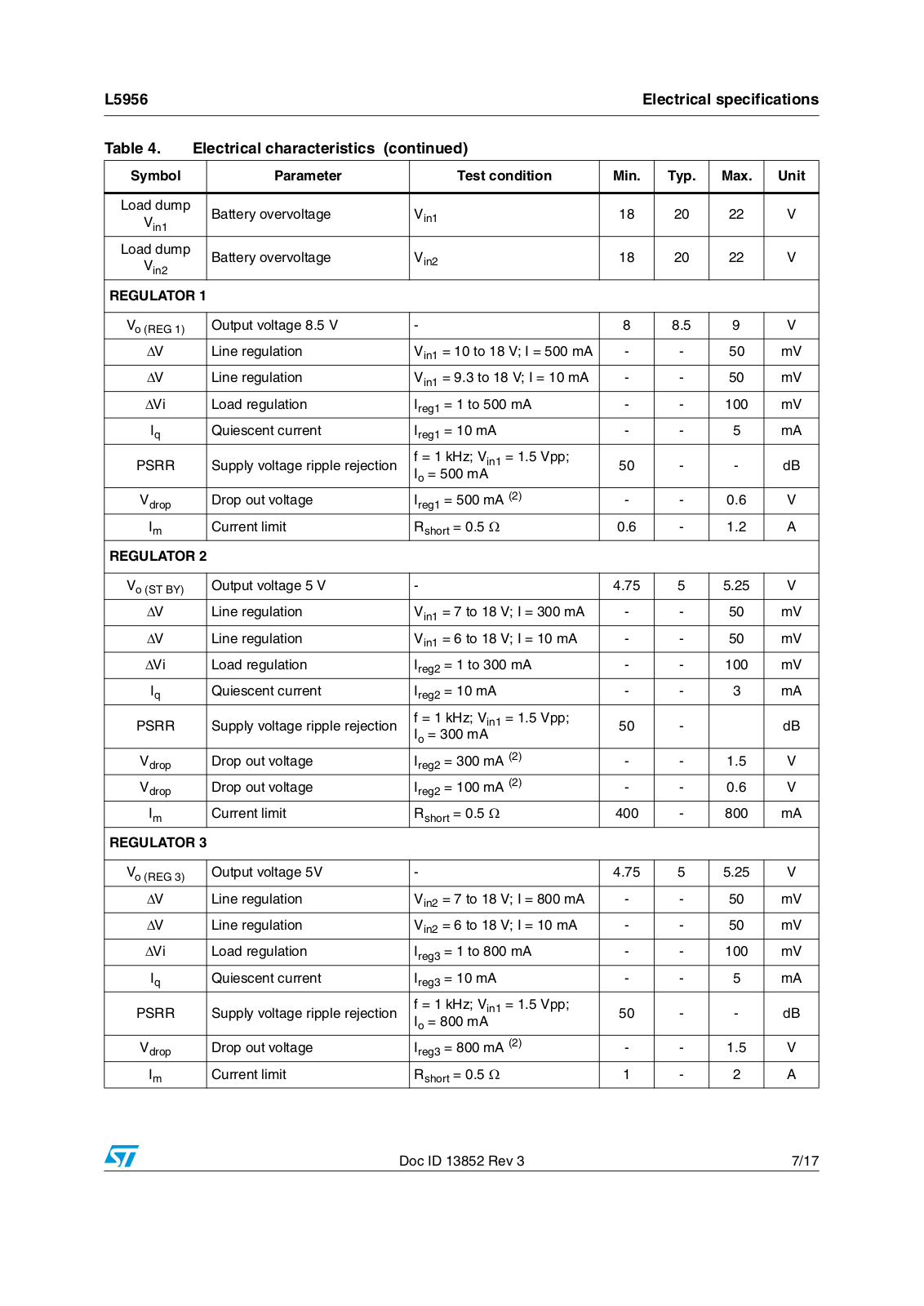
L5956
Datasheet (ST)
17 pgs
292.39 Kb
0
Table of contents
Loading...
Datasheet L5956 Datasheet (ST)
...
Datasheet Datasheet (ST)
Download
Specifications and Main Features
Frequently Asked Questions
User Manual
Download
Loading...
+
hidden pages
Unhide
You need points to download manuals.
1 point = 1 manual.
You can buy points or you can get point for every manual you upload.
Buy points
Upload your manuals
 Loading...

")