

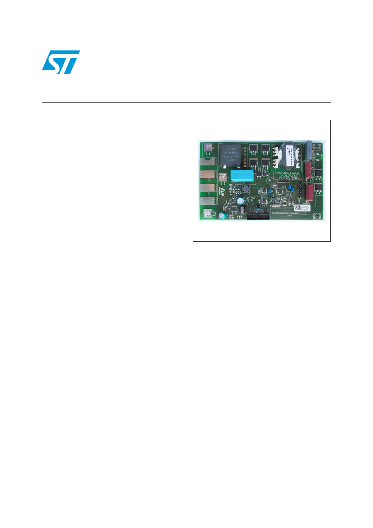
250 W DC-DC solar module demonstration board
Features
■ Input voltage range from 10 V to 45 V
■ Output voltage range from 350 V to 430 V
■ Digital control section managed by the STM32
■ Several I/O connectors to be connected to the
photovoltaic panel (input side) and the inverter
(output side)
■ Ready to be connected to a PLM or ZigBee
external module for communication
■ Possibility to meter and monitor the status of
the panel
■ Fire and anti-theft protections
■ RoHS compliant
Description
The STEVAL-ISV013V1 demonstration board is a
fully integrated module designed for a smart
junction box in distributed photovoltaic
architecture. The module represents an easy-touse, fully-protected solution to implement precise
photovoltaic panel control, diagnostics and
protection.
The STEVAL-ISV013V1 demonstration board is
the base element for a new photovoltaic panel
configuration able to increase the panel energy
produced and to simplify the photovoltaic field
design and implementation. Furthermore, the
maintenance cost will be reduced as the device is
able to monitor the status of the individual panels
and to communicate these data to a remote
control unit. The STEVAL-ISV013V1
demonstration board uses an isolated converter,
which is the input of the panel output. This voltage
is stepped up to the voltage defined by the
inverter, needed to create a sinusoidal output with
a magnitude big enough to transfer energy to the
grid.
STEVAL-ISV013V1
for distributed photovoltaic architecture
Data brief
®
STEVAL-ISV013V1
STEVAL-ISV013V1
search for the best operating point of the panel in
order to maximize the energy produced in every
environmental condition.
The module is internally protected from a surge or
lightning reaching the connection wires.
The STEVAL-ISV013V1 demonstration board
includes a PLM or ZigBee
communication. The PLM is supported by a
proprietary protocol stack for networking. A
gateway to RS485 in modbus is available. The
unit is designed to operate in a harsh
environment, offering a high level of protection
and very high reliability.
The ZigBee
®
module is based on system-on-chip
(SoC) technology, integrating both IEEE 802.15.4
radio transceiver and computing capabilities and
is designed to run a fully compliant ZigBee
network protocol stack.
®
module for
®
PRO
The module features an embedded MPPT
(maximum power point tracking) algorithm based
on the “perturb and observe” (P&O) technique to
September 2011 Doc ID 022189 Rev 1 1/5
For further information contact your local STMicroelectronics sales office.
www.st.com
5
Schematic circuit STEVAL-ISV013V1
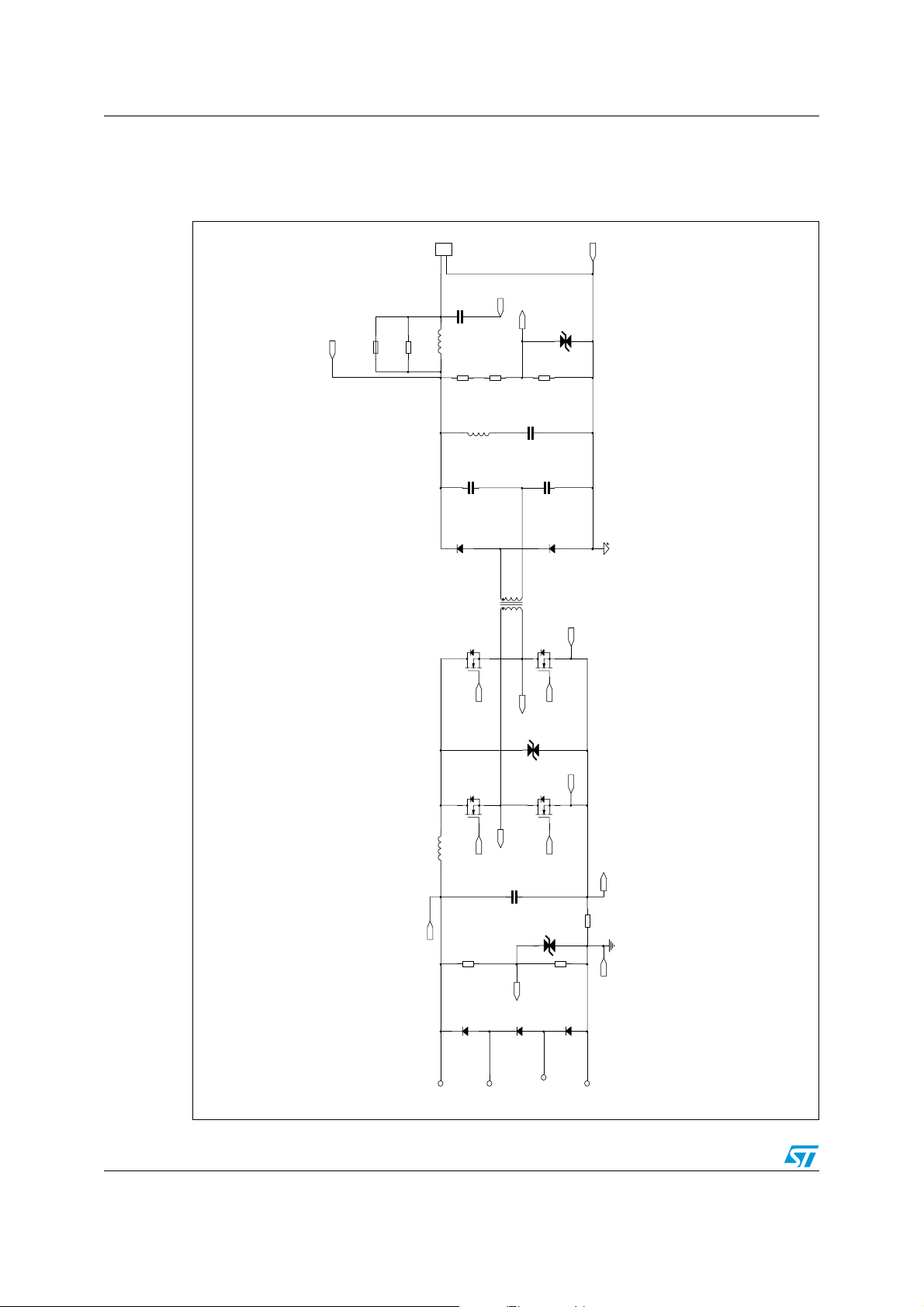
1 Schematic circuit
Figure 1. Isolated full-bridge boost converter
J2
CON2
2
1
C1
9x26.5
p.22.5
VOUT+_EXT
0.22u 630V
1206
F1
VOUT+
FUSE
R116
0 ohm
L5
N.M.
R2
7.5M 1%
D2PAK
D1
STTH12R06G
Vbus_SENS
1206
1206
R3
7.5M 1%
C82
6.3x6.3
10uH
L6
C2
2.2u 250V
TR1
H2PAKH2PAK
STH180N10F3-2
Q4
10n 630V
Voltage max 205V to GN D
10,11,12
7,8,9
1,2,3
4,5,6
Voltage max 50V
VOUT-
N.M.
D18
51K 1%
R5
0603
1210
C4
2.2u 250V
D3
STTH12R06G
D2PAK
H2PAK
Q2
STH180N10F3-2
SOURCE2
8,9,10,12,13,14
L1
1,2,3,5,6,7
VINPUT
1
J1+
2/5 Doc ID 022189 Rev 1
GATE 4
Q3
STH180N10F3-2
80uH, 8A
Out1
GATE 3
150K 1%
R1
1206
D32
SPV1001D40
1
J-SPARE1
GATE 2
Out2
D2
SMBJ70CA
SMB
H2PAK
Q1
STH180N10F3-2
SOURCE1
Voltag e max 50V
GATE 1
C3
22u 100V
D8
N.M.
Voltage max 3.3V
VIN_SENS_PV
D31
1
SPV1001D40
J-SPARE2
I_SENS_PV+
R6
3m Ohm
0805/SMB
I_SENS_PV-
R4
4.7K 1%
0603/0805
D30
SPV1001D40
1
J1-
AM10164V1

STEVAL-ISV013V1 Schematic circuit
Figure 2. Auxiliary power supply
VCC
5V
25V
1206/0805
C8
10u
R18
1K
D10
5.1V
1206
SOD123/323
N.M.
R21
L2
22uH
6.3x6.3
SMB/SMA
D4
STPS2H100
VOUT+
910K
R9
1206
R14
910K
1206
R8
5.1M
1206
1206
R13
5.1M
1206
1206
R12
1.5M
R7
1.5M
GND
10n
C6
1M
R17
?
C5
5.1M
R15
R11
1206
5.1M
630V
C7
100p
R16
1.5M
R10
1.5M
1206
0805/0603
25V
22u
C12
1210
12061206
R26
62 ohm
250V
C10
470p
0805/0603
R25
62 ohm
2
1
TR2
5
6
D5
D12
SMAJ70
STTH1R06A
C15
?
2.7M
R20
R24
620K 1%
TS432
IC13
51K
R23
C11
?
D7
TS821
C9
C14
?
?
3
4
+
-
2
5
1
IC1A
TS7221
D11
1N4148
R19
150K
1206
Q6
1206
MMBTA42
1206
GND
0805
250V
C13
10n
Q5
STN1HNK60
N.M.
SMA
D6
12x12
L3
1mH
SMB
D9
R22
N.M. 1206
STTH3L06U
VINPUT
3.3V
GND
GND
2
JP2
GND
1
1
2
3.3V
JP1
1206/0805
C20
10u 16V
3
sot89
2
OUTPUT
GND
INPUT
IC4
LD2981ABU33TR
1
10K
R32
0805/1206
C19
10u 16V
SMA
D13
STPS1L60
TR2
4
3
.
C26
470p
C18
100n
100V
1206/0805
R30
10K
1206
10K
R113
1206
SOD123/323
D15
D14
BAT48
BAT48
1206
1206
R29
750 ohm
750 ohm
R28
R112
R27
300K
1206
C81
N.M.
2220/1210
C17
100V
2.2u
2220/1210
D33
N.M.
SMA/SMB
6x6?
L7
N.M.
C16
33u
100V
1206
N.M.
R114
Q7
MMBTA42
C24
100n
6
7
8
1.5K 1%
VI
OUT
VREF
COMP
VFB
ISENSE
IC2
2
1
3
C22
10n
R33
100K
10n
C21
R35
GND
R34
120K 1%
C23
10n
R31
300K
1206
C80
N.M.
DIAM 8 e 12.5
1210
R115
0 ohm
1206
R40
220 ohm
250V
0805/0603
1206
R39
220 ohm
R43
1206
0.22 ohm
470K
Q8
DPAK
STD20NF20
1206
R38
10 ohm
R45
0805
R42
470K
D17
1N4148
SOD123/323
Q10
BC847
R41
330K
R44
N.M.
Q9
BC847
C35
D16 N.M (SMA)
C25
47u
63V
DIAM 8 e 10
VINPUT
22K
R48
1206
?
1.8M
R51
R55
560K
IC14
TS432
5
Q11
GND
RT/CT
UC3843B
4
R37
27K
24K 1%
C29
4.7n
?
C30
240K
R49
GND
C27
33p
33p
C28
3.3K
R36
C31
100n
R47
110K 1%
1206
GND
1206
R46
110K 1 %
BC847
470K
220K
R50
R54
1
IC3A
TS7211
+
-
5
2
3
4
C34
?
?
C32
18K
R53
D19
TS821
18K
R52
GND
?
C33
AM10165V1
Doc ID 022189 Rev 1 3/5

Revision history STEVAL-ISV013V1
2 Revision history
Table 1. Document revision history
Date Revision Changes
07-Sep-2011 1 Initial release.
4/5 Doc ID 022189 Rev 1

STEVAL-ISV013V1
Please Read Carefully:
Information in this document is provided solely in connection with ST products. STMicroelectronics NV and its subsidiaries (“ST”) reserve the
right to make changes, corrections, modifications or improvements, to this document, and the products and services described herein at any
time, without notice.
All ST products are sold pursuant to ST’s terms and conditions of sale.
Purchasers are solely responsible for the choice, selection and use of the ST products and services described herein, and ST assumes no
liability whatsoever relating to the choice, selection or use of the ST products and services described herein.
No license, express or implied, by estoppel or otherwise, to any intellectual property rights is granted under this document. If any part of this
document refers to any third party products or services it shall not be deemed a license grant by ST for the use of such third party products
or services, or any intellectual property contained therein or considered as a warranty covering the use in any manner whatsoever of such
third party products or services or any intellectual property contained therein.
UNLESS OTHERWISE SET FORTH IN ST’S TERMS AND CONDITIONS OF SALE ST DISCLAIMS ANY EXPRESS OR IMPLIED
WARRANTY WITH RESPECT TO THE USE AND/OR SALE OF ST PRODUCTS INCLUDING WITHOUT LIMITATION IMPLIED
WARRANTIES OF MERCHANTABILITY, FITNESS FOR A PARTICULAR PURPOSE (AND THEIR EQUIVALENTS UNDER THE LAWS
OF ANY JURISDICTION), OR INFRINGEMENT OF ANY PATENT, COPYRIGHT OR OTHER INTELLECTUAL PROPERTY RIGHT.
UNLESS EXPRESSLY APPROVED IN WRITING BY TWO AUTHORIZED ST REPRESENTATIVES, ST PRODUCTS ARE NOT
RECOMMENDED, AUTHORIZED OR WARRANTED FOR USE IN MILITARY, AIR CRAFT, SPACE, LIFE SAVING, OR LIFE SUSTAINING
APPLICATIONS, NOR IN PRODUCTS OR SYSTEMS WHERE FAILURE OR MALFUNCTION MAY RESULT IN PERSONAL INJURY,
DEATH, OR SEVERE PROPERTY OR ENVIRONMENTAL DAMAGE. ST PRODUCTS WHICH ARE NOT SPECIFIED AS "AUTOMOTIVE
GRADE" MAY ONLY BE USED IN AUTOMOTIVE APPLICATIONS AT USER’S OWN RISK.
Resale of ST products with provisions different from the statements and/or technical features set forth in this document shall immediately void
any warranty granted by ST for the ST product or service described herein and shall not create or extend in any manner whatsoever, any
liability of ST.
ST and the ST logo are trademarks or registered trademarks of ST in various countries.
Information in this document supersedes and replaces all information previously supplied.
The ST logo is a registered trademark of STMicroelectronics. All other names are the property of their respective owners.
© 2011 STMicroelectronics - All rights reserved
Australia - Belgium - Brazil - Canada - China - Czech Republic - Finland - France - Germany - Hong Kong - India - Israel - Italy - Japan -
STMicroelectronics group of companies
Malaysia - Malta - Morocco - Philippines - Singapore - Spain - Sweden - Switzerland - United Kingdom - United States of America
www.st.com
Doc ID 022189 Rev 1 5/5
 Loading...