How it Works
Log In / Sign Up
Buy Points
How it Works
FAQ
Contact Us
Questions and Suggestions
Users
ST
Loading...
I
IPC002V1
IPC003V1
IPE002V1
IPE003V1
IPE004V1
IPE005V1
IPE007V1
IPE008V1
IPE009V1
IPE010V1
IPE010V2
IPE011V1
IPE012V1
IPE012V2
IPE014V1
IPE015V1
IPE017V1
IPE018V1
IPE020V1
IPP001V2
IPP002V1
IPR002V1
IPT002V1
ISA001V1
ISA005V1
ISA006V1
ISA007V1
ISA008V1
ISA009V1
ISA010V1
ISA011V1
ISA012V1
ISA013V1
ISA014V1
ISA015V2
ISA018V1
ISA019V3
ISA020V1
ISA023V2
ISA024V1
ISA025V1
ISA026V1
ISA027V1
ISA028V1
ISA029V1
ISA030V1
ISA031V1
ISA032V1
ISA033V1
ISA034V1
ISA035V1
ISA037V1
ISA038V1
ISA039V1
ISA042V2
ISA043V1
ISA044V2
ISA044V5
ISA044V6
ISA045V1
ISA045V2
ISA046V1
ISA046V2
ISA047V1
ISA047V2
ISA048V2
ISA049V1
ISA049V2
ISA050V1
ISA051V1
ISA051V2
ISA052V1
ISA052V2
ISA053V1
ISA053V2
ISA055V1
ISA056V1
ISA057V1
ISA058V1
ISA060V1
ISA063V1
ISA067V1
ISA068V1
ISA069V1
ISA070V1
ISA071V1
ISA071V2
ISA076V1
ISA076V2
ISA077V1
ISA077V2
ISA078V1
ISA079V1
ISA081V1
ISA082V1
ISA083V1
ISA084V1
ISA088V1
ISA089V1
ISA091V1
Loading...
Loading...
Nothing found
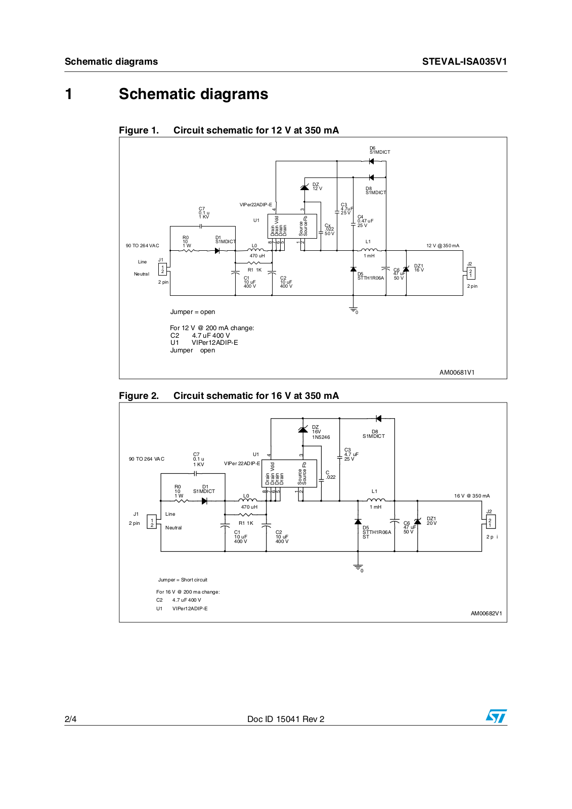
ISA035V1
User Manual
4 pgs
91.77 Kb
0
Table of contents
Loading...
ST ISA035V1 User Manual
...
ST User Manual
Download
Specifications and Main Features
Frequently Asked Questions
User Manual
Download
Loading...
+
hidden pages
Unhide
You need points to download manuals.
1 point = 1 manual.
You can buy points or you can get point for every manual you upload.
Buy points
Upload your manuals
 Loading...