

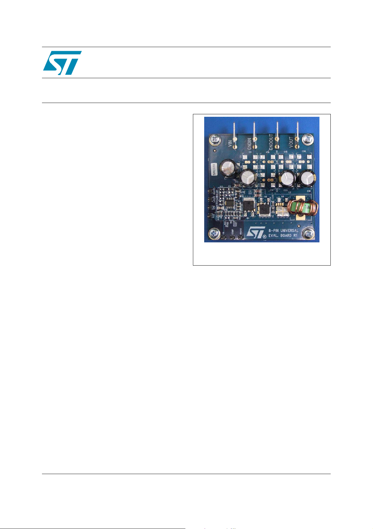
Single phase 20 A step-down converter evaluation board
Features
■ BOM optimized for 12 V input / 1.25 V output @
20 A
■ High flexibility to host wide range designs
■ Customizable output voltage
■ L6726A / L6727 compatibility
■ Controller input voltage (V
12 V
■ Conversion input voltage (V
■ DPAK / SO-8 / PowerSO-8 / PowerFLAT
MOSFET compatibility
■ Multi-footprint for input and output capacitors
■ Through-hole / SMD inductor compatibility
■ 4-layer PCB
Description
) range from 5 V to
CC
) up to 13.2 V
IN
STEVAL-ISA028V1
based on the L6727
Data Brief
STEVAL-ISA028V1
This evaluation board demonstrates the key
features of STMicroelectronics’ L6727, a new
powerful new buck controller. The L6727 makes
the design of complete step-down voltage
regulators simple and cost effective. It provides a
full solution by integrating a 0.8 V reference,
control logic and protection, and NMOS drivers in
an 8-pin package. The L6727 evaluation board
implements a step-down DC/DC converter in a
four-layer PCB and demonstrates the operation of
the device in a general-purpose application. The
input voltage can range from 5 V to 12 V and the
output voltage is fixed at 1.25 V. The application
can deliver an output current up to 20 A. Airflow
must be applied with current higher than 18 A
(@V
= 5 V). The switching frequency is 300 kHz.
IN
December 2007 Rev 2 1/4
For further information contact your local STMicroelectronics sales office
www.st.com
4
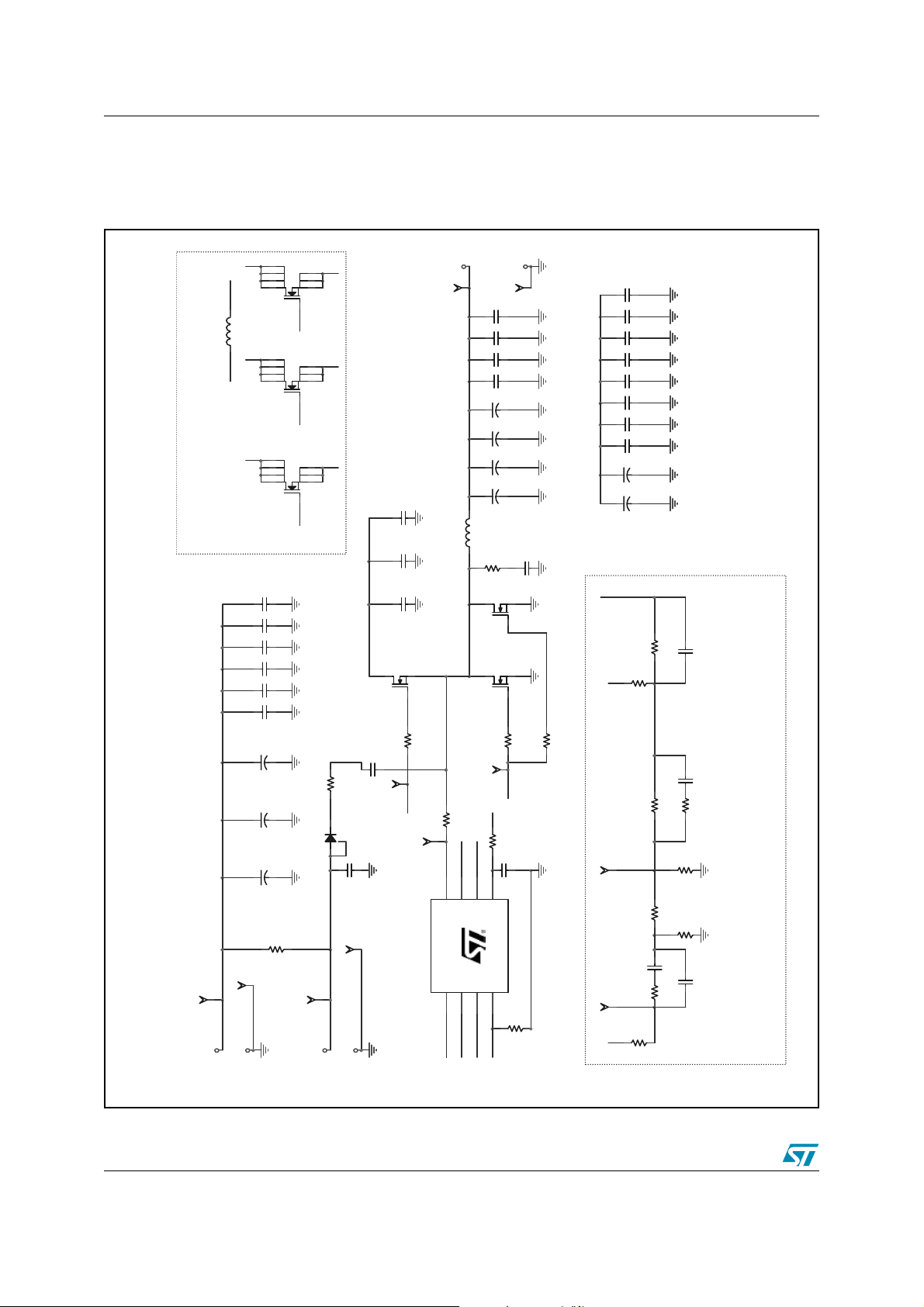
Board schematic STEVAL-ISA028V1
1 Board schematic
Figure 1. Schematic
PHASE
8
7
6
51
OUT
Q3
NC
L1
NC
1 2
PHASE
8
7
6
PHASE
51
Q2
NC
HSD
8
7
6
51
Q1
NC
NC
C9
NC
C8
NC
C7
NC
C6
NC
C5
NC
C4
C3
NC
C2
1800uF
C1
1800uF
R16
GNDIN1
VIN1
VIN_POWER
0
GNDIN_POWER
GND
3
2
4
LSG2
GND
3
2
4
LSG1
PHASE
3
2
100nF
C381uF
GND
VIN_POWER
HSDHSD
C10
C13
4.7uF
C12
4.7uF
C11
4.7uF
Q4
STD55NH2LL
1
HSG
R3
UGATE
UGATE
0
0
4
HSG
00 0
00 0
BOOT
R2
3.3
0 0
D1
1N4148
0
0
GND
VCC
VCC
GNDCC
VCC
VOUT
VOUT1
C22
C21
C20
C19
OUT
C18
C17
C16
C15
12
L2
T60-18 6Ts
1.8
0 0 0
3 2
2.2
PHASE
R17
PHASE
8
PHASE
Q6
Q5
LGATE R4
VCC
2.2
3.3
FB
COMP
1uF
VCC_PIN
5
7
6
FB
VCC
COMP
L6726A/27
GND
UGATE2BOOT
U1
1
BOOT
LGATE
3
4
LGATE
UGATE
GND
0
GNDOUT
GNDOU T1
0
NC
NC
NC
0 0 0
NC
0
2200uF
NC
0 0
NC
0
NC
C23
6.8nF
0
NC
0
3 2
1
STD90NH2LL
0
3 2
1
LSG1
R5
LGATELGATE
R1
NC
0
R15
C14
0
R18
NC
C34
NC
C33
NC
C32
NC
C31
C30
C29
OUT
C28
C27
C26
C25
PHASE
FB
COMP FB
VCC_PIN
0 0 0 0
NC
NC
0 0
NC
00
NC
NC
NC
0 0
2200uF
R11
0
NC
C37
R10
NC
NC
C36
R9
2.2k
R14
NC
R13
3.9k
00
R8
0
R12
NC
C24
COMP
R6
33pF
10nF
R7
33k
C35
12k
2/4
 Loading...