

查询STEVAL-ISA007V1供应商
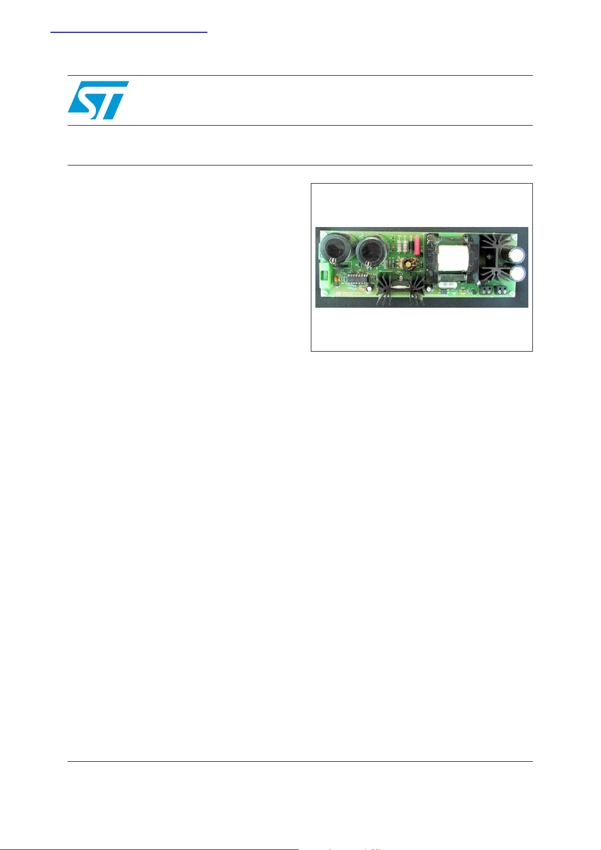
High power 3-phase auxiliary power supply evaluation board
Based on L5991 and ESBT STC08DE150HV
Features
■ 3-phase 150W auxiliary dual output SMPS
■ Input: 400Vac +/- 20%
■ Output voltage 1: 24V, 6.25A @ 90kHz
■ Output voltage 2: 5V, 0.075A @ 90kHz
■ Auxiliary output voltage: 15V, 0.01A
■ Maximum output power : 150W
■ Efficiency > 85%
■ Switching frequency > 90kHz
■ Stand-by switching frequency > 35kHz
■ Feedback: secondary regulation
STEVAL-ISA007V1
Preliminary Data
STEVAL-ISA007V1
Description
Auxiliary SMPS is particularly affected since it is
the entry point for all the biasing of control ICs and
cooling system powering. Standardization
towards "universal input" is reflected in more
stressful conditions for the power transistor used
as the main switch both in terms of blocking
voltage or current capability. Since almost all
auxiliary power supplies are based on fly-back
converters, the need for a blocking voltage as high
as 1500V and over, coupled with high switching
frequency operations, make the ESBTs the
perfect choice for such power supplies. The
STC08DE150HV, in conjunction with the PWM
L5991, perfectly fulfills the requirements and
brings high efficiency to the system
ST components
■ STC08DE150HV Emitter Switched Bipolar
Transistor, 5A, 1500V, TO247-4L HV leads
■ L5991A PWM SMPS controller, DIP-16
■ TL431AI shunt reference, 2.5V, 1mA...100mA,
TO-91
■ PN2222A small signal bipolar transistor, NPN,
40V, 0.6A, 330mW,TO-92
■ STTH102 high voltage ultrafast diode, 200V,
1A, DO-41
■ 1.5KE400A transil, 400V, 1.5kW, DO-201
■ STTH108 high voltage ultrafast diode, 800V,
1A, DO-41
■ STTH3002CT high efficiency ultrafast diode,
200V, 30A, TO-220AC
June 2007 Rev 2 1/5
This is preliminary information on a new product now in development or undergoing evaluation. Details are subject to
change without notice.
www.st.com
5

Reference design general description STEVAL-ISA007V1
1 Reference design general description
A dedicated reference design with ESBT has been developed, featuring the high power wide
input range requirement of a highly demanding industrial market.
The maximum output power is 150W. Generally speaking, the necessity to handle both high
output power and wide input voltage leads to the design of a fly-back stage working in mixed
operation mode: continuous and discontinuous:
The continuous current mode introduces a right half plan zero in the loop-transfer function
which makes the feedback stabilization difficult. At the input voltage range, and after a brief
description of the differences between continuous and discontinuous mode, it will soon be
clear that it is very difficult and inconvenient to design a fly-back converter working in
discontinuous mode. Finally, referring to the power spec of our demo, it is clear that
discontinuous mode cannot be used because it would determine a very high primary and
secondary peak current with a higher cost of all the main components involved: power
transistor, secondary diode and output capacitor.
Thanks to the adoption of the PWM L5991, the converter is able to operate in mixed mode.
For higher power levels with a switching frequency close to 90kHz, the converter operates in
Continuous Current Mode (CCM), while in stand-by and for power levels lower than 25W,
the converter works in Discontinuous Current Mode (DCM) at a switching frequency of
about 35kHz.
2/5

STEVAL-ISA007V1 Board schematic
2 Board schematic
Figure 1. Scheme
3/5

Revision history STEVAL-ISA007V1
3 Revision history
Table 1. Revision history
Date Revision Changes
06-Mar-2006 1 Initial release.
27-Jun-2007 2 ESBT device has been updated
4/5

STEVAL-ISA007V1
Please Read Carefully:
Information in this document is provided solely in connection with ST products. STMicroelectronics NV and its subsidiaries (“ST”) reserve the
right to make changes, corrections, modifications or improvements, to this document, and the products and services described herein at any
time, without notice.
All ST products are sold pursuant to ST’s terms and conditions of sale.
Purchasers are solely responsible for the choice, selection and use of the ST products and services described herein, and ST assumes no
liability whatsoever relating to the choice, selection or use of the ST products and services described herein.
No license, express or implied, by estoppel or otherwise, to any intellectual property rights is granted under this document. If any part of this
document refers to any third party products or services it shall not be deemed a license grant by ST for the use of such third party products
or services, or any intellectual property contained therein or considered as a warranty covering the use in any manner whatsoever of such
third party products or services or any intellectual property contained therein.
UNLESS OTHERWISE SET FORTH IN ST’S TERMS AND CONDITIONS OF SALE ST DISCLAIMS ANY EXPRESS OR IMPLIED
WARRANTY WITH RESPECT TO THE USE AND/OR SALE OF ST PRODUCTS INCLUDING WITHOUT LIMITATION IMPLIED
WARRANTIES OF MERCHANTABILITY, FITNESS FOR A PARTICULAR PURPOSE (AND THEIR EQUIVALENTS UNDER THE LAWS
OF ANY JURISDICTION), OR INFRINGEMENT OF ANY PATENT, COPYRIGHT OR OTHER INTELLECTUAL PROPERTY RIGHT.
UNLESS EXPRESSLY APPROVED IN WRITING BY AN AUTHORIZED ST REPRESENTATIVE, ST PRODUCTS ARE NOT
RECOMMENDED, AUTHORIZED OR WARRANTED FOR USE IN MILITARY, AIR CRAFT, SPACE, LIFE SAVING, OR LIFE SUSTAINING
APPLICATIONS, NOR IN PRODUCTS OR SYSTEMS WHERE FAILURE OR MALFUNCTION MAY RESULT IN PERSONAL INJURY,
DEATH, OR SEVERE PROPERTY OR ENVIRONMENTAL DAMAGE. ST PRODUCTS WHICH ARE NOT SPECIFIED AS "AUTOMOTIVE
GRADE" MAY ONLY BE USED IN AUTOMOTIVE APPLICATIONS AT USER’S OWN RISK.
Resale of ST products with provisions different from the statements and/or technical features set forth in this document shall immediately void
any warranty granted by ST for the ST product or service described herein and shall not create or extend in any manner whatsoever, any
liability of ST.
ST and the ST logo are trademarks or registered trademarks of ST in various countries.
Information in this document supersedes and replaces all information previously supplied.
The ST logo is a registered trademark of STMicroelectronics. All other names are the property of their respective owners.
© 2007 STMicroelectronics - All rights reserved
STMicroelectronics group of companies
Australia - Belgium - Brazil - Canada - China - Czech Republic - Finland - France - Germany - Hong Kong - India - Israel - Italy - Japan -
Malaysia - Malta - Morocco - Singapore - Spain - Sweden - Switzerland - United Kingdom - United States of America
www.st.com
5/5
 Loading...