

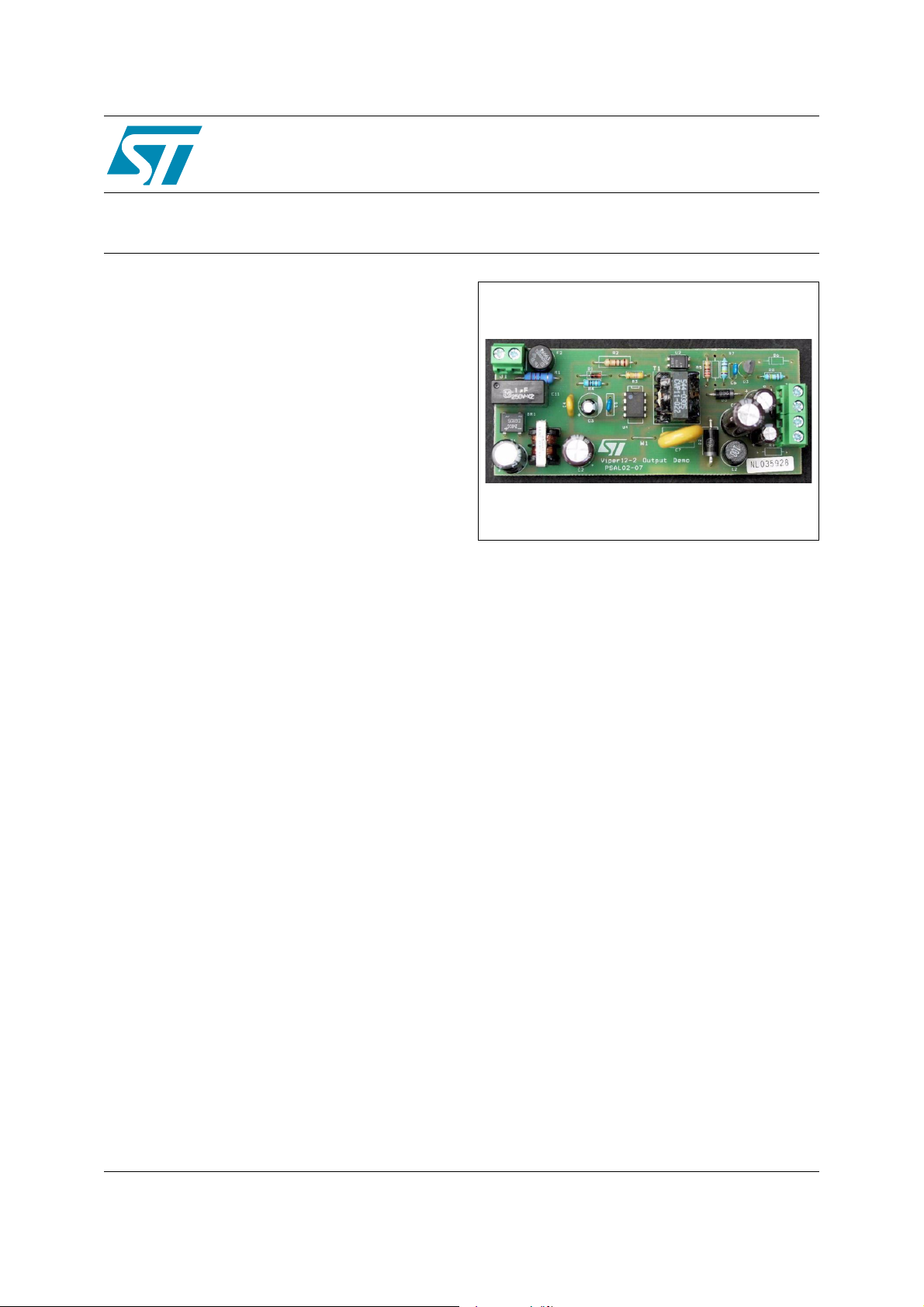
6W Dual Output Supply using VIPer12A
Features
Q Switch mode General Purpose Power Supp ly
Q Input: 85 to 264 VAC @ 50/60 Hz
Q Output: 12V @ 0.5A
Q Output Power (peak) 6W
Q Burst Mode Operation in Standby for Blue
Angel operation
Q Current Mode Control
Q Switching Frequency 60 kHz
Q Over 74% Efficiency
Q Auxiliary Undervoltage Lockout with Hysteresis
Q Output Short Circuit Protection
Q Thermal Shutdown Protec tion
Q Meets EN55022 Class B EMI specification
Applications
This board is an off-line wide range dual output
general-purpose power supply capable of
delivering a total output power
load condition, it operates in the automatic burst
mode while in an overvoltage condition it will
operate in hiccup mode. Other output voltages
can easily be achieved by changing the
transformer and a few components on the board,
as shown in the application note. Transformers
are readily available for the following
configurations:
Q 5V/12V
Q 5V/15V
Q 5V/24V
up t o 6W. In lo w
STEVAL-ISA001V1
Data Brief
STEVAL-ISA001V1
Blue angel
The reference board consumes less than 1W total
power consumption when working in the burst
mode during standby operation and therefore,
meets Blue Angel. Table 2 below outlines the total
power consumption measured on the reference
board at different line voltages with zero load s at
both the outputs. The output voltages remain
regulated when operating in burst mode condition.
Rev 1
February 2006 1/5
For further information contact your local STMicroelectronics sales office
www.st.com
5

General circuit description STEVAL-ISA001V1
1 General circuit description
The circuit operates from 85Vac to 264Vac input voltage with an output power peak of 6W
through two output voltages of 5Vdc and 12Vdc. It contains an input fuse (F2), EMI filtering (C1,
L1, and C2), and the secondary regulation is provided by U2 and U3, the optocoupler and
TL431 respectively. For output filtering, the components used are the output capacitors C8 and
C10. These two output capacitors are sized according to the ripple current and ripple voltage
specifications. The two specifications determine the ESR and RMS current capabilities of the
capacitors used. An additional LC (PI) filter is added to the 5Vdc output, C9-L2 configuration,
for further effective ripple and noise rejection. The AC input is rectified and filtered by the bridge
BR1 and the bulk capacitor C1 to generate the high voltage DC bus applied to the primary
winding of the transformer, T1. The 5Vdc output is sensed with an optocoupler. It is possible to
modify the output voltages by changing the transformer turns ratio and modifying the resistance
values of R7 and R8 in the feedback loop. R2 and C4 form the snubber circuit needed to
reduce the voltage ringing on the drain pin and the leakage spikes.
2/5
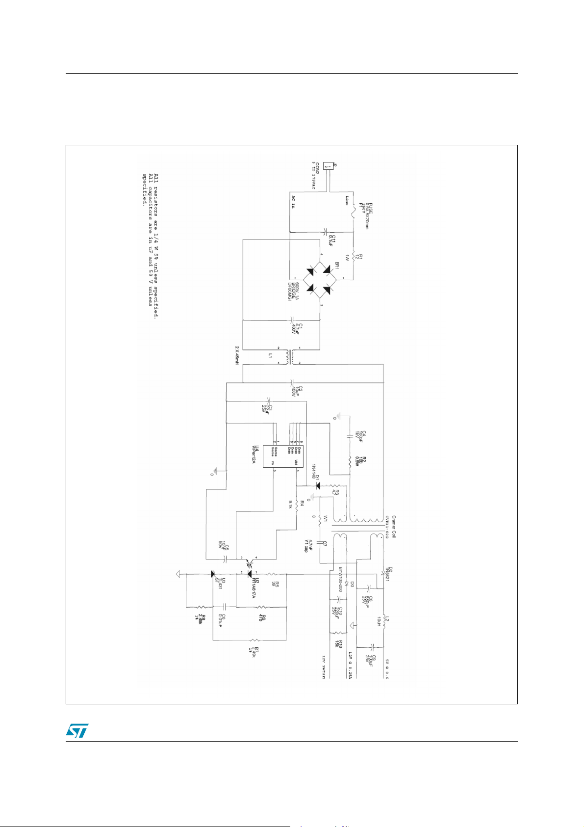
STEVAL-ISA001V1 Boar d Schemat ic
2 Board Schematic
Figure 1. Scheme
3/5

Revision histo ry STEVAL-ISA001V1
3 Revision history
Date Revision Changes
01-Feb-2006 1 Initial release.
4/5

STEVAL-ISA001V1
Information furnished is believed to be accurate and reliable. However, STMicroelectronics assumes no responsibility for the consequences
of use of such information nor for any infringement of patents or other rights of third parties which may result from its use. No license is granted
by implic ation or otherwise under any patent or patent ri ghts of STM i croelectr onics. Sp ecifications menti oned in thi s publicati on are subject
to change without notice. This publication supersedes and replaces all information previously supplied. STMicroelectronics products are not
authoriz ed for use as cri t ic al componen ts in life sup port devices or systems wi thout express written approval of STMi croelectronics.
The ST logo is a registered t rademark of ST M i croelectr oni cs.
All other nam es are the pro perty of thei r respectiv e owners
© 2006 STM icroelectronics - All ri ghts reserved
STMicroelectron ic s group of companies
Austra l i a - Be l gi um - Brazil - Canada - Chi na - Czech Rep ubl i c - Finlan d - France - Germ any - Hong Kong - India - Isr ael - Italy - Japan -
Malaysi a - M al ta - Morocco - Singapore - Spain - Sweden - Swit zerland - Un i ted Kingdom - Uni ted States of America
www.st.com
5/5
 Loading...