

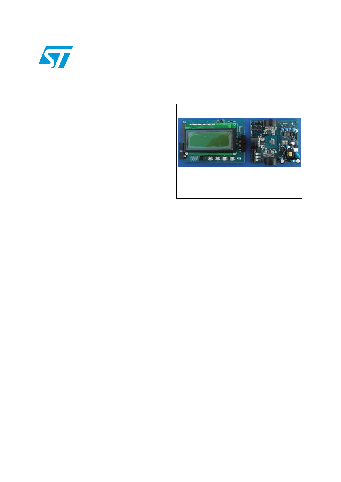
Energy meter (3-phase) demonstration board
based on the STPM01 and STR715FR0
Features
■ 3-phase meters
■ Multi-chip topology, in which each phase is
monitored using a single-phase device
■ Common clock network
■ Power supply in fly-back topology using a
VIPer12ADIP-E
STEVAL-IPE008V1
Data Brief
Description
The STEVAL-IPE008V1 demonstration board
shows how to design a 3-phase meter using
STPM01 as measuring device and a
VIPer12ADIP-E as SMPS (switch mode power
supply). The STPM01 is a metering ASSP
implemented in an advanced 0.35 µm BCD6
technology. It is designed for the effective
measurement of active, reactive, apparent
energies, V
current, and frequency in power line systems that
use the current transformer, Rogowski coil and/or
shunt principle. This device can be used as a
standalone on-board metering device in singlephase energy meter applications or as a
peripheral in a microprocessor based single- or 3phase meter. In a standalone configuration
STPM01 outputs a pulse train signal having a
frequency proportional to the active power used,
while in peripheral mode STPM01 is used in a
microprocessor based application. In this case,
measured data are read at a fixed interval from
the device internal registers by means of SPI
interface processed by a microcontroller.
RMS
, I
, instantaneous voltage and
RMS
STEVAL-IPE008v1
AM03203v1
November 2008 Rev 1 1/8
For further information contact your local STMicroelectronics sales office.
www.st.com
8
Circuit schematics STEVAL-IPE008V1
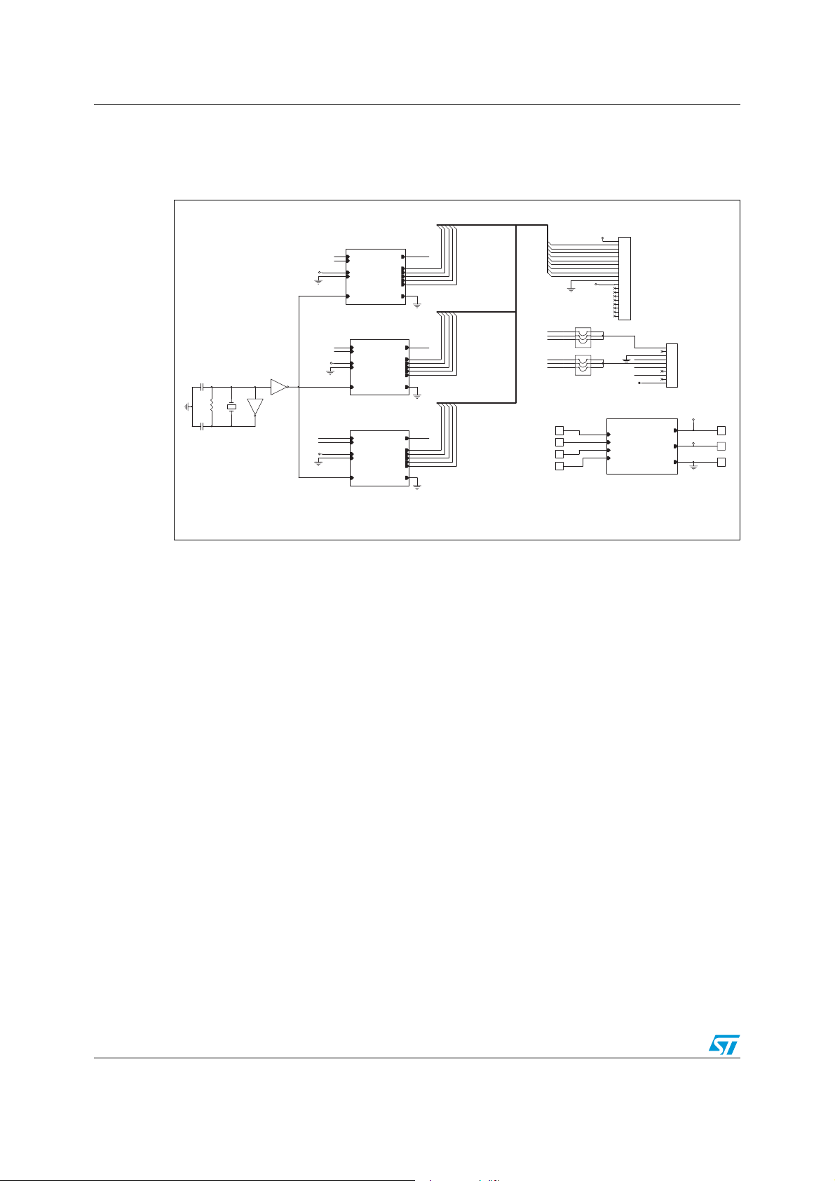
1 Circuit schematics
Figure 1. Top layer circuit schematic
5V
J2
PHASE_1
P1
P
N
N
VDD
VDD
GND
CLKIN
CLKIN CLKOU T
PHASE
PHASE_2
P
N
N
VDD
VDD
P3
N
GND
CLKIN CLKOU T
PHASE
PHASE_3
P
N
VDD
GND
CLKIN CLKOU T
PHASE
U8A
C1
4.194304MHz
15pF
R1
1M
C2
15pF
74HC14A/SO
1 2
3
U8B
Y1
74HC14A/SO
4
VDD
VOTPL1
VOTP
SDA
SDA
SCSL1
SCS
SCL
SCL
LEDL1
LED
SYN
SYN
2LPTOV2P
VOTP
SDA
SDA
SCSL2
SCS
SCL
SCL
LEDL2
LED
SYN
SYN
VOTPL3
VOTP
SDA
SDA
SCSL3
SCS
SCL
SCL
LEDL3
LED
SYN
SYN
SCL
SDA
SYN
SCSL1
SCSL2
SCSL3
LEDL1
LEDL2
LEDL3
J14
1 2
VOTPL1
3 4
VOTPL2
5 6
VOTPL3
JUMPER3
J13
1 2
SCSL1
3 4
SCSL2
5 6
SCSL3
SCSJUMPER
J7 1 J111
J8 1
J9 1
J10 1
1
2
3
4
5
6
7
8
9
10
11
VDD
12
13
14
15
16
17
18
19
20
CON20
J1
VOTP
1
2
3
SDA
4
SCS
5
SCL
6
7
SYN
8
9
VDD
10
SMPS
P1
P1
P2
P2
P3
P3
N
N
SMPS
5V
5V
VDD
3.3V
GND
J121
J51
AM03204v1
2/8
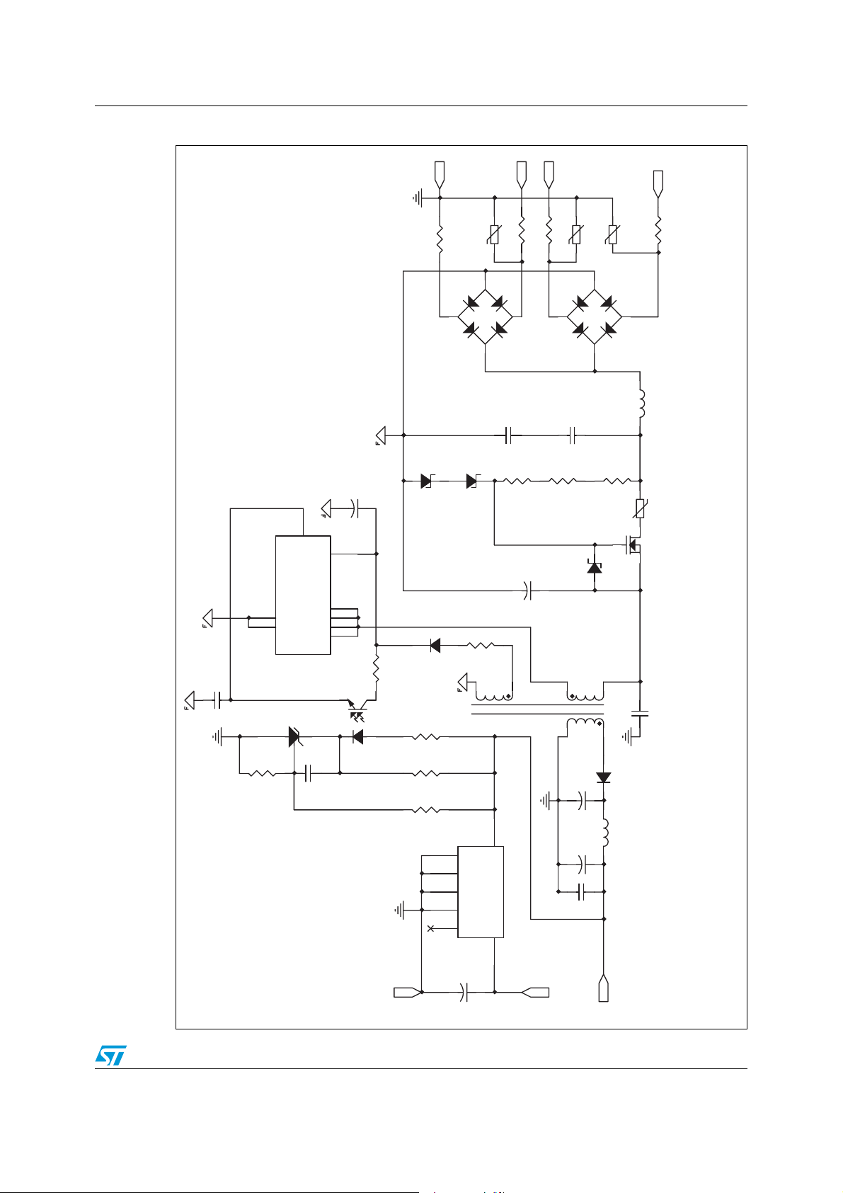
STEVAL-IPE008V1 Circuit schematics
Figure 2. SMPS circuit schematic
N
RV3
R64 22E 1W
SO5K275/275V
1
BRIDGE
C21
10uF 50V
3
FB
Vdd
+
4
D9
180V
D7
180V
3
P2
P
3 22E 1W
R6
R62 22E 1W
4
1
2
-+
3
C19
220nF 630V
330k
BRIDGE
D8
C16
220nF 630V
R60
R59
330k
P1
RV2
RV1
SO5K275/275V
SO5K275/275V
4
2
-+
3
R58
330k
120E
1
D4
R61 22E 1W
D3
1mH
L2
NTC1
4
3
47nF 50V SMD
U5
5
2
1
C24
3
R25
SMD
4.7K 1%
D
S
S
6
D
7
D
8
D
VIPer12AS/ SO-8
R24
5.6K
4
3
PC817
1
U4
2
TS2431
C23
100nF 50V SMD
1
2
GND
LL4148
U3
220E SMD
R21
R22
1K SMD
4.7K 1% SMD
R20
10E SMD
D10
5
R23
2
GND
1000uF 50V
GND
GND
GND
INHIB
C20
+
VIN
VOUT
3
6
7
5
+
4
8
31ABD33
U2 L49
1
3.3V@100mA
ZMM 15/SOD-80
C18 2. 2uF45 0V
1
2
6
10
330uF 25V
C14
+
C15
22uF 16V
+
C17
100nF SMD
3.3V
T1
D5
TMB AT49
3
L
10uH 12 5mA SMD
5V@10mA
5V
Q1 STD5nk40Z
C22
2nF/2kV (Y1)
AM03205v1
3/8

Circuit schematics STEVAL-IPE008V1
Figure 3. Phase circuit schematic
SCS
LED
SCL
VOTP
GND
SDA
CLKI N
VDD
SYN
CLKO UT
GND
LED
VOTP
SDA
LED
R2 750
12
D1
VDD
SCL
SYN
SCS
R7
13
11
16
19
18
Scl
Sda
U1
led
MON
124
20
C8
1MY
C7
1nF
C6
1nF
D2
C5
1MY
C4
1nF
C3
1nF
12
17153
14
Vin
Vip
Iln2
Syn
Scs
CLKi n
CLKo ut
MOP
Vcc
Vddd
Vss
5
6
LL4148
STPM0 1_TSSOP20
Vdda
Iln1 Ilp2
Votp
Ilp1
9
8
7
10
C9
10nF
VDD
R5 1k
R6
3.4
CT
L1
1
VOTP
R10
150K
R9
2,2K
C12
C11
0
R13
2.2M
4
2
R8 1k
N
N
33nF
4.7u
R17 470
R16
200K
R15
270K
R14
270K
P
P
3
AM03206v1
4/8

STEVAL-IPE008V1 Circuit schematics
Figure 4. Clock management network schematic
PHASE_1
SDA
SCS
SCL
LED
SYN
VOTP
SDA
SCS
SCL
LED
SYN
VOTPL1
SDA
SCSL1
SCL
LEDL1
SYN
SDA
SCSL2
SCL
LEDL2
SYN
2LPTOV2P
C1
15pF
4.194304MHz
R1
1M
P1
P
N
N
VDD
CLKI N
VDD
U8A
74HC14A/SO
1 2
34
Y1
U8B
74HC14A/SO
VDD
GND
CLKI N CLKO UT
PHASE
PHASE_2
N
P
N
VDD
GND
CLKI N CLK OU T
PHASE
VOTP
C2
15pF
VDD
PHASE_3
P3
N
P
N
VDD
GND
CLKI N CLK OU T
PHASE
VOTP
SDA
SCS
SYN
SCL
LED
VOTPL3
SDA
SCSL3
SCL
LEDL3
SYN
AM03207v1
5/8

Circuit schematics STEVAL-IPE008V1
Figure 5. Connectors schematic
VOTPL1
VOTPL2
VOTPL3
SCSL1
SCSL2
SCSL3
SCL
SDA
SYN
SCSL1
SCSL2
SCSL3
LEDL1
LEDL2
LEDL3
J14
1 2
3 4
5 6
JUMPER3
J13
1 2
3 4
5 6
SCSJUM PER
VDD
5V
J2
1
2
3
4
5
6
7
8
9
10
11
12
13
14
15
16
17
18
19
20
CON2 0
VDD
VOTP
SDA
SCS
SCL
SYN
J1
1
2
3
4
5
6
7
8
9
10
6/8
AM03208v1

STEVAL-IPE008V1 Revision history
2 Revision history
Table 1. Document revision history
Date Revision Changes
25-Nov-2008 1 Initial release.
7/8

STEVAL-IPE008V1
Please Read Carefully:
Information in this document is provided solely in connection with ST products. STMicroelectronics NV and its subsidiaries (“ST”) reserve the
right to make changes, corrections, modifications or improvements, to this document, and the products and services described herein at any
time, without notice.
All ST products are sold pursuant to ST’s terms and conditions of sale.
Purchasers are solely responsible for the choice, selection and use of the ST products and services described herein, and ST assumes no
liability whatsoever relating to the choice, selection or use of the ST products and services described herein.
No license, express or implied, by estoppel or otherwise, to any intellectual property rights is granted under this document. If any part of this
document refers to any third party products or services it shall not be deemed a license grant by ST for the use of such third party products
or services, or any intellectual property contained therein or considered as a warranty covering the use in any manner whatsoever of such
third party products or services or any intellectual property contained therein.
UNLESS OTHERWISE SET FORTH IN ST’S TERMS AND CONDITIONS OF SALE ST DISCLAIMS ANY EXPRESS OR IMPLIED
WARRANTY WITH RESPECT TO THE USE AND/OR SALE OF ST PRODUCTS INCLUDING WITHOUT LIMITATION IMPLIED
WARRANTIES OF MERCHANTABILITY, FITNESS FOR A PARTICULAR PURPOSE (AND THEIR EQUIVALENTS UNDER THE LAWS
OF ANY JURISDICTION), OR INFRINGEMENT OF ANY PATENT, COPYRIGHT OR OTHER INTELLECTUAL PROPERTY RIGHT.
UNLESS EXPRESSLY APPROVED IN WRITING BY AN AUTHORIZED ST REPRESENTATIVE, ST PRODUCTS ARE NOT
RECOMMENDED, AUTHORIZED OR WARRANTED FOR USE IN MILITARY, AIR CRAFT, SPACE, LIFE SAVING, OR LIFE SUSTAINING
APPLICATIONS, NOR IN PRODUCTS OR SYSTEMS WHERE FAILURE OR MALFUNCTION MAY RESULT IN PERSONAL INJURY,
DEATH, OR SEVERE PROPERTY OR ENVIRONMENTAL DAMAGE. ST PRODUCTS WHICH ARE NOT SPECIFIED AS "AUTOMOTIVE
GRADE" MAY ONLY BE USED IN AUTOMOTIVE APPLICATIONS AT USER’S OWN RISK.
Resale of ST products with provisions different from the statements and/or technical features set forth in this document shall immediately void
any warranty granted by ST for the ST product or service described herein and shall not create or extend in any manner whatsoever, any
liability of ST.
ST and the ST logo are trademarks or registered trademarks of ST in various countries.
Information in this document supersedes and replaces all information previously supplied.
The ST logo is a registered trademark of STMicroelectronics. All other names are the property of their respective owners.
© 2008 STMicroelectronics - All rights reserved
STMicroelectronics group of companies
Australia - Belgium - Brazil - Canada - China - Czech Republic - Finland - France - Germany - Hong Kong - India - Israel - Italy - Japan -
Malaysia - Malta - Morocco - Singapore - Spain - Sweden - Switzerland - United Kingdom - United States of America
www.st.com
8/8
 Loading...