

Offline constant current LED driver based on the VIPer17
Features
■ Input voltage 220 VAC +/- 20%
■ 800 V avalanche rugged power section
■ Provides 500 mA constant current for LED
■ High precision constant current with +/- 5%
tolerance (1 sense resistor and 2 resistor
bridges with +/- 1% precision)
■ Overtemperature protection
■ LED open-circuit protection
■ LED short-circuit protection
■ PWM operation with frequency jittering for low
EMI
■ Operating frequency:
– 60 kHz for L type
– 115 kHz for H type
■ Standby power < 50 mW at 265 VAC
■ Adjustable and accurate overvoltage
protection
■ On-board soft-start
■ Safe auto-restart after a fault condition
Applications
■ Adapters for PDAs, camcorders, electric
shavers, cellular phones, videogames
■ Auxiliary power supply for LCD/PDP TVs,
monitors, audio systems, computers, industrial
applications
■ SMPS for set-top boxes, DVD players/
recorders, white goods
STEVAL-ILL017V1
Data Brief
STEVAL-ILL017V1
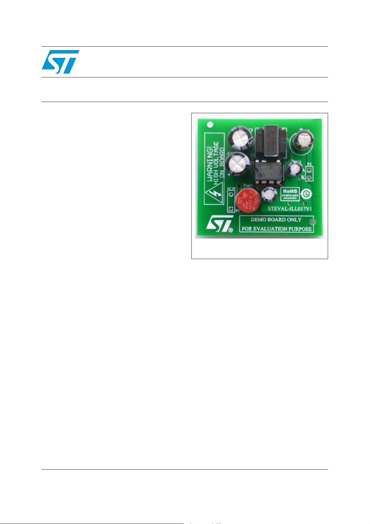
VDC source, suitable for illuminating two LEDs in
series.
The VIPer17 device is an offline converter with an
800 V rugged power section, a PWM control,
overcurrent protection, overvoltage and overload
protection, hysteretic thermal protection, soft-start
and safe auto-restart after the removal of a fault
condition. The brown-out protection function is
embedded into the high voltage start-up.
Burst mode operation and the very low
consumption of the device combine to meet
standby energy saving regulations. Advanced
frequency jittering reduces EMI filter cost.
Description
The STEVAL-ILL017V1 demonstration board is a
2 W non-isolated offline constant current LED
driver based on the VIPer17. The board operates
with an input ranging from 176 V to 264 VAC and
provides 500 mA of constant current from a 7
September 2008 Rev 1 1/4
For further information contact your local STMicroelectronics sales office.
www.st.com
4

Circuit schematic STEVAL-ILL017V1
e1
use
250V
2.2u
nsfor
ST
S2H100
220u
1.2
STTH1R06
10u
GN
GN
GN
240
1n
100
82
12n
Vcc
Out1
Nonin
cc
Nonin
Out2
TSM103W
56n
10
100n
R1
24
R1
3.3
C1
470p
10
100n
AC
ED
Ou
BAT4
C1
10u
6.8
C1
1u
R1
1.2
R1
2.7
Drai
Drai
Sourc
Con
Vd
ER1
2.2n
56
R1
BC817
40
dg
C1
2.2u
VNe
us
rain
1 Circuit schematic
Figure 1. Schematic diagram
t
Ou
1
2
P2
LED
1
K
24
v2Inv2Out2
Nonin
F
100n
R1
U2
v1
-
TSM103W
3
Vcc
2
Inv1 Nonin
+
Out1
Vcc
K
R2
6.8
8 4
F
C8
100n
K
R5
10
K
R3
100
4
1M
-40
Q1
BC817
K
3
F
C4
R1
2.7
56n
F
C6
2.2n
F
C1
1n
F
2
C1
10u
K R1
R4
56
2
1.2
12
1.2
R1
D
GN
A
STTH1R06
C5
5
6
7
8
U1
D3
D
GN
F
10u
7
VIPER1
R1
0
F
C1
470p
K
0
3.3
R1
R8
3K
5
6
K
R7
82
71
F
12n
C7
5
R6
10
D
GN
e
BRDrai
nDrai
n
1
Sourc
4
FB
t
d
Con
Vd
3
2
K
240
C2
R9
F
C9
220u
3
F
1u
C1
A
D6
PS2H100
ST
8
mer
T1
Transfor
3
7
1
6
D5
Drain
F
C3
2.2u
F
L2
1mH
u
VNe
3
e VPOS VP
VL_Fus
250V
Fuse1
Fuse
VL ine
1
C1
D1
2.2u
e
Bridg
6
BAT4
2
4
1
1
2
In
P1
AC
2/4
STEVAL-ILL017V1 Revision history
2 Revision history
Table 1. Document revision history
Date Revision Changes
01-Sep-2008 1 Initial release.
3/4

STEVAL-ILL017V1
y
Please Read Carefully:
Information in this document is provided solely in connection with ST products. STMicroelectronics NV and its subsidiaries (“ST”) reserve the
right to make changes, corrections, modifications or improvements, to this document, and the products and services described herein at any
time, without notice.
All ST products are sold pursuant to ST’s terms and conditions of sale.
Purchasers are solely responsible for the choice, selection and use of the ST products and services described herein, and ST assumes no
liability whatsoever relating to the choice, selection or use of the ST products and services described herein.
No license, express or implied, by estoppel or otherwise, to any intellectual property rights is granted under this document. If any part of this
document refers to any third party products or services it shall not be deemed a license grant by ST for the use of such third party products
or services, or any intellectual property contained therein or considered as a warranty covering the use in any manner whatsoever of such
third party products or services or any intellectual property contained therein.
UNLESS OTHERWISE SET FORTH IN ST’S TERMS AND CONDITIONS OF SALE ST DISCLAIMS ANY EXPRESS OR IMPLIED
WARRANTY WITH RESPECT TO THE USE AND/OR SALE OF ST PRODUCTS INCLUDING WITHOUT LIMITATION IMPLIED
WARRANTIES OF MERCHANTABILITY, FITNESS FOR A PARTICULAR PURPOSE (AND THEIR EQUIVALENTS UNDER THE LAWS
OF ANY JURISDICTION), OR INFRINGEMENT OF ANY PATENT, COPYRIGHT OR OTHER INTELLECTUAL PROPERTY RIGHT.
UNLESS EXPRESSLY APPROVED IN WRITING BY AN AUTHORIZED ST REPRESENTATIVE, ST PRODUCTS ARE NOT
RECOMMENDED, AUTHORIZED OR WARRANTED FOR USE IN MILITARY, AIR CRAFT, SPACE, LIFE SAVING, OR LIFE SUSTAINING
APPLICATIONS, NOR IN PRODUCTS OR SYSTEMS WHERE FAILURE OR MALFUNCTION MAY RESULT IN PERSONAL INJURY,
DEATH, OR SEVERE PROPERTY OR ENVIRONMENTAL DAMAGE. ST PRODUCTS WHICH ARE NOT SPECIFIED AS "AUTOMOTIVE
GRADE" MAY ONLY BE USED IN AUTOMOTIVE APPLICATIONS AT USER’S OWN RISK.
Resale of ST products with provisions different from the statements and/or technical features set forth in this document shall immediately void
any warranty granted by ST for the ST product or service described herein and shall not create or extend in any manner whatsoever, an
liability of ST.
ST and the ST logo are trademarks or registered trademarks of ST in various countries.
Information in this document supersedes and replaces all information previously supplied.
The ST logo is a registered trademark of STMicroelectronics. All other names are the property of their respective owners.
© 2008 STMicroelectronics - All rights reserved
STMicroelectronics group of companies
Australia - Belgium - Brazil - Canada - China - Czech Republic - Finland - France - Germany - Hong Kong - India - Israel - Italy - Japan -
Malaysia - Malta - Morocco - Singapore - Spain - Sweden - Switzerland - United Kingdom - United States of America
www.st.com
4/4
 Loading...