

Page 1
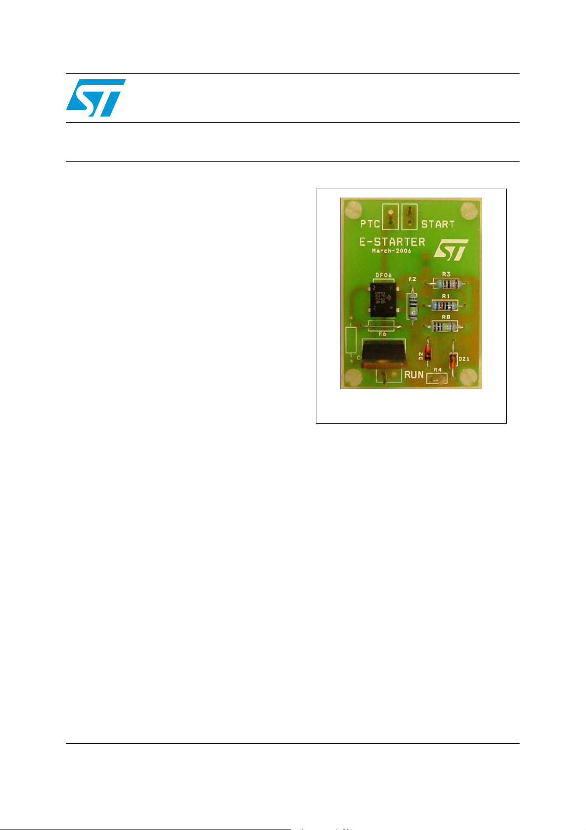
Low-loss e-STARTER demonstration board for compressor
Features
■ Suitable for refrigerator and freezer
compressor applications
■ Reduces PTC resistor power losses
Description
The e-STARTER demonstration board represents
an innovative solution patented by
STMicroelectronics to reduce the power losses
caused by positive temperature coefficient (PTC)
resistors in compressor starter circuits.
The solution features an ACST6 AC switch device
which is used to turn off the PTC current after
motor start-up. It should be noted that the
traditional PTC is still used in the electronic
starter circuit, as it increases the safety of the
circuit in cases of AC switch short-circuit or diode
mode failure (ref. EN60335-1).
STEVAL-IHT003V1
starter circuits based on the ACST6
Data Brief
STEVAL-IHT003V1
The design allows the starter standby losses to be
reduced from (typ) 2.5 W to 380 mW for 230 V
applications, or 2.5 W to 40 mW for 100 V
applications.
Because this board is not a “plug and play”
solution, prior to using the board with a
compressor the PTC behavior must be checked
(especially VPTC1 & VPTC2 levels), and different
R4 resistor value may be required.
July 2008 Rev 1 1/4
For further information contact your local STMicroelectronics sales office.
www.st.com
4
Page 2

Schematic diagram STEVAL-IHT003V1
1 Schematic diagram
Figure 1. e-STARTER circuit schematic
C1
10 nF
BZX55C
A
1 MΩ
V
C2
V
AM00202
D1
1N4007
R3
R4
30 kΩ
510 kΩ
R5
Q1
PMBT2907A
D2
C1
10 kΩ
DZ1
C
Q2
R8
1N4148PMBT2222A
R7
C2
10 nF
(1)
C3
x nF
GND
220 Ω
1
3
0
R2
470 kΩ
R1
620 Ω
1
D7
+
4
1
3
DF06
2
R6
1
3
MMBF170
M1
T2
X0205N
3
–
22 nF
C4
47 Ω
A
I
ACST6
T1
AK
V
J16
START
J17
1. Capacitor C3 is not soldered on the board, but can be added in order to evaluate its impact on board
immunity.
2/4
PTC
J18
RUN
Page 3

STEVAL-IHT003V1 Revision history
2 Revision history
Table 1. Document revision history
Date Revision Changes
08-Jul-2008 1 Initial release.
3/4
Page 4

STEVAL-IHT003V1
Please Read Carefully:
Information in this document is provided solely in connection with ST products. STMicroelectronics NV and its subsidiaries (“ST”) reserve the
right to make changes, corrections, modifications or improvements, to this document, and the products and services described herein at any
time, without notice.
All ST products are sold pursuant to ST’s terms and conditions of sale.
Purchasers are solely responsible for the choice, selection and use of the ST products and services described herein, and ST assumes no
liability whatsoever relating to the choice, selection or use of the ST products and services described herein.
No license, express or implied, by estoppel or otherwise, to any intellectual property rights is granted under this document. If any part of this
document refers to any third party products or services it shall not be deemed a license grant by ST for the use of such third party products
or services, or any intellectual property contained therein or considered as a warranty covering the use in any manner whatsoever of such
third party products or services or any intellectual property contained therein.
UNLESS OTHERWISE SET FORTH IN ST’S TERMS AND CONDITIONS OF SALE ST DISCLAIMS ANY EXPRESS OR IMPLIED
WARRANTY WITH RESPECT TO THE USE AND/OR SALE OF ST PRODUCTS INCLUDING WITHOUT LIMITATION IMPLIED
WARRANTIES OF MERCHANTABILITY, FITNESS FOR A PARTICULAR PURPOSE (AND THEIR EQUIVALENTS UNDER THE LAWS
OF ANY JURISDICTION), OR INFRINGEMENT OF ANY PATENT, COPYRIGHT OR OTHER INTELLECTUAL PROPERTY RIGHT.
UNLESS EXPRESSLY APPROVED IN WRITING BY AN AUTHORIZED ST REPRESENTATIVE, ST PRODUCTS ARE NOT
RECOMMENDED, AUTHORIZED OR WARRANTED FOR USE IN MILITARY, AIR CRAFT, SPACE, LIFE SAVING, OR LIFE SUSTAINING
APPLICATIONS, NOR IN PRODUCTS OR SYSTEMS WHERE FAILURE OR MALFUNCTION MAY RESULT IN PERSONAL INJURY,
DEATH, OR SEVERE PROPERTY OR ENVIRONMENTAL DAMAGE. ST PRODUCTS WHICH ARE NOT SPECIFIED AS "AUTOMOTIVE
GRADE" MAY ONLY BE USED IN AUTOMOTIVE APPLICATIONS AT USER’S OWN RISK.
Resale of ST products with provisions different from the statements and/or technical features set forth in this document shall immediately void
any warranty granted by ST for the ST product or service described herein and shall not create or extend in any manner whatsoever, any
liability of ST.
ST and the ST logo are trademarks or registered trademarks of ST in various countries.
Information in this document supersedes and replaces all information previously supplied.
The ST logo is a registered trademark of STMicroelectronics. All other names are the property of their respective owners.
© 2008 STMicroelectronics - All rights reserved
STMicroelectronics group of companies
Australia - Belgium - Brazil - Canada - China - Czech Republic - Finland - France - Germany - Hong Kong - India - Israel - Italy - Japan -
Malaysia - Malta - Morocco - Singapore - Spain - Sweden - Switzerland - United Kingdom - United States of America
www.st.com
4/4
 Loading...