

STEVAL-IHP002V2
STEVAL-IHP002V2
Smartplug system to measure and control AC loads based on the
STM32, ST7540 PLM and STPM01
Data brief
Features
■ Energy measurement by the STPM01
■ Power line communication by the ST7540 up to
4.8 kbps
■ USART connectivity or expansion connector
■ Output with two contacts (NO/NC) and
common contact for generic load
■ Designed to fit a standard "503" wall box
■ RoHS compliant
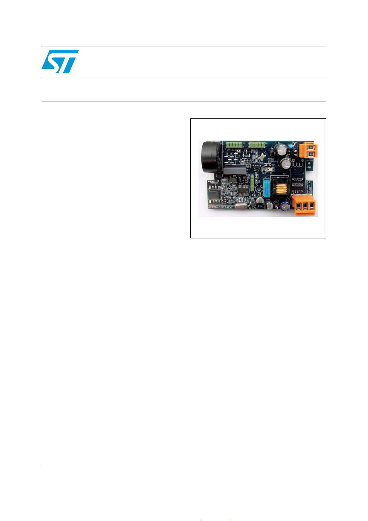
Description
The STEVAL-IHP002V2 demonstration board
implements a PLM smartplug node which allows
monitoring the energy consumption of a mains
plug and controlling any kind of load in on/off
mode through a relay.
The board is based on the STM32F103CB
microcontroller, the ST7540 PLM module and the
STPM01 mono-phase energy metering IC.
The board is designed to fit a standard "503" wall
box.
The voltage, current, power, active energy and the
output status can be sent to a PLM data
concentrator through a power line communication
network on request. Moreover, if the power
consumption changes, it is sent asynchronously
to the data concentrator.
March 2012 Doc ID 022253 Rev 1 1/10
For further information contact your local STMicroelectronics sales office.
www.st.com
10
Circuits schematic STEVAL-IHP002V2
!-V
%!24(
'.$?0,-
-#5
34-
0,-?48
0,-?3#+
0,-?2X4X
:#2
0,-?28
340-?-)3/
340-?-/3)
-#/
/04?#-$
340-?3#3
0,-?#$0$
53!24?48
340-?39.
53!24?28
340-?3#+
0,-?"5
0,-?2%'$!4 !
$IMMER3WITCH
42)!#2ELAY
/04?/54?#-$
26
6!
26
26
6!
26
0OWER3UPPLY
!LTAIR
,
.
&!&
!
%NERGY-EASUREMENT
340-
:#2
30)?3#3
30)?#,+
,
.
39.?-#5
30)?-)3/
#,+
0,-
34
#$0$
2%'?$!4 !
2X4X
,
#,24
.
2X$
"54(%2-
4X$
*
#/.
*
#/.
0##OMM
23
5!24? 48
5!24? 28
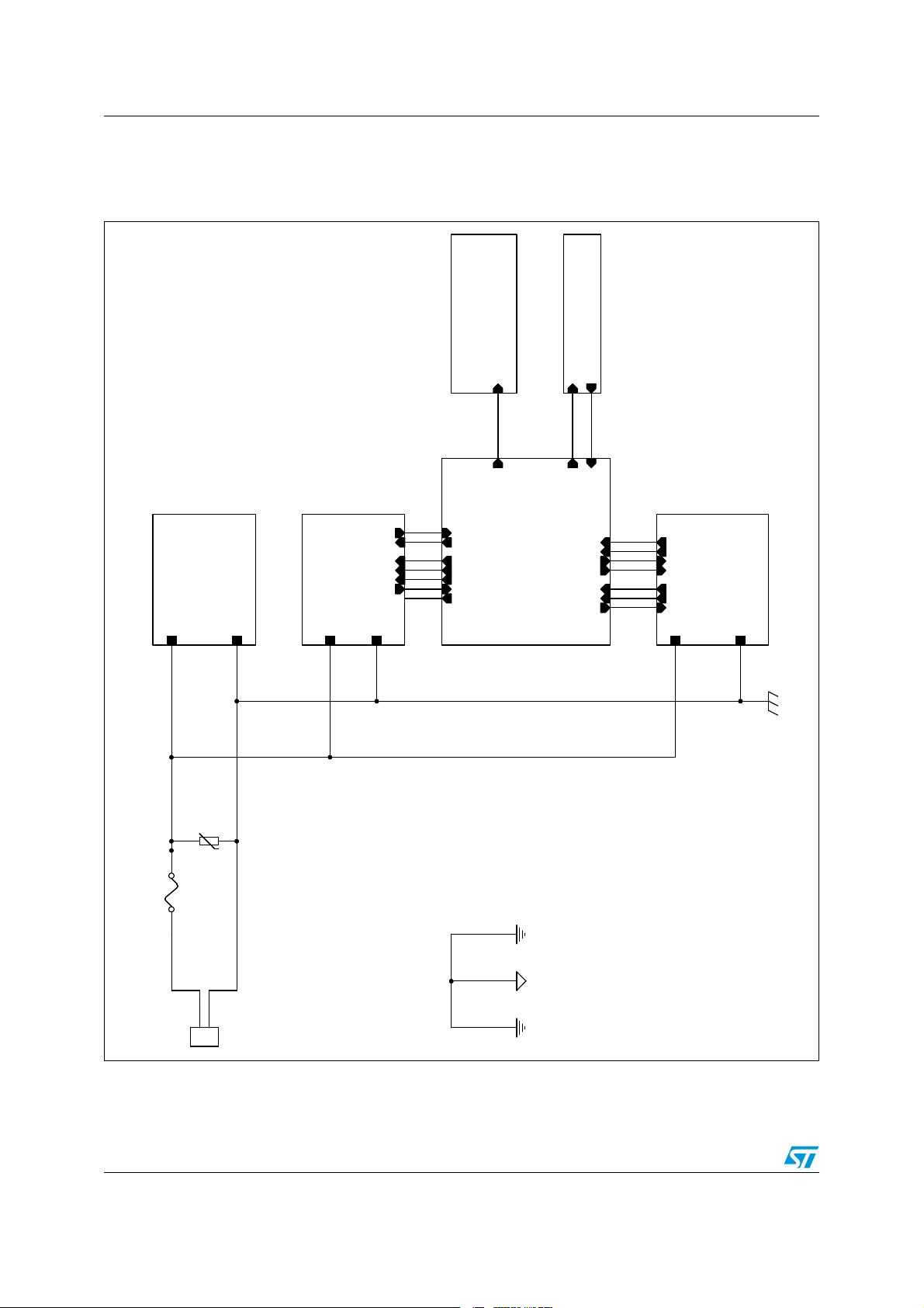
1 Circuits schematic
Figure 1. Top-level schematic
2/10 Doc ID 022253 Rev 1
STEVAL-IHP002V2 Circuits schematic
AM10555v1
L
N
VCC_3V3
VCC_12V
R611kR61
1k
+
C117
4.7uF 400V
+
C117
4.7uF 400V
R110
22 1W
R110
22 1W
D17
LL4148
D17
LL4148
+
C120
2.2uF+C120
2.2uF
R112
10k
R112
10k
C118
470pF 400V
C118
470pF 400V
1
2
R111
120K
R111
120K
C124
1nF
C124
1nF
1
2
DL1
RED
DL1
RED
C122
470nF
C122
470nF
1
2
T2T2
1
3
5
2
4
8
R11310R113
10
+
C96
47uF 25V
+
C96
47uF 25V
+
C116
4.7uF 400V
+
C116
4.7uF 400V
L9
10uHL910uH
1 2
R118
10K
R118
10K
-
+
D14
BRMB6S-RC
-
+
D14
BRMB6S-RC
2
3
1
4
D15
STPS1H100A
D15
STPS1H100A
+
C95
100uF 16V
+
C95
100uF 16V
+
C119
470uF 16V Low ESR
+
C119
470uF 16V Low ESR
R116
2.2
R116
2.2
R11722R117
22
L8
470uHL8470uH
1 2
C121
2.2nF
C121
2.2nF
1
2
C123
10nF
C123
10nF
1
2
R114
27K
R114
27K
D16
STTH1L06A
D16
STTH1L06A
IC3
LD1117ADT33TR
IC3
LD1117ADT33TR
VOUT
2
VIN
3
GND
1
R115
4.7K
R115
4.7K
2.5V
COMP
SOURCE
DRAIN
VDD
+
-
CURRENT
CONTROL
IREF
GND
FB/ZCD
NC
U13
ALTAIR05T-800
2.5V
COMP
SOURCE
DRAIN
VDD
+
-
CURRENT
CONTROL
IREF
GND
FB/ZCD
NC
U13
ALTAIR05T-800
6
7
13
5
4
3
1
14
16
2
15
8
9
10
11
12
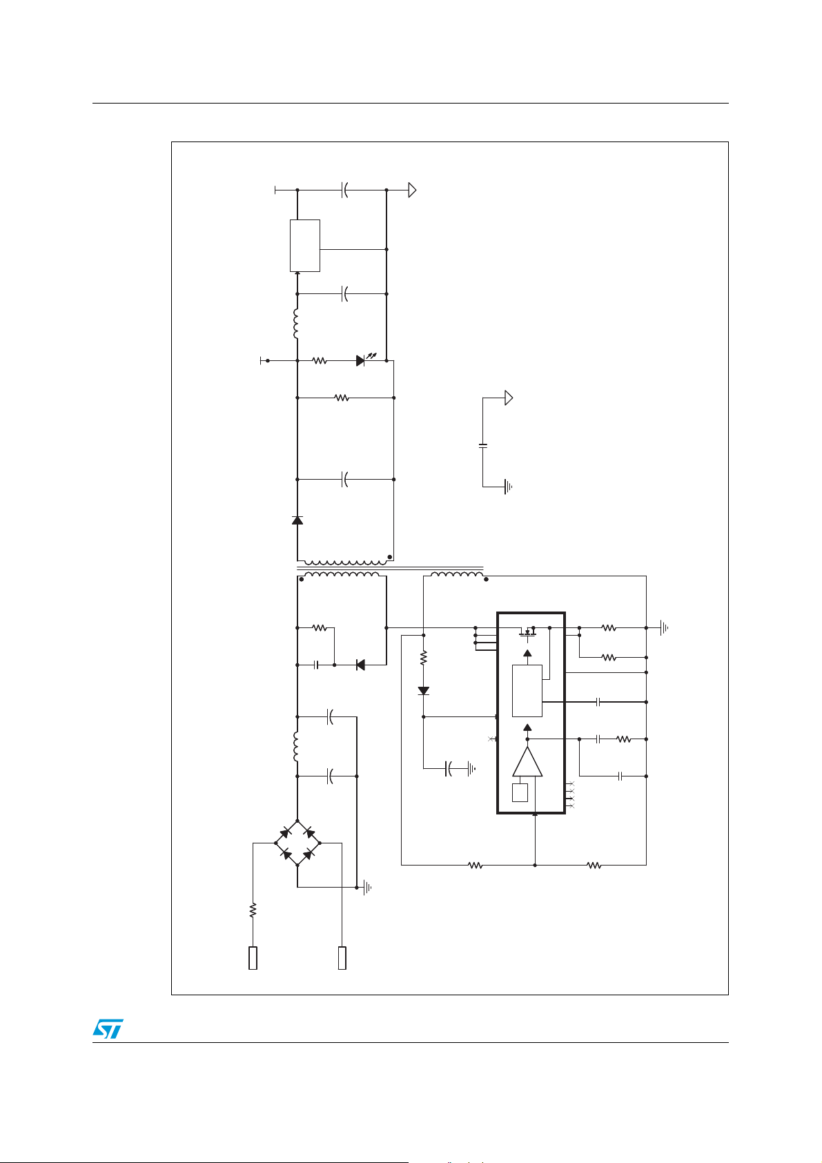
Figure 2. Power supply section
Doc ID 022253 Rev 1 3/10

Circuits schematic STEVAL-IHP002V2
!-V
5!24?48
5!24?28
*
53!24
*
53!24
Figure 3. USART expansion connector section
4/10 Doc ID 022253 Rev 1

STEVAL-IHP002V2 Circuits schematic
AM10557v1
Analog
Signal
Ground
Digital
Ground
Analog
Power
Ground
PA
TEST PADS
OSCIN
Non Isolated topology for 132kHz (Band C)
TEST1
WD
PA_IN-
UART/SPI
MCLK
RSTO
TEST2
CL
Vsense
Tx_OUT
Vsense
Tx_OUT
CL
Rx_IN
TEST1
TEST2
PA_IN+
PA_OUT
Tx_OUT
Vdd
PA_OUT
PA_OUT
PA_IN-
SVss
Rx_IN
PA_IN+
PA_IN+
PA_IN-
Vsense
CD/PD
REG_DATA
CL
Rx_IN
Tx_OUT
CD/PD
REG_DATA
RxD
RxTx
TxD
BU/THERM
CLR/T
L
N
Vcc
Vcc
Vcc
VDC
Vcc
VDC
Vdd
VDC
Vdd
VDC
VDC
VDC
Vdd
Vcc VCC_12V
GND_PLM
Vcc
Vdd
VDC
R13
2k7
R13
2k7
R20
56k
R20
56k
C15
10 uF
C15
10 uF
TP12TP12
TP27TP27
C27
10 nF
C27
10 nF
R121kR12
1k
C33
100 pF
C33
100 pF
C17
10 uF
C17
10 uF
TP11TP11
U3
ST7540U3ST7540
CD/PD
1
REG_DATA
2
GND
3
RxD4Rx/Tx
5
TxD
6
BU/THERM7CLR/T
8
Vdd
9
MCLK
10
RSTO
11
UART/SPI
12
WD
13
PA_IN-
14
PA_OUT
15
Vss
16
Vcc
17
PA_IN+
18
Tx_OUT
19
SVss
20
X1_OSCIN
21
X2
22
Vsense
23
CL
24
Rx_IN
25
VDC
26
TEST1
27
TEST2
28
R7
47KR747K
TP15TP15
C31
22 pF
C31
22 pF
R6
1k1R61k1
R14
1k8
R14
1k8
C32
270 pF
C32
270 pF
C18
100 nF
C18
100 nF
J1
PEAK METER CONNECTORJ1PEAK METER CONNECTOR
123
4
5
D8
BAT54S/SOTD8BAT54S/SOT
3
1
2
X1
16MhzX116Mhz
D10
BAT54S/SOT
D10
BAT54S/SOT
31
2
R9
4k7R94k7
TP16TP16
C24
10 uF
C24
10 uF
R8
15kR815k
JP5
CLOSE
JP5
CLOSE
1 2
L5
22 uHL522 uH
1
2
C30
15 pF
C30
15 pF
L6
220 uHL6220 uH
1
2
TP14TP14
D9
SM6T15CAD9SM6T15CA
C22
10uF
C22
10uF
R10
13k
R10
13k
C23
68nF X2
C23
68nF X2
C16
100 nF
C16
100 nF
TP13TP13
C26
6.8 nF
C26
6.8 nF
C12
33pF
C12
33pF
R17
470
R17
470
C14
10nF
C14
10nF
C25
100 nF
C25
100 nF
C11
33pF
C11
33pF
T3
Line transformerT3Line transformer
1
845
C21
100pF
C21
100pF
R19
2k4
R19
2k4
JP4
CLOSE
JP4
CLOSE
1
2
TP25TP25
TP22TP22
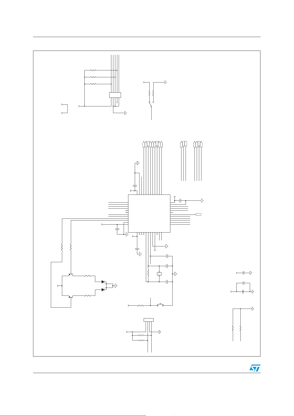
Figure 4. Power line modem section
Doc ID 022253 Rev 1 5/10
Circuits schematic STEVAL-IHP002V2
AM10558v1
BOOT_0
RESET#
JT-NTRST
JT-TDO
JT-TCK
JT-TMS
JT-TDI
SPI2_SCK
SPI2_MISO
SPI2_MOSI
PA4
SPI1_SCK
SPI1_MISO
SPI1_MOSI
BOOT_1
RESET#
RESET#
JT-TMS
JT-TDI
JT-TDO
JT-TCK
USART1_RX
USART1_TX
SPI1_SCK
PA4
SPI1_MOSI
SPI1_MISO
PA1
PA2
PA3
PA3
PA2
PA1
TIM3_CH3
BOOT_0
BOOT_1
I2C2_SCL
I2C2_SDA
I2C2_SDA
I2C2_SCL
CAL
CAL
USART_TX
STPM01_MOSI
STPM01_MISO
STPM01_SCK
PLM_Rx/Tx
MCO
PLM_SCK
PLM_RX
PLM_TX
USART_RX
PLM_BU
PLM_CD/PD
PLM_REG/DATA
ZCR
STPM01_SCS
STPM01_SYN
OPT_CMD
+3.3V
+3.3V
+3.3V
+3.3V
+3.3V
+3.3V
+3.3V
+3.3V
+3.3V
+3.3V
VCC_3V3
+3.3V
+3.3V
+3.3V
C98
100nF
C98
100nF
R78
10k
R78
10k
R6982R69
82
R77
10k
R77
10k
6TBC301F2
3
MTS11U 6TBC301F23MTS11U
PA0-WKUP
10
PA1
11
PA2
12
PA3
13
PA4
14
PA5
15
PA6
16
PA7
17
PA829PA9
30
PA1031PA11
32
PA12
33
PA13
34
PA14
37
PA15
38
PB0
18
PB1
19
PB2
20
PB3
39
PB10
21
PB11
22
PB12
25
PB13
26
PB14
27
PB15
28
PB4
40
PB5
41
PB6
42
PB7
43
PB8
45
PB9
46
PC143PC15
4
PD0/OSC-IN
5
PD1/OSC-OUT
6
NRST
7
BOOT0
44
VBAT
1
VSSA
8
VSS1
23
VSS2
35
VSS3
47
VDDA
9
VDD1
24
VDD2
36
VDD3
48
PC13/TAMP/RTC
2
C6
22pFC622pF
R72
4.7K
R72
4.7K
R109
4.7k
R109
4.7k
D1
BI-COLOR LED RED/GREEND1BI-COLOR LED RED/GREEN
C104
100nF
C104
100nF
C5
22pFC522pF
R7082R70
82
R73
4.7K
R73
4.7K
SW4
Rst
SW4
Rst
C99
100nF
C99
100nF
SW8SW8
2
1
3
R621kR62
1k
J8
RFID READERJ8RFID READER
1
234
R108
4.7k
R108
4.7k
+
C101
10uF
+
C101
10uF
R71
4.7K
R71
4.7K
R79
10k
R79
10k
R75 1MR75 1M
C100
100nF
C100
100nF
C7
470nFC7470nF
R74
10K
R74
10K
C103
10nF
C103
10nF
R681kR68
1k
J2
JTAG/SWDJ2JTAG/SWD
1
2
3 4
5
6
7 8
9 10
Q1
BC857BQ1BC857B
1
23
Q2
BC857BQ2BC857B
1
23
C97
100nF
C97
100nF
R76
10k
R76
10k
Y1 8MHzY1 8MHz
Figure 5. MCU section
6/10 Doc ID 022253 Rev 1

STEVAL-IHP002V2 Circuits schematic
AM10559v1
R18, R19, R20, R21 Close to STPM01
CALIBRATION SETTINGS
L
CLK
ZCR
GND
SDA
SBG
SBG
SCLK
SYN
VOTP
LED
SYN_MCU
SYN_CAL
SPI_CS
SCS_CAL
ZCR
SPI_MISO
SDA_MCU
SDA_CAL
SPI_CLK
SCLK_CAL
GND
SDA_CAL
SBG
SBG
SCS_CAL
SCLK_CAL
SYN_CAL
VOTP
LED
SCS
CLK
SPI_MISOSDA
SCLK
SYN
SCS
L
N
ZCR
SPI_MISO
CLK
SPI_CLK
SYN_MCU
SPI_SCS
VCC_3V3
VCC_3V3
VCC_3V3
J6
CAL CONJ6CAL CON
12345
6
789
10
R102
261K
R102
261K
DL2DL2
1 2
R942MR94
2M
R90 1k
C111
100nF
R950RR95
0R
R97
261K
R97
261K
R21
261K
R21
261K
D6
1N4148
R22
261K
R22
261K
R89
560
R89
560
C114
10nF
C109
100nF
U12
STPM01
led
20
MON
1
MOP
2
Vddd
4
Vss5Vcc
6
Vdda
8
Votp
7
Ilp19Iln1
10
Ilp2
11
Iln2
12
Vip
13
Vin
14
CLKin
16
CLKout
17
Syn15Scs
3
Scl
18
Sda
19
R96
261K
R96
261K
R85
2.4k
R85
2.4k
C110
100nF
R93 1k
R99 43KR99 43K
T1
Current Transformer
21
34
R86
2.4k
R86
2.4k
C108
1nF
R100 100R100 100
R88
4K7
R88
4K7
C112
100nF
R91
6.8
R98 475R98 475
R92
6.8
R87
2.4k
R87
2.4k
R101
261K
R101
261K
C113
100nf
C115
10nF
C115
10nF
R103 475R103 475
Figure 6. STPM01
Doc ID 022253 Rev 1 7/10

Circuits schematic STEVAL-IHP002V2
AM10560v1AM10560v1
16A Relay
RS 365-0535
OPT_OUT_CMD
VCC_12V
VCC_3V3
R1061kR106
1k
R105
1K (DO NOT FIT)
R105
1K (DO NOT FIT)
J4
CON3J4CON3
123
Q5
2STR1215Q52STR1215
K2
RTD14-SPDTK2RTD14-SPDT
6
7
5
1
8
2
3
4
D13
1N4148
D13
1N4148
Figure 7. Output drivers
8/10 Doc ID 022253 Rev 1

STEVAL-IHP002V2 Revision history
2 Revision history
Table 1. Document revision history
Date Revision Changes
13-Mar-2012 1 Initial release.
Doc ID 022253 Rev 1 9/10

STEVAL-IHP002V2
Please Read Carefully:
Information in this document is provided solely in connection with ST products. STMicroelectronics NV and its subsidiaries (“ST”) reserve the
right to make changes, corrections, modifications or improvements, to this document, and the products and services described herein at any
time, without notice.
All ST products are sold pursuant to ST’s terms and conditions of sale.
Purchasers are solely responsible for the choice, selection and use of the ST products and services described herein, and ST assumes no
liability whatsoever relating to the choice, selection or use of the ST products and services described herein.
No license, express or implied, by estoppel or otherwise, to any intellectual property rights is granted under this document. If any part of this
document refers to any third party products or services it shall not be deemed a license grant by ST for the use of such third party products
or services, or any intellectual property contained therein or considered as a warranty covering the use in any manner whatsoever of such
third party products or services or any intellectual property contained therein.
UNLESS OTHERWISE SET FORTH IN ST’S TERMS AND CONDITIONS OF SALE ST DISCLAIMS ANY EXPRESS OR IMPLIED
WARRANTY WITH RESPECT TO THE USE AND/OR SALE OF ST PRODUCTS INCLUDING WITHOUT LIMITATION IMPLIED
WARRANTIES OF MERCHANTABILITY, FITNESS FOR A PARTICULAR PURPOSE (AND THEIR EQUIVALENTS UNDER THE LAWS
OF ANY JURISDICTION), OR INFRINGEMENT OF ANY PATENT, COPYRIGHT OR OTHER INTELLECTUAL PROPERTY RIGHT.
UNLESS EXPRESSLY APPROVED IN WRITING BY TWO AUTHORIZED ST REPRESENTATIVES, ST PRODUCTS ARE NOT
RECOMMENDED, AUTHORIZED OR WARRANTED FOR USE IN MILITARY, AIR CRAFT, SPACE, LIFE SAVING, OR LIFE SUSTAINING
APPLICATIONS, NOR IN PRODUCTS OR SYSTEMS WHERE FAILURE OR MALFUNCTION MAY RESULT IN PERSONAL INJURY,
DEATH, OR SEVERE PROPERTY OR ENVIRONMENTAL DAMAGE. ST PRODUCTS WHICH ARE NOT SPECIFIED AS "AUTOMOTIVE
GRADE" MAY ONLY BE USED IN AUTOMOTIVE APPLICATIONS AT USER’S OWN RISK.
Resale of ST products with provisions different from the statements and/or technical features set forth in this document shall immediately void
any warranty granted by ST for the ST product or service described herein and shall not create or extend in any manner whatsoever, any
liability of ST.
ST and the ST logo are trademarks or registered trademarks of ST in various countries.
Information in this document supersedes and replaces all information previously supplied.
The ST logo is a registered trademark of STMicroelectronics. All other names are the property of their respective owners.
© 2012 STMicroelectronics - All rights reserved
STMicroelectronics group of companies
Australia - Belgium - Brazil - Canada - China - Czech Republic - Finland - France - Germany - Hong Kong - India - Israel - Italy - Japan -
Malaysia - Malta - Morocco - Philippines - Singapore - Spain - Sweden - Switzerland - United Kingdom - United States of America
www.st.com
10/10 Doc ID 022253 Rev 1
 Loading...