

1 kW 3-phase motor control demonstration board featuring
Features
■ Minimum input voltage: 125 VDC or 90 VAC
■ Maximum input voltage: 400 VDC or 285 VAC
■ Input voltage range with applied input voltage
doubler from 65 VAC to 145 VAC
■ Voltage range for low-voltage motor control
applications from 18 VDC to 35 VDC
■ Possibility to use auxiliary +15 V supply voltage
■ Maximum output power for motors up to 1 kW
■ Regenerative brake control
■ Input inrush limitation with bypass relay
■ + 15 V auxiliary power supply based on buck
converter with VIPer™16
■ IGBT power switch STGP10NC60KD in a TO-
220 package - compatible with other ST IGBTs
or power MOSFETs in the TO-220 package
■ Fully populated board design with test points
and safety isolated plastic cover
■ Motor control connector for interface with the
STM3210B-EVAL board and other ST motor
control dedicated kits
■ Tachometer input
■ Hall/encoder inputs
■ Possibility to connect the BEMF daughterboard
for sensorless six-step control of BLDC motors
■ PCB type and size:
– Material of PCB - FR-4
– Double-sided layout
– Copper thickness: 60 µm
– Total dimensions of demonstration board:
127 mm x 180 mm
■ RoHS compliant
Description
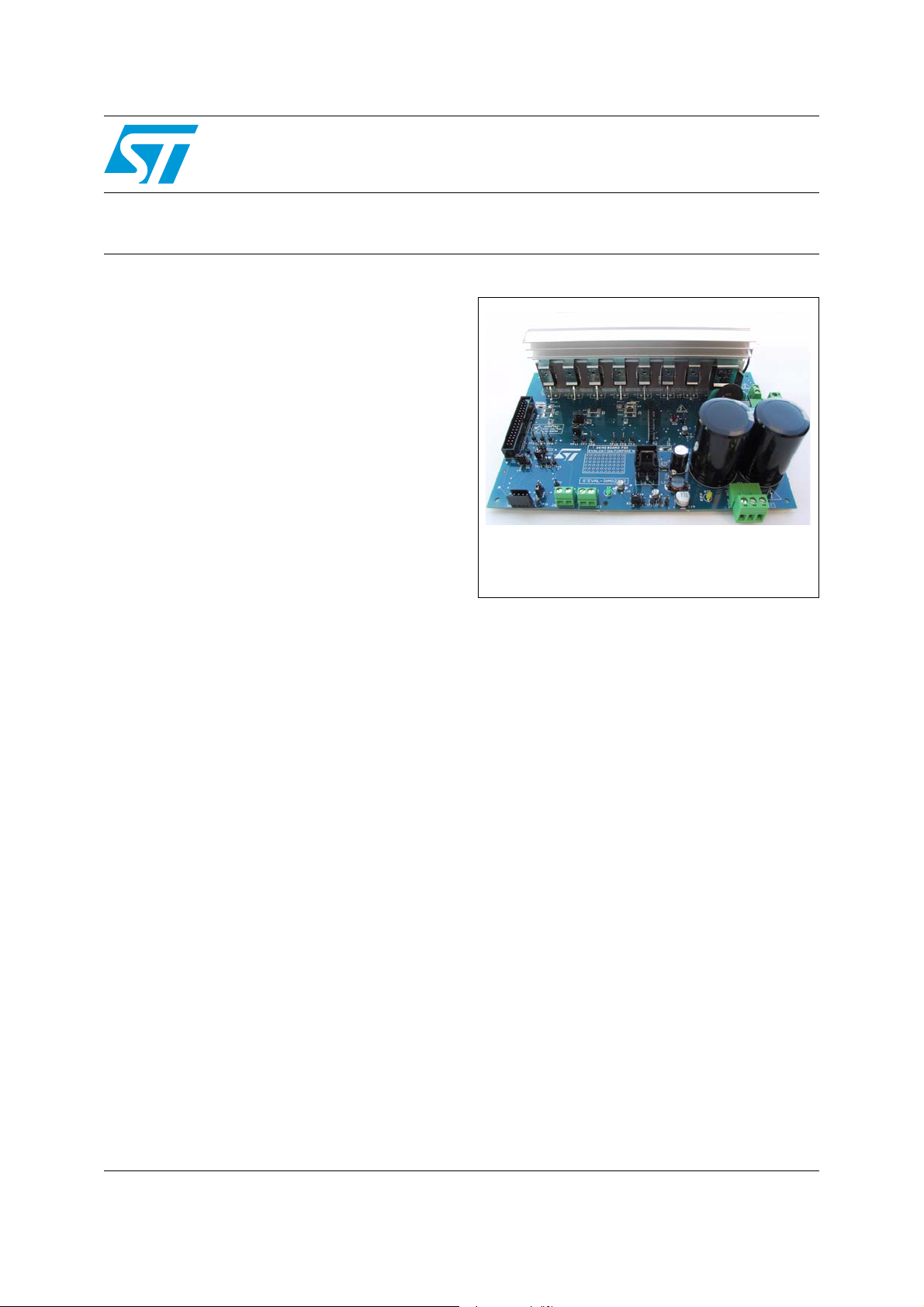
The STEVAL-IHM023V2 demonstration board
implements a 1 kW three-phase motor control
featuring the L6390 high and low-side drivers and
STEVAL-IHM023V2
L6390 drivers and STGP10NC60KD IGBT
Data brief
STEVAL-IHM023V2
the STGP10NC60KD IGBT. The demonstration
board is an AC/DC inverter that generates a
three-phase waveform for driving three- or twophase motors such as induction motors or PMSM
motors up to 1000 W with or without sensors.
The STEVAL-IHM023V2 is a universal, fully
evaluated and populated design consisting of a
three-phase inverter bridge based on
STMicroelectronics’ 600 V IGBT
STGP10NC60KD in a TO-220 package mounted
on a heatsink and the L6390 high-voltage highside and low-side driver featuring an integrated
comparator for hardware protection features such
as overcurrent and overtemperature.
The driver also integrates an operational amplifier
suitable for advanced current sensing. Thanks to
this advanced characteristic, the system has been
specifically designed to achieve an accurate and
fast conditioning of the current feedback, thus
matching the typical requirements in field oriented
control (FOC).
The board has been designed to be compatible
with single-phase mains, supplying from 90 VAC
to 285 VAC or from 125 VDC to 400 VDC for DC
voltage. With reconfiguration of the input
sourcing, the board is suitable also for low-voltage
DC applications up to 35 VDC.
September 2011 Doc ID 022260 Rev 1 1/9
For further information contact your local STMicroelectronics sales office.
www.st.com
9
Schematics STEVAL-IHM023V2
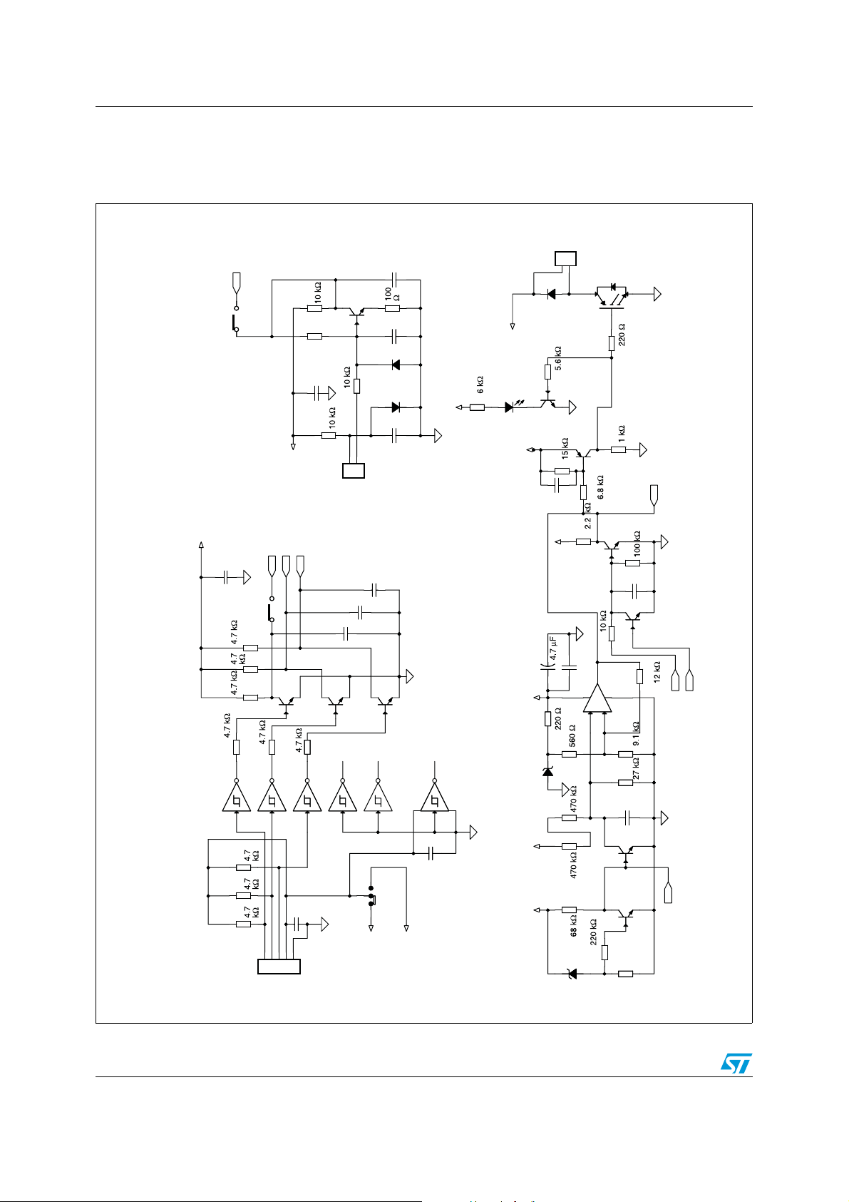
1 Schematics
Figure 1. STEVAL- IHM023V2 schematic - part 1
1
2
J6
D26
Q18
C25
+
+
STTH2L06
R121
BC847
R30
1nF
1nF
C75
C75
+15V
R25
Q2
R28
C26
5
R Brake
BC857B
100 nF
-
-
3
Q3
STGP10NC60KD
R18
Q5
R33
1
U4
+
+
4
R21
R26
BC847
Q14
TS391ILT
2
R32
R35
C65
100
pF
BC847
R34
Vdd_micro
W7 Tach o
C73
R111
R110
R109
R115
M_phase_A
100 nF
W4 H1/A +
Q15
R116
BC847
Tacho sensor
M_phase_A
Vdd_micro
M_phase_B
M_phase_C
R117
R20
R19
C24
Q17
N.C.
100 nF
R22
C69
BC847
J8
C74
10 pF
Q4
BC847
BAT48JFILM
BAT48JFILM
R27
1
2
C70
10 pF
2
D1
1
D1
o
Tach
10 pF
Q16
BC847
C29
2.2 nF
R29
C28
100
C27
100 nF
nF
+15 V
R120
5.
+Bus
D28
LED Red
+15 V
+15 V
Brake control
R107
Hall/encoder
U11B
U11C
U11D
U11A
M74HC14M1R
1 2
M74HC14M1R
M74HC14M1R
3 4
5 6
U11E
M74HC14M1R
M74HC14M1R
9 8
R114
1
R113
2
12345
H3/Z+
H1/A+
H2/B+
+ 3.3/5 V
C71
GND
100 nF
Encoder/hall
R112
J4
J4
3
Vdd_micro
11 10
AB
M74HC14M1R
U11F
14
W16
+5 V
13 12
C72
100 nF
R31
D29 B ZX84B13V
R105
4.7 nF
C30
Q13
BC847
Q12
BC847
R106
220R
+Bus
+15 V
R24
R23
R104
D25
BZX84B13V
7
AM07502
Brake control
voltage off
Software brake
voltage off
2/9 Doc ID 022260 Rev 1
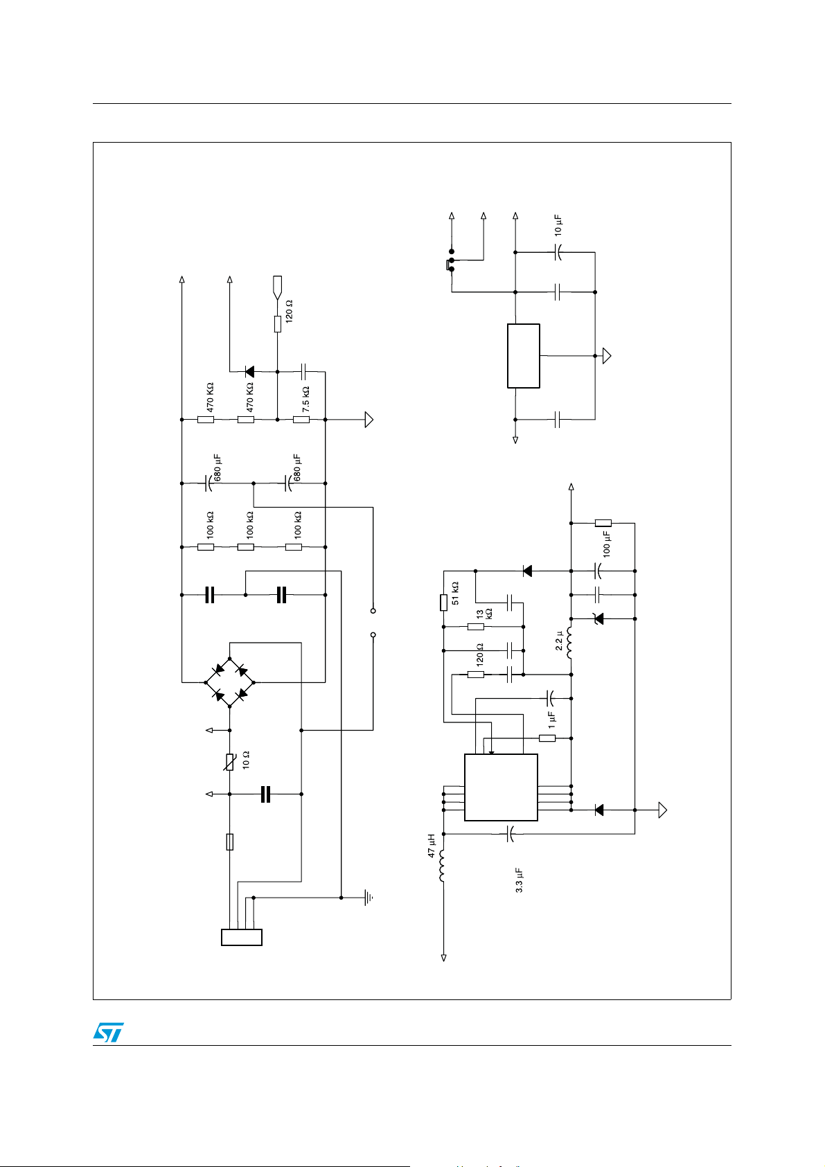
STEVAL-IHM023V2 Schematics
Figure 2. STEVAL- IHM023V2 schematic - part 2
Input part with bridge
C8
+
+
C7
100 nFC7100 nF
V
/6.3
Vdd_ micro
+5 V
+3.3 V
1
+Bus
Vdd_m icro
Bus_voltage
W1
2
3
AM07503
2
D2
BAT48JFILM
R5
C9
10 nF
OUT
1
GND
IN
3
R4
R2
/250 V
C2
+
+
R3
R1
C1
4.7 nF/Y2
D1
DC_bus_voltage
-+
-+
R7
/250 V
C3
+
+
R6
C5
4.7 nF/Y2
W14
tage_douVol bler
U1 LD1117S33TR SOT223
C14
R10
R8
C13
N.C.
R9
C12
47 nF
+5 V
D6
220 nF
C6
100 nF
STTH1L06A
L2 HL2
+
+
+15 V
C19
C18
N.C.
R12
/25 V
+
+
100 nF
D9
BZV55C18SMD
KBU6K
relay_ Brelay_ A
VR1
U3 VIPer16LD
C4
C4
F1 FUSE-1
6.25 A TEMP
/X 2
150 nF
L1L1
123
4
J1
INPUT
6
5
VDD
Buck converter +3.3 V linear
Drain1
16
Drain2
15
Drain3
14
Drain4
13
8
7
FB
LIM
Source1
Source2
Source3
Source4
+
+
C15
COMP
/450 V
/50 V
C16
N.C.
R108
1
2
3
4
D8
STTH1L06A
Viper
Doc ID 022260 Rev 1 3/9

Schematics STEVAL-IHM023V2
Figure 3. STEVAL- IHM023V2 schematic - part 3
+15 V
AM07504
D3
STPS1150
D3
C11
+5 V
100 nF
LV DC bus supply
U2
LM7805_0
3
D5
1N4148
GND
C10
2
100 nF
1N4148
phase_ A
1
J7
J7
BEMF daughter board
+Bus
phase_ B
2
+3.3 V
phase_ C
3
567
4
OUT
IN
1
PWM_Vref
Vdd_ micro
8
2.54 linebar
C68
CAPACITOR POL_1
+
+
C66
100 nF
3
OUT
2
GND
+5 V linear
IN
U10 L78M05ACDT-TR DPAK
1
C67
100 nF
35 V max!
y
D4
SM6T36AD4SM6T36A
W3
LV-suppl
Vdd_micr o
+15 V
<35 V ONLY
HIGH VOLTAGE
+15 V
D7
LED green
R111
C17
100 nF
+15 V
relay_ A
+15 V ex. supplyMotor output
1
2
J3
+15 VDC
LS1
LS1
+Bus
Viper
relay_ B
12
14
FINDER 4031-12
2
1
11
D27
LED yellow
Motor connector
R14
J5
J5
1 2
3 4
Bus_voltage
6
5
182022
7 8
9 10
11 12
13 14
15 1617192123
W6 Vdd_mcu
Het_temperature
M_phase_C
24
25 26
27 28
29 30
31 32
33 34
Motor connector
R13
D10
1N4148
phase_A
phase_B
phase_C
NTC bypass
R103
123
J2
MOTOR
lay
NTC bypass re
4/9 Doc ID 022260 Rev 1
Q1
PWM-A-H
PWM-A-L
PWM-B-H
PWM-B-L
PWM-C-H
PWM-C-L
Curre nt_C
Curre nt_A
BC847
R17
Curre nt_B
PWM_Vref
M_phase_A
M_phase_B
2
NTC_bypass_relay
1
3
A
B
W5
OCP off EM_STOP
Software brake
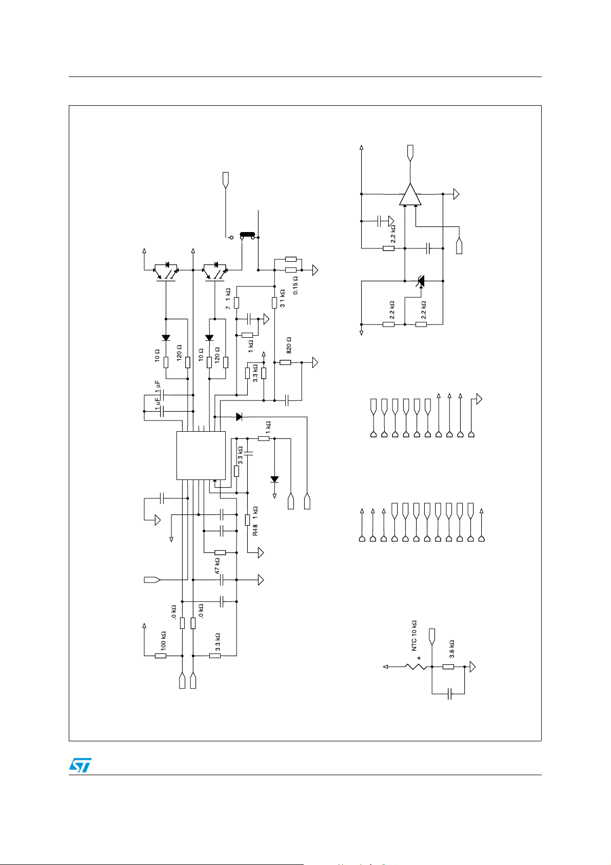
STEVAL-IHM023V2 Schematics
Figure 4. STEVAL- IHM023V2 schematic - part 4
+Bus
Q6
2
D131 N4148
R37
C33
C32
phase_A
STGP10NC60 kD
3
1
R39
15
13
14
16
U5L6390D
OUT
HVG
Vboot
STGP10NC60 kD
Q7
2
1
D141N4148
R41
R45
10
9
11
NC12NC
CP+
LVG
OP+
!SD
C_E
W9
3SH
N.C.
R56
1SH
C56
100 nF
R84
U8
TS391ILT
1
5
2
-
+
-
+
3
4
AM07505
C57
2
M_phase_C
470 pF
3
1
Het_temperature
R123
ref
+15 V
+3.3 V
Brake control
Bus_voltage
3
R55
C40
2.2 nF
R4
R50
R49 N.C.
R5
+3.3 V
R54
C41
R52
33 pF
U9
TS3431BILT
R122
ref +3.3 V
M_phase_A
M_phase_B
Current _C
D15BAT48JFILM
R51
TP22TP22
TP23TP23
TP14TP14
TP15TP15
TP16TP16
TP17TP17
TP19TP19
TP20TP20
TP21TP21
TP18TP18
470 nF
1 nF
C39 100 pF
R46
D16 BAT48JFILM
Vdd_micro
phase_A
phase_B
OCP off
Current_A
TP1TP1
TP2TP2
TP3TP3
phase_C
PWM-A-H
PWM-A-L
TP4TP4
PWM-B-H
PWM-B-L
TP6TP6
TP5TP5
PWM-C-H
PWM-C-L
Current _A
Current _B
+5 V
TP9TP9
TP8TP8
TP7TP7
TP10TP10
TP11TP11
TP24TP24
HV H/L side driver channel A
DT5OPOUT
!LIN1!SD/OD
HIN3Vcc4OP -
GND
6
7
330 pF
2
C31
8
C37
C36
+15 V
R43
!SD
+3.3 V
R38 1
R36
1
R40
C35
C34
R42
10 pF
10 pF
Het_temperature
RT1
R44
t
+3.3 V
C38
10 nF
Heatsink temperature Test pins Het NTC comparator
PW M-A- H
PW M-A- L
Doc ID 022260 Rev 1 5/9

Schematics STEVAL-IHM023V2
Figure 5. STEVAL- IHM023V2 schematic - part 5
HV H/L side driver channel B
C_E
AM07506
+3.3 V
R76
R78 3.
+Bus
STGP10NC60KD
Q8
phase_B
Q9
STGP10NC60KD
R68
R81
R8
R7
2
3
2
1
D171 N4148
R58
R60
D181 N4148
R62
C44
C43
3
R71
R6
N.C.
C49
2 nF
+3.3 V
R70
1
A
B
W111
3
1
2
R65
R73 N.C.
BAT48JFILM
D19
C51
33 pF
R77
15
16
U6L6390D
HVG
Vboot
!L IN1!S D/OD
330 pF
2
C42
14
13
OUT
HIN3Vcc4OP -
11
NC12NC
LVG
DT5OPOUT
6
9
10
CP+
OP+
R69
W10Gain_11
GND
7
8
C50 100 pF
D20 BAT48JFILM
C48
470 nF
C47
1 nF
+15 V
R64
!SD
+3.3 V
R5
R57
PWM-B-L
C46
10 pF
C45
10 pF
11
R6
R63
PWM-B-H
6/9 Doc ID 022260 Rev 1
R7
Vdd_micro
OCP off
Curre nt_B
!SD
C52
R74
330 pF
Vdd_micro
EM_STOP

STEVAL-IHM023V2 Schematics
Figure 6. STEVAL- IHM023V2 schematic - part 6
C_E
AM07507
HV H/L side driver channel C
+Bus
0
STGP10NC60KD
Q1
2
1
D21 1N4148
R83
C55
C54
C53
330 pF
U7L6390D
3
R86
15
16
Vboot
!LIN1!SD/OD
2
phase_C
2
14
13
OUT
HVG
HI N3Vcc4OP-
1SH
STGP10NC60KD
Q11
1
D22 1N4148
R88
11
10
9
NC12NC
CP+
LVG
OP+
DT5OPOUT
GN D
7
6
8
R91
3SH
W13
R102
N.C.
3
R101
2.2 nF
R95 1
R931kR93
1k
R9
+3.3 V
R100
N.C.
R96
C64
33 pF
D23BAT48JFILM
R981kR98
1k
C62 100 pF
R92 C63
D24 BAT48JFILM
C61
470 nF
C60
1 nF
+15 V
!SD
+3.3 V
R851
R82
PWM-C-L
R90
C59
10 pF
C58
10 pF
R871
R89
PWM-C-H
Vdd_ micro
R94 1kR94 1k
OCP off
Current_C
Doc ID 022260 Rev 1 7/9

Revision history STEVAL-IHM023V2
2 Revision history
Table 1. Document revision history
Date Revision Changes
26-Sep-2011 1 Initial release.
8/9 Doc ID 022260 Rev 1

STEVAL-IHM023V2
Please Read Carefully:
Information in this document is provided solely in connection with ST products. STMicroelectronics NV and its subsidiaries (“ST”) reserve the
right to make changes, corrections, modifications or improvements, to this document, and the products and services described herein at any
time, without notice.
All ST products are sold pursuant to ST’s terms and conditions of sale.
Purchasers are solely responsible for the choice, selection and use of the ST products and services described herein, and ST assumes no
liability whatsoever relating to the choice, selection or use of the ST products and services described herein.
No license, express or implied, by estoppel or otherwise, to any intellectual property rights is granted under this document. If any part of this
document refers to any third party products or services it shall not be deemed a license grant by ST for the use of such third party products
or services, or any intellectual property contained therein or considered as a warranty covering the use in any manner whatsoever of such
third party products or services or any intellectual property contained therein.
UNLESS OTHERWISE SET FORTH IN ST’S TERMS AND CONDITIONS OF SALE ST DISCLAIMS ANY EXPRESS OR IMPLIED
WARRANTY WITH RESPECT TO THE USE AND/OR SALE OF ST PRODUCTS INCLUDING WITHOUT LIMITATION IMPLIED
WARRANTIES OF MERCHANTABILITY, FITNESS FOR A PARTICULAR PURPOSE (AND THEIR EQUIVALENTS UNDER THE LAWS
OF ANY JURISDICTION), OR INFRINGEMENT OF ANY PATENT, COPYRIGHT OR OTHER INTELLECTUAL PROPERTY RIGHT.
UNLESS EXPRESSLY APPROVED IN WRITING BY TWO AUTHORIZED ST REPRESENTATIVES, ST PRODUCTS ARE NOT
RECOMMENDED, AUTHORIZED OR WARRANTED FOR USE IN MILITARY, AIR CRAFT, SPACE, LIFE SAVING, OR LIFE SUSTAINING
APPLICATIONS, NOR IN PRODUCTS OR SYSTEMS WHERE FAILURE OR MALFUNCTION MAY RESULT IN PERSONAL INJURY,
DEATH, OR SEVERE PROPERTY OR ENVIRONMENTAL DAMAGE. ST PRODUCTS WHICH ARE NOT SPECIFIED AS "AUTOMOTIVE
GRADE" MAY ONLY BE USED IN AUTOMOTIVE APPLICATIONS AT USER’S OWN RISK.
Resale of ST products with provisions different from the statements and/or technical features set forth in this document shall immediately void
any warranty granted by ST for the ST product or service described herein and shall not create or extend in any manner whatsoever, any
liability of ST.
ST and the ST logo are trademarks or registered trademarks of ST in various countries.
Information in this document supersedes and replaces all information previously supplied.
The ST logo is a registered trademark of STMicroelectronics. All other names are the property of their respective owners.
© 2011 STMicroelectronics - All rights reserved
Australia - Belgium - Brazil - Canada - China - Czech Republic - Finland - France - Germany - Hong Kong - India - Israel - Italy - Japan -
STMicroelectronics group of companies
Malaysia - Malta - Morocco - Philippines - Singapore - Spain - Sweden - Switzerland - United Kingdom - United States of America
www.st.com
Doc ID 022260 Rev 1 9/9
 Loading...