

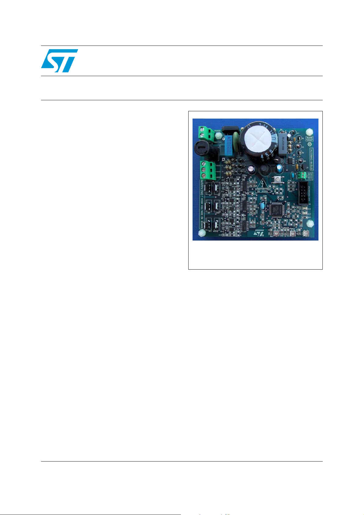
100 W 3-phase inverter for BLDC sensorless motor
Features
■ Wide range input voltage
■ Maximum power up to 100 W
■ 4.4 A, 520 V power MOSFET included
■ Compatible with power MOSFETs in IPAK
packages
■ 15 V auxiliary power supply connector
■ Programming and debugging support via 10-
pin ICC connector
■ Three potentiometers for runtime settings
■ Start/stop button
■ Reset button
Description
STEVAL-IHM017V1
evaluation board
Data Brief
This evaluation board is a complete development
platform for BLDC sensorless motor applications
with nominal power up to 100 W.
Based on a cost effective, flexible and open
design, it includes a 3-phase inverter bridge
based on the STD5NK52ZD-1 power MOSFET in
the IPAK package and an ST7MC 8-bit
microcontroller with 16 Kbyte internal Flash
memory.
The system has been designed to drive a 3-phase
brushless motor with permanent magnet rotor
exploiting trapezoidal sensorless control.
The STEVAL-IHM017V1 features complete
hardware for developing motor control
applications based on ST7MC peripherals
including motor control peripheral (MTC). It uses
an in-circuit communication (ICC) standard
interface to connect to the host PC via in-circuit
debuggers/programmers such as the inDART-STX
board from SofTec Microsystems™. The board is
designed to support a bus voltage of 230 Vac and
up to 100 W of input power. Also included is a
power supply stage with the VIPer12A-E as the
STEVAL-IHM017V1
buck converter to generate the voltage reference
for the driver and the microcontroller.
January 2008 Rev 1 1/5
For further information contact your local STMicroelectronics sales office.
www.st.com
5
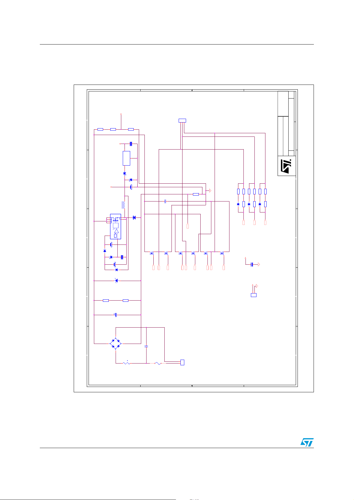
Circuit schematic STEVAL-IHM017V1
1 Circuit schematic
Figure 1. Schematic 1/2
A1
A1
A1
of
of
of
G.Rasconà
G.Rasconà
G.Rasconà
M.DiGuardo
M.DiGuardo
M.DiGuardo
11Wednesday,June 13, 2007
11Wednesday,June 13, 2007
ALL THE RESISTORS
ACCURACY MUST BE <1%
680KR2680K
1N4148D11N4148
100K-1/2W
100K-1/2W
R24
R24
HVMonitoring
R3
330KR3330K
+15V
IC1
IC1
5
6
7
8
DRAIN
DRAIN
4
VDD
VDD
C3
10uF/35V
C3
10uF/35V
D1
D3
1 2
BZX84C15D3BZX84C15
C2
TR1
TR1
12KR412K
R4
1uF/16V
16VC61uF/16V
16V
C6
+5V
1
Vout
2
GND
IC2
IC2
L78L05ACZ
L78L05ACZ
Vin
3
12
D5
D6
BZX85C5V1D5BZX85C5V1
BZX85C16D6BZX85C16
1 2
C5
100uF/25VC5100uF/25V
L1
1mH/350mAL11mH/350mA
TOKO 00499
VIPER12ADIP
VIPER12ADIP
2
1
D7
SOURCE
SOURCE
C4
1 2
see manual
22nF/50VC422nF/50V
100K-1/2W
100K-1/2W
R25
R25
STTH108D7STTH108
SET
RES
SET
RES
-
+
-
+
0.23V
0.23V
FB
FB
3
35V
35V
1 2
2.2uF/25VC22.2uF/25V
D2
STTH106D2STTH106
transil
transil
Q7
23
C8
STD5NK52 ZD-1Q7STD5NK52 ZD-1
23
1
BA2
BA1
1
R2
2
3
4
Phase B
Phase C
Phase A
J8
123
CON3J8CON3
R10
0.1R-2.5W
R10
0.1R-2.5W
22nF/400VC822nF/400V
LSCS
Q8
STD5NK52 ZD-1Q8STD5NK52 ZD-1
1
GNDBB1
BB2
Q9
23
Q10
STD5NK52 ZD-1
Q10
STD5NK52 ZD-1
STD5NK52 ZD-1Q9STD5NK52 ZD-1
23
23
1
1
GNDBD1
BC2
BD2
BC1
Q12
STD5NK52 ZD-1
Q12
Q11
Q11
STD5NK52 ZD-1
STD5NK52 ZD-1
STD5NK52 ZD-1
23
GNDBF1
1
1
BF2
BE2
BE1
R16 82KR16 82K
R65 1.2KR65 1.2K
R13 8 2KR13 82 K
R66 1.2KR66 1.2K
R64 1.2KR64 1.2K
D18 STTH106D18 STTH106
1 2
R12 82KR12 82K
BEMFA
R18 82KR18 82K
D20 STTH106D20 STTH106
D19 STTH106D19 STTH106
1 2
1 2
R17 82KR17 82K
R15 82KR15 82K
BEMFC
BEMFB
+15V
100nF/50VC9100nF/50V
C9
+15V
1
2
CON2CON2
11Wednesday,June 13, 2007
Drawn by:
Drawn by:
Drawn by:
1
SYSTEMS LAB
SYSTEMS LAB
SYSTEMS LAB
PowerBoard STD5NK52ZD
PowerBoard STD5NK52ZD
PowerBoard STD5NK52ZD
DocumentNumber Rev
Document Number Rev
Document Number Rev
Title:
Organisationname: Approvedby:
Organisationname: Approvedby:
Organisationname: Approvedby:
Title:
Title:
Size
Size
Size
Date: Sheet
Date: Sheet
Date: Sheet
R
R
R
RR
R
RR
R
RR
R
2
3
4
C1C1
D21
BRIDGE_2KPB**
D21
BRIDGE_2KPB**
-+
-+
5
15-5A
D D
C10
CAPNP 0.22uF 275V-X2
C10
CAPNP 0.22uF 275V-X2
NTCtNTC
t
F1
FUSE3AF1FUSE3A
C C
2/5
Neutral-Main
120/230-Vac
2
1
Phase-Main
J9
5
120/230VACJ9120/230VAC
B B
A A

STEVAL-IHM017V1 Circuit schematic
Figure 2. Schematic 2/2
R20
N.M.
R20
N.M.
1
2
3
+5V
4
5
BA2
BC807-25Q1BC807-25
Q1
D22
D22
STTH1L06A
STTH1L06A
220RR5220R
R5
R1
100RR1100R
C7
2.2uF-16VC72.2uF-16V
L6386D
L6386D
IC5
IC5
+5V
R38
100K
R38
100K
BEMFA
BEMFB
BEMFC
BA1
BB2
321
N.M.
N.M.
R22
R22
C13100pF C13100pF
STTH1L06A
STTH1L06A
220RR7220R
R7
D23
D23
R21
22R
R21
22R
9
14
12
10
13
NC11NC
HVG
OUT
VBOOT
LIN1SD2HIN3VCC4DIAG5CIN6GND
C22
C22
+15V
+5V
+5V
+5V
R54
47K
R54
47K
R52
47K
R52
47K
1
3
5
7
+5V
9
J7
ICCconnector :HE10 male typeJ7ICCconnector :HE10 male type
S2
SWPUSHS2SWPUSH
STRAP
Q2 BC807-25Q2 B C807-25
C14
C14
100pF
100pF
R6 100RR6 100R
8
LVG
7
1nF
1nF
C24
C24
R40
R40
2
4
6
8
10
GNDBB1
321
R26
R26
N.M.
N.M.
C11
C11
GND
25V
25V
470nF
470nF
R59
10K
R59
10K
100K
100K
C37
C37
BC2
Q3 BC807-25Q3 B C807-25
321
D24
D24
R9
220RR9220R
STTH1L06A
STTH1L06A
R8
100RR8100R
2.2uF-16V
2.2uF-16V
14
13
HVG
VBOOT
LIN1SD2HIN3VCC4DIAG5CIN6GND
IC3 L6386DIC3 L6386D
R191KR19
R39
10K
R39
10K
1nF
1nF
C39
C39
47pF N.M
47pF N.M
47pF N.M
47pF N.M
C38
C38
C41
C41
BD2
BC1
Q4
N.M.
N.M.
D25
D25
R14
R14
C15
C15
R35
R35
100pF
100pF
STTH1L06A
STTH1L06A
R11
100R
R11
100R
R31 22RR31 22R
9
8
12
10
NC11NC
LVG
OUT
GND
7
C17
C17
1K
C23
C23
+15V
47pF N.M
47pF N.M
BE2
BC807-25Q4BC807-25
GNDBD1
321
D26
D26
C16
C16
100pF
100pF
STTH1L06A
STTH1L06A
220R
220R
R36 N.M.R36 N.M.
C12
C12
2.2uF-16V
2.2uF-16V
R23
12K
R23
12K
C18
N.M.
C18
N.M.
R46
R46
1.5K
1.5K
1nF
1nF
25V
25V
470nF
470nF
IP
41
44
36
38
37
40
VPP
MCO0 (HS)42MCO1 (HS)43MCO2 (HS)
PE2/ICAP2_B39PE3/ICAP1_B
PD7 (HS)/TDO
PE1/OCMP1_B
PEO (HS)/OCMP2_B
IC6
IC6
MCO3 (HS)1OSC15OSC26Vss_17Vdd_18PA3/PWM0/AIN09PA5/ARTIC1/AIN110PB0/MCVREF11PB1/MCIA12PB2/MCIB13PB3/MCIC14PB4/MISO15PB5/MOSI/AIN3
MCO5 (HS)3MCO4 (HS)2MCES
4
LS
+5V
X1
BE1
BC807-25Q5BC807-25
Q5
321
R32
R32
C19
C19
220R
220R
100pF
100pF
R37
22R
R37
22R
R30
100R
R30
100R
14
12
13
HVG
OUT
L6386D
L6386D
VBOOT
IC4
IC4
LIN1SD2HIN3VCC4DIAG5CIN6GND
RBC
470nF
470nF
100nF
100nF
+5V
28
35
32
29
34
31
33
30
RESET
PD6 (HS)/RDI
PD3/ICAP1_A/AIN13
PD5/AIN15/ICCDATA
PD0/OCMP2_A/AIN11
PD2/ICAP2_A/MCZEM/AIN12
PD4/EXTCLK_A/AIN14/ICCCLK
PD1 (HS)/OCMP1_A/MCPWMV/MCDEM
PB6 (HS)/SCK17PB7 (HS)/SS/AIN418PC2/OAP19PC3/OAN20OAZ/MC CFI1/AIN 621PC4/MCCREF
16
C30
10nF
C30
10nF
C28
C28
100nF
100nF
BF2
BC807-25Q6BC807-25
Q6
GNDBF1
321
N.M.
N.M.
D27
D27
C20
C20
R34
R34
100pF
100pF
220R
220R
STTH1L06A
STTH1L06A
R47
R47
R33
100R
R33
100R
9
8
10
NC11NC
LVG
GND
7
1nF
1nF
C48
C48
C25
C25
+15V
25V
25V
470nF
470nF
C50
1uF
C50
R60
R60
+5V
C34
C34
C42
C42
25V
25V
27
25
26
24
23
VSSA
VSS_0
VDD_0
VAREF
PC7/MCPWMW/AIN7
1uF
100R
100R
R63R63
C51
10nF
C51
10nF
R62R62
C52
10nF
C52
10nF
R61R61
C49
10nF
C49
10nF
Not Mount
R43
27K
R43
27K
+5V
R56
33K
R56
33K
ST7FMC2S4T6-TQFP44
ST7FMC2S4T6-TQFP44
C40
100nF
C40
100nF
R55
68K
R55
68K
G.RASCONA'
G.RASCONA'
G.RASCONA'
M.DI GUARDO
M.DI GUARDO
M.DI GUARDO
Drawn by:
Drawn by:
Drawn by:
SYSTEMS LAB
SYSTEMS LAB
SYSTEMS LAB
<Title>
<Title>
<Title>
Document Numb er Rev
Document Numb er Rev
Document Numb er Rev
Organisationname: Approvedby:
Organisationname: Approvedby:
Organisationname: Approvedby:
Title:
Title:
Title:
This drawing may not be reproducedto a third partyunless permission is obtained in writingfrom ST MICROELECTRONICS
Size
Size
Size
Title
Size Document Numb er Rev
Title
Size Document Numb er Rev
Title
Size Document Numb er Rev
R
R
R
RR
R
RR
R
RR
R
22
C36
N.M
C36
N.M
R53
t.b.d.
R53
t.b.d.
R42
10K
R42
10K
R51
56K
R51
56K
R41
10K
R41
10K
short
connection
+5V
Not Mount
LSCS
AC
D13
D13
D12
D12
LED
LED
LED
LED
A C
R44
2.7K
R44
2.7K
R45
2.7K
R45
2.7K
1
A1
A1
A1
of
of
11Thursday,October 18,2007
11Thursday,October 18,2007
11Thursday,October 18,2007
11Thursday,October 18,2007
11Thursday,October 18,2007
11Thursday,October 18,2007
<Doc> <RevCode>
<Doc> <RevCode>
<Doc> <RevCode>
2
A3
A3
A3
Date: Sheet of
Date: Sheet
Date: Sheet
Date: She et of
Date: She et of
Date: Sheet of
Remark: All two leads components are 0805 except if not
available
3
4
5
CSTCE16MOV53-ROX1CSTCE16MOV53-RO
D D
C C
B B
A A
3/5

Revision history STEVAL-IHM017V1
2 Revision history
Table 1. Document revision history
Date Revision Changes
23-Jan-2008 1 Initial release
4/5

STEVAL-IHM017V1
Please Read Carefully:
Information in this document is provided solely in connection with ST products. STMicroelectronics NV and its subsidiaries (“ST”) reserve the
right to make changes, corrections, modifications or improvements, to this document, and the products and services described herein at any
time, without notice.
All ST products are sold pursuant to ST’s terms and conditions of sale.
Purchasers are solely responsible for the choice, selection and use of the ST products and services described herein, and ST assumes no
liability whatsoever relating to the choice, selection or use of the ST products and services described herein.
No license, express or implied, by estoppel or otherwise, to any intellectual property rights is granted under this document. If any part of this
document refers to any third party products or services it shall not be deemed a license grant by ST for the use of such third party products
or services, or any intellectual property contained therein or considered as a warranty covering the use in any manner whatsoever of such
third party products or services or any intellectual property contained therein.
UNLESS OTHERWISE SET FORTH IN ST’S TERMS AND CONDITIONS OF SALE ST DISCLAIMS ANY EXPRESS OR IMPLIED
WARRANTY WITH RESPECT TO THE USE AND/OR SALE OF ST PRODUCTS INCLUDING WITHOUT LIMITATION IMPLIED
WARRANTIES OF MERCHANTABILITY, FITNESS FOR A PARTICULAR PURPOSE (AND THEIR EQUIVALENTS UNDER THE LAWS
OF ANY JURISDICTION), OR INFRINGEMENT OF ANY PATENT, COPYRIGHT OR OTHER INTELLECTUAL PROPERTY RIGHT.
UNLESS EXPRESSLY APPROVED IN WRITING BY AN AUTHORIZED ST REPRESENTATIVE, ST PRODUCTS ARE NOT
RECOMMENDED, AUTHORIZED OR WARRANTED FOR USE IN MILITARY, AIR CRAFT, SPACE, LIFE SAVING, OR LIFE SUSTAINING
APPLICATIONS, NOR IN PRODUCTS OR SYSTEMS WHERE FAILURE OR MALFUNCTION MAY RESULT IN PERSONAL INJURY,
DEATH, OR SEVERE PROPERTY OR ENVIRONMENTAL DAMAGE. ST PRODUCTS WHICH ARE NOT SPECIFIED AS "AUTOMOTIVE
GRADE" MAY ONLY BE USED IN AUTOMOTIVE APPLICATIONS AT USER’S OWN RISK.
Resale of ST products with provisions different from the statements and/or technical features set forth in this document shall immediately void
any warranty granted by ST for the ST product or service described herein and shall not create or extend in any manner whatsoever, any
liability of ST.
ST and the ST logo are trademarks or registered trademarks of ST in various countries.
Information in this document supersedes and replaces all information previously supplied.
The ST logo is a registered trademark of STMicroelectronics. All other names are the property of their respective owners.
© 2008 STMicroelectronics - All rights reserved
STMicroelectronics group of companies
Australia - Belgium - Brazil - Canada - China - Czech Republic - Finland - France - Germany - Hong Kong - India - Israel - Italy - Japan -
Malaysia - Malta - Morocco - Singapore - Spain - Sweden - Switzerland - United Kingdom - United States of America
www.st.com
5/5
 Loading...