

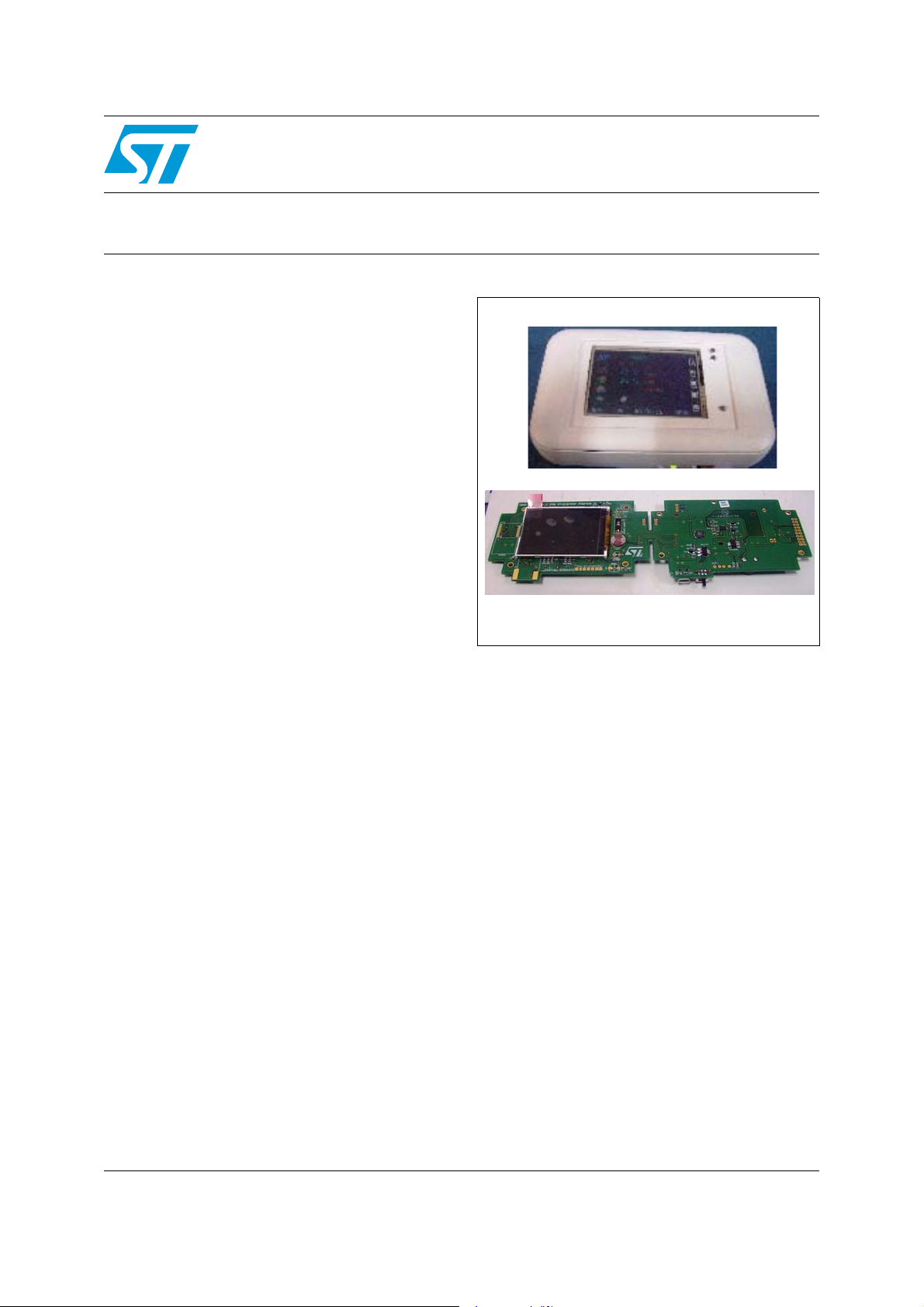
Smart monitoring node based on the STM32F103xx
Features
■ Low data rate wireless (ZigBee
implementation
■ Displays multiple sensor parameters for itself
and also the other wireless nodes associated
to it in star network
■ MEMS, temperature, resistive, humidity, light
intensity sensors
■ Manual or programmable control of nodes from
the station
■ TFT display with touchscreen menu navigation
■ GUI for logged data reading, saving and
analysis using graphs
■ Rechargeable Li-ion battery. Operation
possible without battery also using mini-USB to
power up the system
®
)
STEVAL-IFS015V1
and LIS331DLH
Data brief
STEVAL-IFS014V1
Description
The system, called smart monitoring station, is a
handheld device which works as the hub for low
data rate wireless network based on ZigBee
protocol to which all the nodes (smart monitoring
nodes - STEVAL-IFS015V1) are connected. This
system measures the temperature, humidity and
light intensity and gathers information of various
sensors (temperature, humidity, light intensity and
MEMS) from nodes placed at different locations. It
can also configure the alarm thresholds for the
parameters of all the connected nodes, as well as
for itself. Lights (or any other AC load) connected
to nodes may be controlled through the smart
monitoring station with addition of a few
components and its status is available on the
smart monitoring station display.
The system has a user interface with the graphic
menu, color TFT display (240 x 320) and
touchscreen. Data logging and analysis of logged
data can be done using the GUI developed for this
system.
This demonstration board can be powered up
using 3.7 V Li-ion battery. Alternatively it can work
with USB power without battery. When the battery
is mounted, the same USB charges the battery
®
and operates the system.
April 2009 Doc ID 15581 Rev 1 1/8
For further information contact your local STMicroelectronics sales office.
www.st.com
8

Circuits schematics STEVAL-IFS015V1
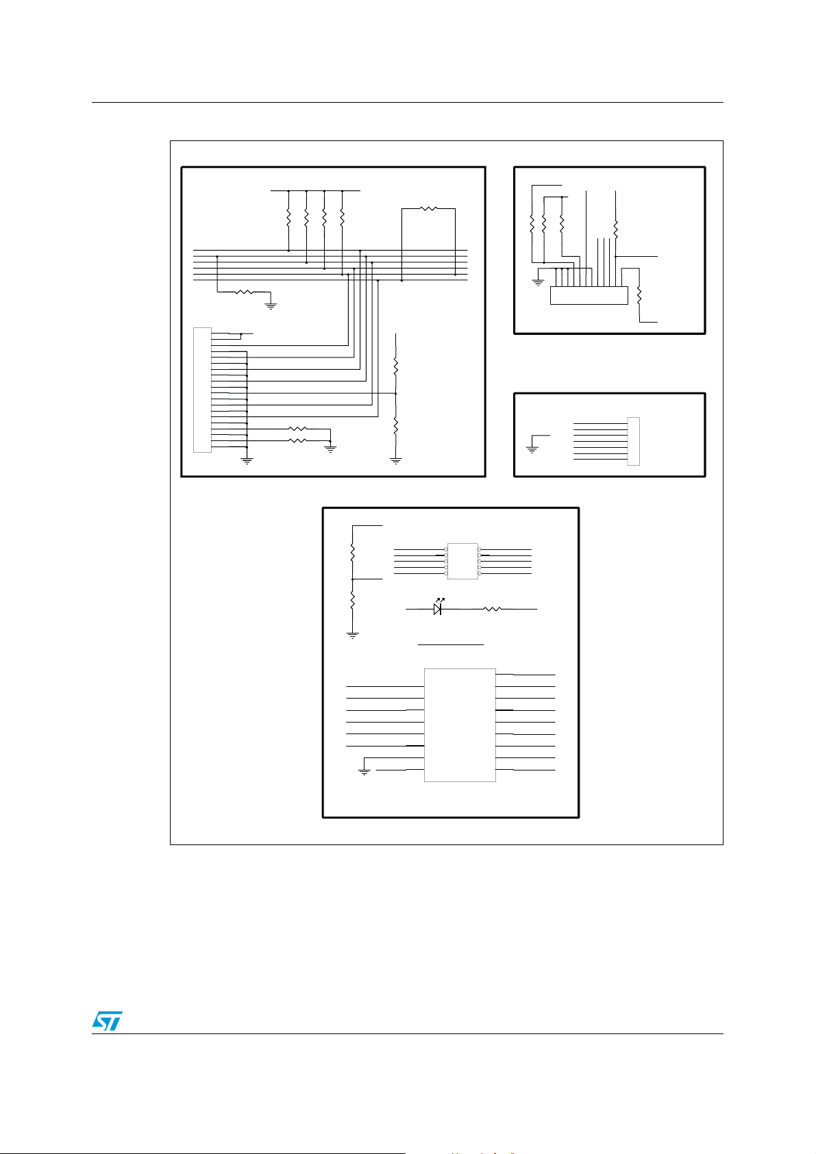
1 Circuits schematics
Figure 1. Power supply
C21
10uF
3V0//3V0//
1k
R62
2
OUT
GND
1
IN
U3
LD1117STR/SOT223
3
4V5//
4
5
6
C2
100nF
SW1
POWER SWITCH
1
2
3
D4
3
1.4k
R6
C3
100nF
STPS1L30A
STPS1L30A
D5
100
R11
100k
R3
3
180k
R1
3V0//
5V0_BAT
VBAT1
L6920D
U2
STN3PF06
Q1
PB8_LOW_BAT//
uF
47
C20
R12
15k
3
8
2
LB1
OUT
LX
FB
7
1
L1
uH
22
C19
VBAT1
1
BT1
C23
10nF
R15
10k
R14
10k
SHDN
5
LB0
SHDN
GND
REF
4
100nF
C4
uF
47
+
2
3.7V_LiION
5V0_BAT
6
R9
470
8
470
R
3
YELLOW
D
3
2
1
BAT
VCC
STBC08PMR
U1
6
SB
5V0_U
VBAT1
3
VCC
SS
OUT#
V
1
SHDN
STM1061N29WX6F
2
U12
CHRG
GND
POWER ON
100nF
C1
C33
47nF
3V0//
4
PROG
5
2k7
R7
POWER LED
220
R1
GND
D2
AM03786v1
2/8 Doc ID 15581 Rev 1
STEVAL-IFS015V1 Circuits schematics
Figure 2. Connectors - ZiGBee®, microSD and JTAG
PC4_
J2
10
11
12
13
14
15
16
17
18
19
20
JTAG_20
GND
SD_CD
3V0
R4
R5
R10
470
100k
J4
CON12
100k
10
11
12
SPI1_MISO
SPI1_SCK
5
6
7
8
9
GND
I2C2_SCL
3V0
I2C2_SDA
PC5_TK_RESET
PB1_TK_TINT
PB0_TK_GINT
3
R16
10k
R17
10k
1
3V0//
1
2
2
3
3
4
5
6
7
8
9
PB4_JTAG//
4
5
PA15_JTAG_
6
7
8
9
10
11
12
13
14
15
16
17
18
19
20
SWD//
PA13_JTAG_SWD//
PA14_JTAG_SWD//
RTCK
PB3_JTAG_S
WD//
RESET#//
R18
DBGRQ
10k
R
19
DBGACK
10
k
0V3//0V
//
SET#//
RE
3V0//
R32
not used
R2
10k
3
R29
0
JTAG connectors
PB4_JTAG//
R20
R21
R22
10k
10k
10k
SPI1_MOSI
3V0
4
3V0
R33
4k7
PE6_M
1
2
3
J
1
2
3
4
5
6
7
MicroSD card connector
SD_CS
R6
100k
3V0
3
1
2
3
4
5
6
7
TOUCH
KEY CONN
SDB
G
R66
511
SPZ_SDBG
R65
0
PC8_nRESET
PC6_n
HOST_INT
SPI2_nSSEL
SPI2_MOSI
SPI2_MISO
SPI2_SCK
3V0
PTI_DATA
SPZ_RSTB
SIF_SCLK
S
IF_MOSI
SIF_MISO
3V0
J9
1
3
5
7
9
HEADER 5X2
D1
ZIGBEE ACTIVITY LED
PC
8_nRESET SPZ_RSTB
U4
1
RSTB
2
HO
ST_INT
3
SP
I_SSEL
4
MOSI
5
MI
SO
6
SCLK
7
GND
8
VBRD
SPZB260
ZigBee module
2
4
6
8
10
S_DBG
ACTIVITY
WAKE
PTI_DATA
PTI_EN
SIF_LOADB
SIF_MOSI
SIF_MISO
S
IF_SCLK
PTI_EN
SIF_LOADB
GND
SPZ_SDBG
3V0
R64
511
17
16
15
14
1
12
11
10
9
ACTIVITY
3
SDBG
ACTIVITY
PC7_nWAK
PTI_DATA
PTI_EN
SIF_LOADB
SIF_MO
SIF_MISO
SIF_SCLK
E
SI
AM03787v1
Doc ID 15581 Rev 1 3/8
 Loading...