

smart 3D orientation and click detection standalone device
Features
■ 3D orientation sensor: 3 orthogonal directions
(6 positions)
■ Embedded click/double-click functionality
■ Low power consumption
■ Power down mode
■ High shock survivability
■ -40 °C to +85 ° C temperature range
■ Excellent quality and reliability
■ Testable after assembly without movement
■ Housed in a small, thin 3x5x0.9 SMD package
■ ECOPACK
Applications
■ Image rotation in mobile phones and portable
devices
■ Digital photo frames
■ Orientation detection
■ Button replacement
■ Motion triggered wake up
Description
The FC30 is a stand-alone 3D orientation and
click/double-click detection device.
When in a steady position, it is able to detect 6
different orientations with respect to the gravity
field, with notification provided through dedicated
signal lines.
®
, RoHS and “Green” compliant
FC30
MEMS functional sensor:
LGA-14
The device can be used for image rotation
(portrait/landscape) and position-based
applications.
When a single or double mechanical tap is
detected, the FC30 provides an interrupt signal,
enabling a “mouse button-like” function for
intuitive man-machine interface solutions.
A power-down mode selectable through a
dedicated input pin ensures very low current
consumption in battery-operated devices.
The FC30 is available in an LGA-14 3x5x0.9mm
SMD plastic full-moulded package compliant with
lead-free, RoHS and halogen-free regulations.
Compatible with a -40
range, the FC30 is shipped in standard tape and
reels for automatic pick and place machines and
is washable after reflow due to its completely
sealed and hermetic structure.
(3 x5 x0 . 9mm)
° C to +85 ° C temperature
Table 1. Order codes
Order code Temp range (°C) Package Packing
FC30 -40 to +85 LGA-14 Tray
FC30TR -40 to +85 LGA-14 Tape and reel
February 2010 Doc ID 14752 Rev 2 1/13
www.st.com
13

Contents FC30
Contents
1 Pin configuration and description . . . . . . . . . . . . . . . . . . . . . . . . . . . . . . 3
2 Device functionality . . . . . . . . . . . . . . . . . . . . . . . . . . . . . . . . . . . . . . . . . 4
2.1 Orientation detection . . . . . . . . . . . . . . . . . . . . . . . . . . . . . . . . . . . . . . . . . 4
2.1.1 Output response vs. orientation . . . . . . . . . . . . . . . . . . . . . . . . . . . . . . . . 4
2.2 Tap detection . . . . . . . . . . . . . . . . . . . . . . . . . . . . . . . . . . . . . . . . . . . . . . . 5
2.3 Post assembly device verification . . . . . . . . . . . . . . . . . . . . . . . . . . . . . . . . 6
2.4 Power down . . . . . . . . . . . . . . . . . . . . . . . . . . . . . . . . . . . . . . . . . . . . . . . . 6
3 Electrical specifications . . . . . . . . . . . . . . . . . . . . . . . . . . . . . . . . . . . . . . 7
3.1 Electrical characteristics . . . . . . . . . . . . . . . . . . . . . . . . . . . . . . . . . . . . . . . 7
3.2 Absolute maximum ratings . . . . . . . . . . . . . . . . . . . . . . . . . . . . . . . . . . . . . 7
4 Device and technology information . . . . . . . . . . . . . . . . . . . . . . . . . . . . . 9
5 Application hints . . . . . . . . . . . . . . . . . . . . . . . . . . . . . . . . . . . . . . . . . . . 10
5.1 Soldering information . . . . . . . . . . . . . . . . . . . . . . . . . . . . . . . . . . . . . . . . 10
6 Package information . . . . . . . . . . . . . . . . . . . . . . . . . . . . . . . . . . . . . . . . 11
7 Revision history . . . . . . . . . . . . . . . . . . . . . . . . . . . . . . . . . . . . . . . . . . . 12
2/13 Doc ID 14752 Rev 2
FC30 Pin configuration and description
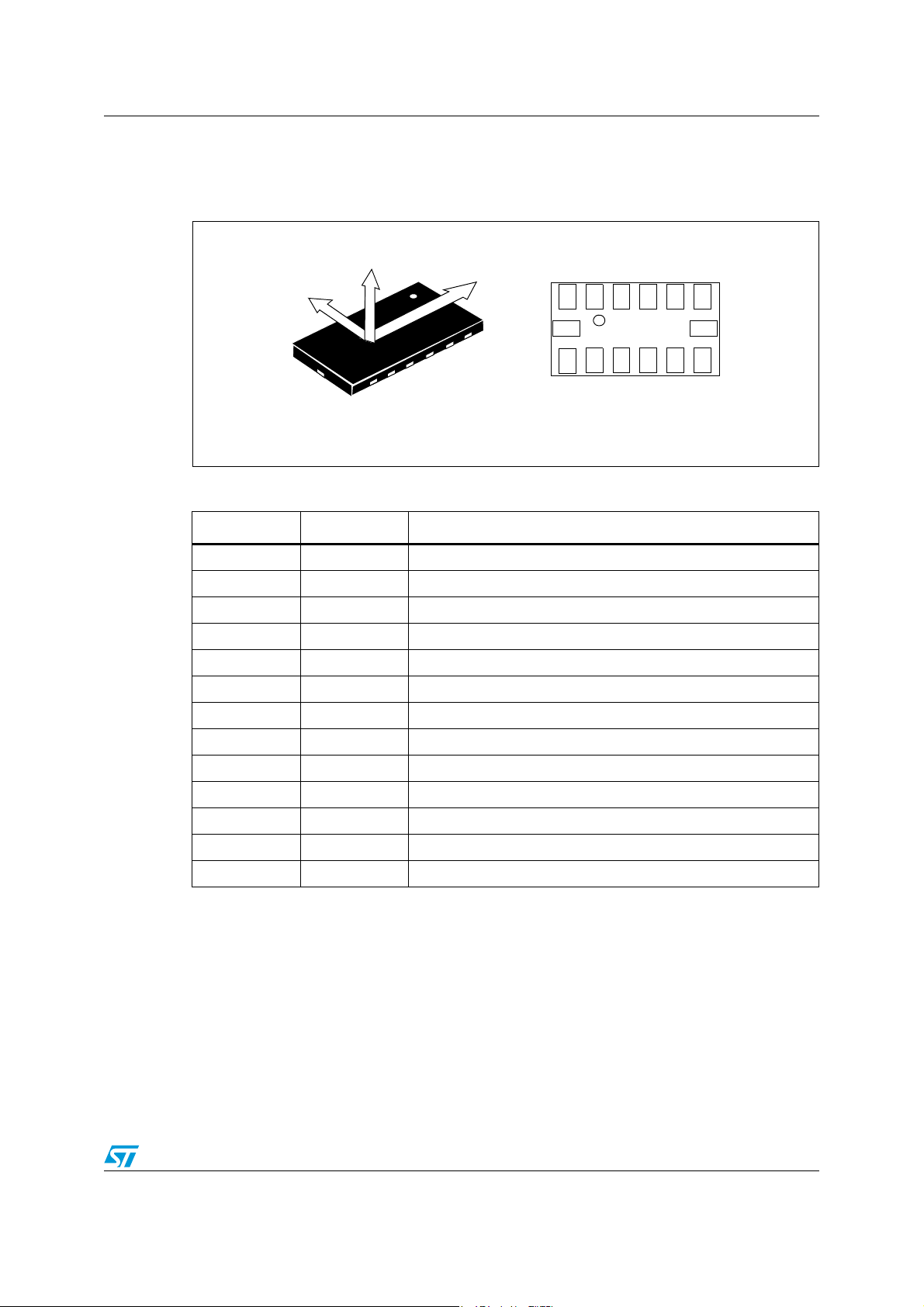
1 Pin configuration and description
Figure 1. Pin configuration
Face
Port
6
1
Land
13
8
TOP VIEW
Table 2. Pin description
Pin# Name Function
1 Vdd_IO Power supply for I/O pins
2 GND 0V supply
3 Vdd Power supply
4 Res Connect to 0V supply
5 GND 0V supply
6 Vdd Power supply
7 Res Leave unconnected
8 PC Portrait interrupt (logic 1: portrait orientation)
1
13 8
BOTTOM VIEW
6
9 LC Landscape interrupt (logic 1: landscape orientation)
10 Res Connect to 0V supply
11 PD Power-down (logic 0: power-down mode; logic 1: normal mode)
12 SIGN Sign interrupt for landscape/portrait/face orientation
13-14 Res Leave unconnected
Doc ID 14752 Rev 2 3/13
Device functionality FC30
2 Device functionality
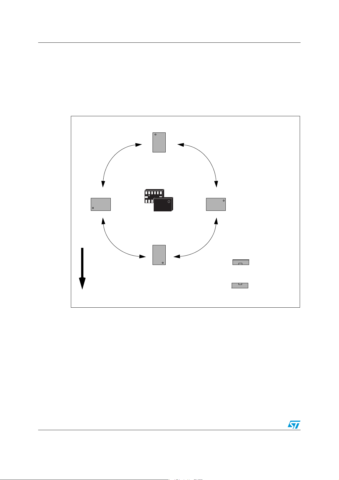
2.1 Orientation detection
The device output can be configured to provide its orientation relative to gravity based on
orientation definitions, as illustrated in Figure 2 below.
Figure 2. Orientation definitions
Por trai t U p
Landscape Left
FC30
Portrait Down
Gravity
2.1.1 Output response vs. orientation
Figure 3 shows the three interrupt output lines for the selected orientation.
Landscape Right
To p
Face Up
Bottom
Bottom
Face Down
To p
4/13 Doc ID 14752 Rev 2

FC30 Device functionality
Figure 3. Output response vs. orientation
LC = 1
PC = 0
PORT SIGN = 1
LEFT
RIGHT
LC = 1
PC = 0
PORT SIGN = 0
LC = 0
PC = 1
SIGN = 0
DOWNUP
LC = 0
PC = 1
SIGN = 1
Bottom
To p
To p
Bottom
LC = 0
PC = 0
SIGN = 1
LC = 0
PC = 0
SIGN = 0
Gravity
LANDSCAPE PORTRAIT FACE
2.2 Tap detection
The device can be configured to send an interrupt signal on a dedicated pin when “clicked”
in any direction (see Figure 4).
A more advanced feature also allows the detection of a “double click” event, with a
programmable time interval between the first and second click, to enable a “mouse buttonlike” functionality.
These functions can be fully programmed. For additional information, please contact your
local STMicroelectronics sales office.
Figure 4. Tap or “click” detection
LC or PC interrupts
FC30
Equipment with the FC30 mounted
Doc ID 14752 Rev 2 5/13

Device functionality FC30
2.3 Post assembly device verification
A special function allows the user to check the sensor functionality without moving the
device (device verification). This functionality is enabled by connecting the FC30 to an MCU.
For the connection scheme and additional information, please contact your local
STMicroelectronics sales office.
2.4 Power down
The power down function allows the device to be put in an ultra-low power consumption
mode by applying a "logic 0" voltage value to the PD pad. In this state the measurement
chain is powered off.
6/13 Doc ID 14752 Rev 2

FC30 Electrical specifications
3 Electrical specifications
3.1 Electrical characteristics
Table 3. Electrical characteristics
Symbol Parameter Test conditions Min. Typ.
Vdd Supply voltage 2.16 2.5 3.6 V
Vdd_IO I/O pins supply voltage 1.71 Vdd+0.1 V
Idd Supply current T = 25°C 0.3 0.4 mA
IddPdn
Ton Turn-on time
Ac Accuracy
Top Operating temperature range -40 +85 °C
Wh Product weight 30 mg
1. The product is factory calibrated at 2.5 V. The device can be used from 2.16 V to 3.6 V
2. All the parameters are specified @ Vdd=2.5 V, T = 25 °C unless otherwise noted
3. Typical specification are not guaranteed
4. Time to obtain valid data after exiting power-down mode
5. Accuracy defines the angle around the three orthogonal directions where orientation is detected (see Figure 5)
Current consumption in
power-down mode
(4)
(5)
(1) (2)
(3)
Max. Unit
T = 25°C 1 µA
30 ms
±3 deg
Figure 5. Orientation accuracy angle
Gravity
3.2 Absolute maximum ratings
Stresses above those listed as “absolute maximum ratings” may cause permanent damage
to the device. This is a stress rating only and functional operation of the device under these
conditions is not implied. Exposure to maximum rating conditions for extended periods may
affect device reliability.
Doc ID 14752 Rev 2 7/13
Accuracy

Electrical specifications FC30
Table 4. Absolute maximum ratings
Symbol Ratings Maximum Value Unit
Vdd,
Vdd_IO
Supply voltage and I/O pins supply voltage -0.3 to 6 V
Vin Input voltage on any control pin -0.3 to Vdd_IO +0.3 V
A
T
MAX
T
STG
Acceleration (any axis, powered and unpowered) 10000 g for 0.1ms g
Operating temperature range -40 to +85 °C
OP
Storage temperature range -40 to +125 °C
4.0 (HBM) kV
ESD Electrostatic discharge protection
200 (MM) V
1.5 (CDM) kV
This is a Mechanical Shock sensitive device, improper handling can cause permanent
damage to the part
This is an ESD sensitive device, improper handling can cause permanent damage to
the part
8/13 Doc ID 14752 Rev 2

FC30 Device and technology information
4 Device and technology information
The FC30 is an ultra-compact, low power 3-dimensional orientation and click/double-click
sensor. Manufactured with MEMS technology, the FC30 offers many advantages compared
to the conventional fabrication technology used nowadays in portable devices, including:
● Potential for additional strong miniaturization, leveraging the characteristics of
micromachining technology
● No surface friction effects, wear effects and acoustic noise generation
● Embedded electronic signal conditioning allows reduced power consumption
Doc ID 14752 Rev 2 9/13

Application hints FC30
5 Application hints
Figure 6. FC30 electrical connection for 3D orientation detection
Vdd
10uF
100nF
GND
PD
1
SIGN
6
Top VIEW
8
LC
PC
Digital signal from/to signal controller.Signal’s levels are defined by proper selection of Vdd_IO
13
Vdd_IO
Port
6
Face
8
TOP VIEW
1
Land
13
The diagram above refers to the electrical connection scheme for application of 3D
orientation detection.
The device core is supplied through the Vdd line while the I/O pads are supplied through the
Vdd_IO line. Power supply decoupling capacitors (100 nF ceramic, 10 µF Al) should be
placed as near as possible to pin 6 of the device (common design practice).
All the voltage and ground supplies must be present at the same time for proper behavior of
the IC (Figure 6).
5.1 Soldering information
The LGA package is compliant with the ECOPACK, RoHS and “green” standards. Leave the
pin 1 indicator unconnected during soldering. Land pattern and soldering recommendations
are available at www.st.com
10/13 Doc ID 14752 Rev 2

FC30 Package information
6 Package information
In order to meet environmental requirements, ST offers these devices in different grades of
ECOPACK
®
packages, depending on their level of environmental compliance. ECOPACK®
specifications, grade definitions and product status are available at: www.st.com. ECOPACK
is an ST trademark.
Figure 7. LGA-14: mechanical data and package dimensions
DIM.
A1 0.920 1.000 0.0362 0.0394
A2 0.700 0.0275
A3 0.180 0.220 0.260 0.0071 0.0087 0.0102
D1 2.850 3.000 3.150 0.1122 0.1181 0.1240
E1 4.850 5.000 5.150 0.1909 0.1968 0.2027
e0.800 0.0315
d0.300 0.0118
L1 4.000 0.1575
N1.360 0.0535
N1 1.200 0.0472
P1 0.965 0.975 0.9850.0380 0.03840.0386
P2 0.640 0.650 0.660 0.0252 0.0256 0.0260
T1 0.750 0.800 0.850 0.0295 0.0315 0.0335
T2 0.450 0.500 0.550 0.0177 0.0197 0.0217
R 1.200 1.600 0.0472 0.0630
h 0.150 0.0059
k 0.050 0.0020
i 0.100 0.003 9
s 0.100 0.0039
mm inch
MIN. TYP. MAX. MIN. TYP. MAX.
OUTLINE AND
MECHANICAL DATA
LGA-14 (3x5x0.92mm) Pitch 0.8mm
Land Grid Array Package
7773587 C
Doc ID 14752 Rev 2 11/13

Revision history FC30
7 Revision history
Table 5. Document revision history
Date Revision Changes
29-May-2008 1 Initial release
10-Feb-2010 2 Updated Table 2: Pin description.
12/13 Doc ID 14752 Rev 2

FC30
Please Read Carefully:
Information in this document is provided solely in connection with ST products. STMicroelectronics NV and its subsidiaries (“ST”) reserve the
right to make changes, corrections, modifications or improvements, to this document, and the products and services described herein at any
time, without notice.
All ST products are sold pursuant to ST’s terms and conditions of sale.
Purchasers are solely responsible for the choice, selection and use of the ST products and services described herein, and ST assumes no
liability whatsoever relating to the choice, selection or use of the ST products and services described herein.
No license, express or implied, by estoppel or otherwise, to any intellectual property rights is granted under this document. If any part of this
document refers to any third party products or services it shall not be deemed a license grant by ST for the use of such third party products
or services, or any intellectual property contained therein or considered as a warranty covering the use in any manner whatsoever of such
third party products or services or any intellectual property contained therein.
UNLESS OTHERWISE SET FORTH IN ST’S TERMS AND CONDITIONS OF SALE ST DISCLAIMS ANY EXPRESS OR IMPLIED
WARRANTY WITH RESPECT TO THE USE AND/OR SALE OF ST PRODUCTS INCLUDING WITHOUT LIMITATION IMPLIED
WARRANTIES OF MERCHANTABILITY, FITNESS FOR A PARTICULAR PURPOSE (AND THEIR EQUIVALENTS UNDER THE LAWS
OF ANY JURISDICTION), OR INFRINGEMENT OF ANY PATENT, COPYRIGHT OR OTHER INTELLECTUAL PROPERTY RIGHT.
UNLESS EXPRESSLY APPROVED IN WRITING BY AN AUTHORIZED ST REPRESENTATIVE, ST PRODUCTS ARE NOT
RECOMMENDED, AUTHORIZED OR WARRANTED FOR USE IN MILITARY, AIR CRAFT, SPACE, LIFE SAVING, OR LIFE SUSTAINING
APPLICATIONS, NOR IN PRODUCTS OR SYSTEMS WHERE FAILURE OR MALFUNCTION MAY RESULT IN PERSONAL INJURY,
DEATH, OR SEVERE PROPERTY OR ENVIRONMENTAL DAMAGE. ST PRODUCTS WHICH ARE NOT SPECIFIED AS "AUTOMOTIVE
GRADE" MAY ONLY BE USED IN AUTOMOTIVE APPLICATIONS AT USER’S OWN RISK.
Resale of ST products with provisions different from the statements and/or technical features set forth in this document shall immediately void
any warranty granted by ST for the ST product or service described herein and shall not create or extend in any manner whatsoever, any
liability of ST.
ST and the ST logo are trademarks or registered trademarks of ST in various countries.
Information in this document supersedes and replaces all information previously supplied.
The ST logo is a registered trademark of STMicroelectronics. All other names are the property of their respective owners.
© 2010 STMicroelectronics - All rights reserved
STMicroelectronics group of companies
Australia - Belgium - Brazil - Canada - China - Czech Republic - Finland - France - Germany - Hong Kong - India - Israel - Italy - Japan -
Malaysia - Malta - Morocco - Philippines - Singapore - Spain - Sweden - Switzerland - United Kingdom - United States of America
www.st.com
Doc ID 14752 Rev 2 13/13
 Loading...