

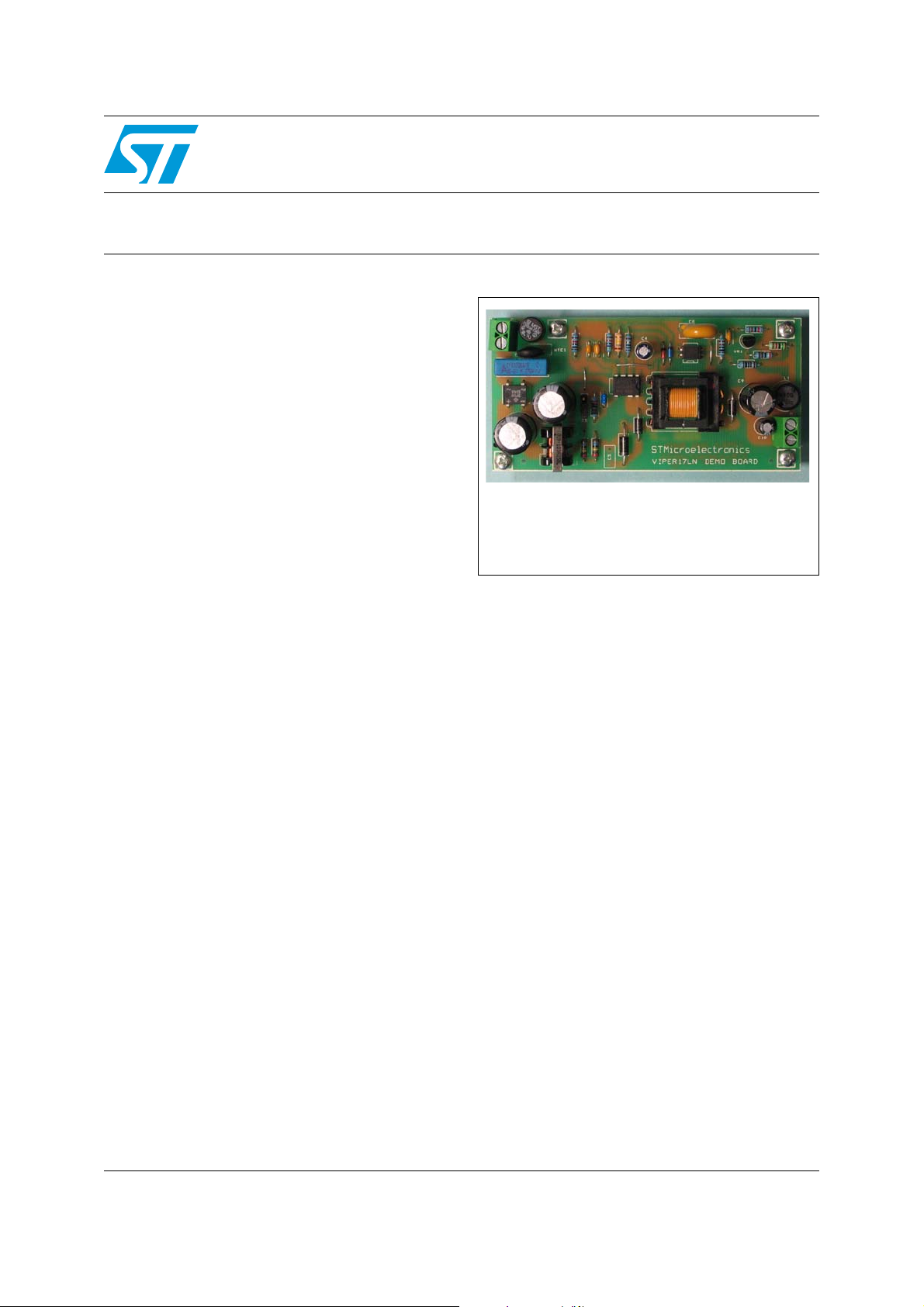
Demonstration board on 7 W single output
Features
■ Current mode with user set drain current
limitation
■ Frequency jittering
■ EMI regulation compliant
■ Low stand by consumption
■ High efficiency conversion
■ Over-load / output short circuit protection
■ Transformer saturation and secondary winding
short circuit protection (2
■ Output over-voltage protection (optional)
■ Brown out protection (optional)
Description
The new VIPer17 device integrates in the same
package two components: an advanced PWM
controller built in BCD6 technology and an 800 V
avalanche rugged vertical power MOSFET. The
device is suitable for off line power converter
operating both, with wide range input voltage (85
VAC - 270 VAC) up to 7 W or with single range
input voltage (85 VAC - 132 VAC or 175 VAC - 265
VAC). With European range input voltage (175
VAC - 265 VAC) the device can handle up to 10 W
of output power. The proposed solution has the
advantage of using few external components
compared to a discrete solution, providing several
switch mode power supply's protections and very
low stand by consumption in no load condition.
nd
OCP)
EVALVIPER17L-7W
based on the VIPer17
Data Brief
EVALVIPER17L-7W
brown out protections, improve the reliability and
safety of the design. More over internal thermal
shut down and an 800 V avalanche rugged power
MOSFET improve the robustness of the system.
The present demonstration board is a standard
one output isolated fly-back converter that uses
all the protections above mentioned. If not
necessary brown out protection and over-voltage
protection could be not used reducing the number
of external comp furthermore.
VIPer17 device operates at fixed frequency that
can be 115 kHz or 60 kHz according to the part
number selected. Frequency jittering is
implemented and it helps to meet the standards
regarding electromagnetic disturbance The
several protections present on the device like:
overload, output short circuit, secondary winding
short, hard transformer saturation protection and
June 2008 Rev 1 1/6
For further information contact your local STMicroelectronics sales office.
www.st.com
6
Board parameter and circuit schematic EVALVIPER17L-7W
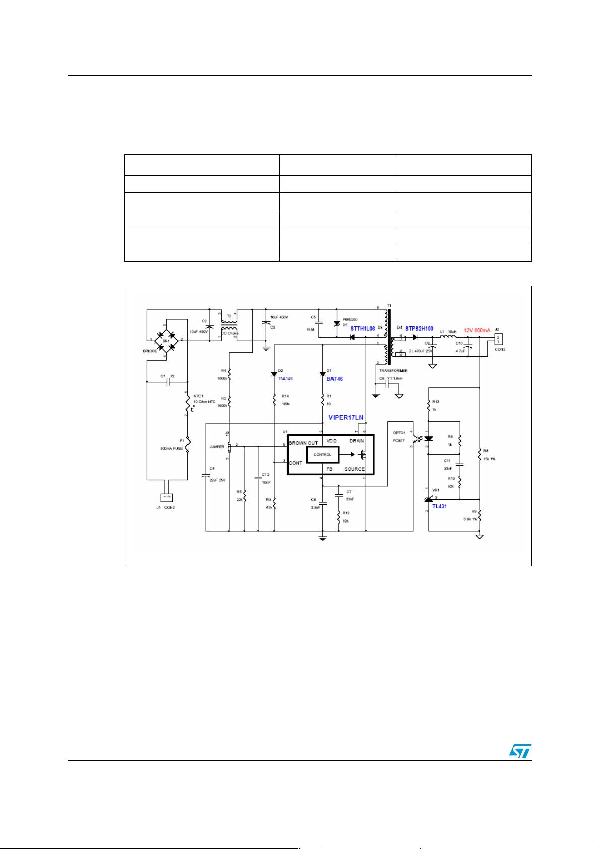
1 Board parameter and circuit schematic
Table 1. Demonstration board parameters
Parameter Symbol Value
Input voltage range V
Output voltage V
Max output current I
Precision of output regulation ∆V
High frequency output voltage ripple ∆V
Figure 1. EVALVIPER17L-7W schematic
IN
OUT
OUT
OUT_LF
OUT_HF
90V
RMS
600mA
– 265V
12V
±5%
50mV
RMS
2/6

EVALVIPER17L-7W Bill of material
Appendix A Bill of material
Table 2. BOM list
Item Qty. Reference Description Part/value
1 1 BR1 600 V 1 A diodes bridge DF06M
2 1 C1 100 nF X2 capacitor 100 nF x2 B32922
3 2 C2, C3 450V 10 µF electrolytic capacitor 450YXA10M12.5x20
4 1 C4 35 V 22 µF electrolytic capacitor
5 1 C5 Not mounted Not mounted
6 1 C6 25 V ceramic capacitor 1.8 nF
7 2 C7 25 V ceramic capacitor 33 nF
8 1 C8 Y1 2.2 nF capacitor Series 440L
9 1 C9 470 µF 25V electrolytic capacitor
10 1 C10
C11 25 V ceramic capacitor 330 nF
11 1 C12 10 nF
12 1 D1 Diode BAT46
13 1 D2 Diode 1N4148
14 1 D3 Diode STTH1L06
15 1 D4 Diode STPS2H100
16 1 D5 Transil P6KE250
17 1 F1 Fuse
18 2 J1,J2 Two screw connectors PK3502
25 V 47 µF electrolytic capacitor
rubycon ZLG
NRSA220M35V5x11
TR
Serie ZL 25 V 470 µF
10X16
50 V 4.7µF YK
TR5 250 V 500 mA
(fuse)
19 1 J3 3 Pin jumper (strip line) Jumper
20 1 L1 10 µH 1 A inductor ELC09D100E
21 1 NTC1 10 Ohm NTC B57153S0100M000
22 1 OPTO1 Opto coupler PC817
23 1 R1 10 Ohm resistor 1/4 W resistor
24 2 R2,R4 1600 kΩ 1% 1/4 W resistor 1% precision 1/4 W
25 1 R3 68 kΩ resistor 1% precision 1/4 W
26 1 R5 22 kΩ 1% 1/4 W resistor 1% precision 1/4 W
27 1 R6 1 kΩ resistor 1/4 W
28 1 R8 15 kΩ 1% 1/4 W resistor 1% precision 1/4W
3/6

Bill of material EVALVIPER17L-7W
Table 2. BOM list (continued)
Item Qty. Reference Description Part/value
29 1 R9 3.9 kΩ 1% 1/4 W resistor 1% Precision 1/4 W
30 1 R10 33 kΩ resistor 1/4 W
31 2 R14 220 kΩ resistor 1/4 W
32 1 R12 33 kΩ resistor 1/4 W
33 1 R13 1 kΩ resistor 1/4 W
34 1 T1 Switch mode power transformer
35 1 T2 Common mode choke for line filter BU9-103R25B
36 1 U1 VIPER17 (60 KHz, DIP-7) VIPER 17
37 1 VR1 Voltage reference TL431
Code: 1715.0009
REV1
4/6

EVALVIPER17L-7W Revision history
2 Revision history
Table 3. Document revision history
Date Revision Changes
05-Jun-2008 1 Initial release.
5/6

EVALVIPER17L-7W
Please Read Carefully:
Information in this document is provided solely in connection with ST products. STMicroelectronics NV and its subsidiaries (“ST”) reserve the
right to make changes, corrections, modifications or improvements, to this document, and the products and services described herein at any
time, without notice.
All ST products are sold pursuant to ST’s terms and conditions of sale.
Purchasers are solely responsible for the choice, selection and use of the ST products and services described herein, and ST assumes no
liability whatsoever relating to the choice, selection or use of the ST products and services described herein.
No license, express or implied, by estoppel or otherwise, to any intellectual property rights is granted under this document. If any part of this
document refers to any third party products or services it shall not be deemed a license grant by ST for the use of such third party products
or services, or any intellectual property contained therein or considered as a warranty covering the use in any manner whatsoever of such
third party products or services or any intellectual property contained therein.
UNLESS OTHERWISE SET FORTH IN ST’S TERMS AND CONDITIONS OF SALE ST DISCLAIMS ANY EXPRESS OR IMPLIED
WARRANTY WITH RESPECT TO THE USE AND/OR SALE OF ST PRODUCTS INCLUDING WITHOUT LIMITATION IMPLIED
WARRANTIES OF MERCHANTABILITY, FITNESS FOR A PARTICULAR PURPOSE (AND THEIR EQUIVALENTS UNDER THE LAWS
OF ANY JURISDICTION), OR INFRINGEMENT OF ANY PATENT, COPYRIGHT OR OTHER INTELLECTUAL PROPERTY RIGHT.
UNLESS EXPRESSLY APPROVED IN WRITING BY AN AUTHORIZED ST REPRESENTATIVE, ST PRODUCTS ARE NOT
RECOMMENDED, AUTHORIZED OR WARRANTED FOR USE IN MILITARY, AIR CRAFT, SPACE, LIFE SAVING, OR LIFE SUSTAINING
APPLICATIONS, NOR IN PRODUCTS OR SYSTEMS WHERE FAILURE OR MALFUNCTION MAY RESULT IN PERSONAL INJURY,
DEATH, OR SEVERE PROPERTY OR ENVIRONMENTAL DAMAGE. ST PRODUCTS WHICH ARE NOT SPECIFIED AS "AUTOMOTIVE
GRADE" MAY ONLY BE USED IN AUTOMOTIVE APPLICATIONS AT USER’S OWN RISK.
Resale of ST products with provisions different from the statements and/or technical features set forth in this document shall immediately void
any warranty granted by ST for the ST product or service described herein and shall not create or extend in any manner whatsoever, any
liability of ST.
ST and the ST logo are trademarks or registered trademarks of ST in various countries.
Information in this document supersedes and replaces all information previously supplied.
The ST logo is a registered trademark of STMicroelectronics. All other names are the property of their respective owners.
© 2008 STMicroelectronics - All rights reserved
STMicroelectronics group of companies
Australia - Belgium - Brazil - Canada - China - Czech Republic - Finland - France - Germany - Hong Kong - India - Israel - Italy - Japan -
Malaysia - Malta - Morocco - Singapore - Spain - Sweden - Switzerland - United Kingdom - United States of America
www.st.com
6/6
 Loading...