

EVALSP320SPLC
EVALSP320SPLC evaluation board for SPEAr320S
Data brief − preliminary data
Features
■ 2 x Ethernet RJ-45 connectors (ST802RT1A)
■ 2 x CAN DB9 plug connectors
■ 3 x RS-232 DB9 plug connectors
(ST3232EBTR)
■ 1 x RS-485 DB9 socket connector
(ST3485EBDR)
■ Digital input connectors (parallel and serial)
compatible with STEVAL-IFP007V1, STEVALIFP008V1 and STEVAL-IFP004V1 evaluation
boards
■ Digital output connectors (parallel and serial)
compatible with STEVAL-IFP009V1, STEVAL-
IFP001V1, STEVAL-IFP002V1 and STEVALIFP006V1 evaluation boards
■ On-board temperature sensor (STLM20W87F)
and potentiometer (analog input for ADC)
■ Analog extension connector featuring 8 ADC
lines
■ General-purpose extension connector with
GPIOs and I2C functionality
■ DC/DC converter L7986A (+24 V / +5 V)
■ MicroSD card socket
■ 4 LEDs, 2 general-purpose buttons and system
reset button
April 2012 Doc ID 023093 Rev 1 1/4
This is preliminary information on a new product now in development or undergoing evaluation. Details are subject to
change without notice. For further information contact your local STMicroelectronics sales office.
www.st.com
4

Description EVALSP320SPLC
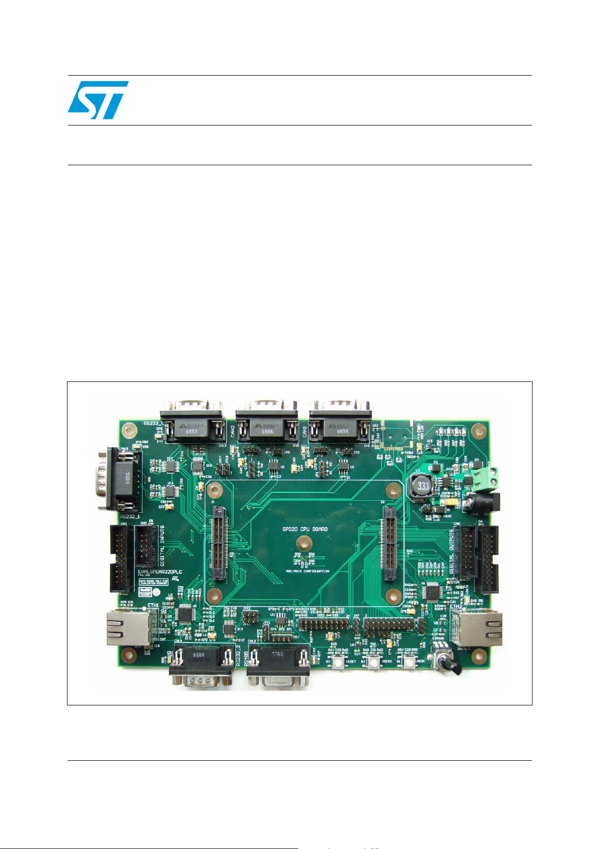
1 Description
This evaluation board can be used to evaluate the SPEAr320S microprocessor with a
variety of devices and especially its Media Independent Interface (MII) Automation mode.
The EVALSP320SPLC evaluation kit includes a single application board identified as "MII
mode".
The SPEAr320S microprocessor is mounted on a separate CPU board, which is not
included with the EVALSP320SPLC kit. It must be ordered separately with order code
EVALSP320SCPU.
The EVALSP320SCPU board must be plugged on the MII mode application board.
The MII mode application board is equipped with two Ethernet, three RS-232, one RS-485,
two CAN, SPI, I2C communication interfaces and MicroSD card socket with SDIO interface.
There are also two general-purpose push-buttons, four LEDs, a temperature sensor and a
potentiometer available for the user interface.
The application board also includes digital input/output serial/parallel connectors with a
pinout compatible to many existing evaluation boards from ST.
The application board can be powered using a standard DC power supply (7 V to 30 V DC)
or directly using a 24 V DC industrial mains supply.
2/4 Doc ID 023093 Rev 1
EVALSP320SPLC Revision history
2 Revision history
Table 1. Document revision history
Date Revision Changes
12-Apr-2012 1 Initial release.
Doc ID 023093 Rev 1 3/4

EVALSP320SPLC
Please Read Carefully:
Information in this document is provided solely in connection with ST products. STMicroelectronics NV and its subsidiaries (“ST”) reserve the
right to make changes, corrections, modifications or improvements, to this document, and the products and services described herein at any
time, without notice.
All ST products are sold pursuant to ST’s terms and conditions of sale.
Purchasers are solely responsible for the choice, selection and use of the ST products and services described herein, and ST assumes no
liability whatsoever relating to the choice, selection or use of the ST products and services described herein.
No license, express or implied, by estoppel or otherwise, to any intellectual property rights is granted under this document. If any part of this
document refers to any third party products or services it shall not be deemed a license grant by ST for the use of such third party products
or services, or any intellectual property contained therein or considered as a warranty covering the use in any manner whatsoever of such
third party products or services or any intellectual property contained therein.
UNLESS OTHERWISE SET FORTH IN ST’S TERMS AND CONDITIONS OF SALE ST DISCLAIMS ANY EXPRESS OR IMPLIED
WARRANTY WITH RESPECT TO THE USE AND/OR SALE OF ST PRODUCTS INCLUDING WITHOUT LIMITATION IMPLIED
WARRANTIES OF MERCHANTABILITY, FITNESS FOR A PARTICULAR PURPOSE (AND THEIR EQUIVALENTS UNDER THE LAWS
OF ANY JURISDICTION), OR INFRINGEMENT OF ANY PATENT, COPYRIGHT OR OTHER INTELLECTUAL PROPERTY RIGHT.
UNLESS EXPRESSLY APPROVED IN WRITING BY TWO AUTHORIZED ST REPRESENTATIVES, ST PRODUCTS ARE NOT
RECOMMENDED, AUTHORIZED OR WARRANTED FOR USE IN MILITARY, AIR CRAFT, SPACE, LIFE SAVING, OR LIFE SUSTAINING
APPLICATIONS, NOR IN PRODUCTS OR SYSTEMS WHERE FAILURE OR MALFUNCTION MAY RESULT IN PERSONAL INJURY,
DEATH, OR SEVERE PROPERTY OR ENVIRONMENTAL DAMAGE. ST PRODUCTS WHICH ARE NOT SPECIFIED AS "AUTOMOTIVE
GRADE" MAY ONLY BE USED IN AUTOMOTIVE APPLICATIONS AT USER’S OWN RISK.
Resale of ST products with provisions different from the statements and/or technical features set forth in this document shall immediately void
any warranty granted by ST for the ST product or service described herein and shall not create or extend in any manner whatsoever, any
liability of ST.
ST and the ST logo are trademarks or registered trademarks of ST in various countries.
Information in this document supersedes and replaces all information previously supplied.
The ST logo is a registered trademark of STMicroelectronics. All other names are the property of their respective owners.
© 2012 STMicroelectronics - All rights reserved
STMicroelectronics group of companies
Australia - Belgium - Brazil - Canada - China - Czech Republic - Finland - France - Germany - Hong Kong - India - Israel - Italy - Japan -
Malaysia - Malta - Morocco - Philippines - Singapore - Spain - Sweden - Switzerland - United Kingdom - United States of America
www.st.com
4/4 Doc ID 023093 Rev 1
 Loading...