

Page 1

UM1585
User manual
EVALSP1310CPU
evaluation board, hardware revision 1
Introduction
This document applies to hardware revision 1 evaluation boards.
This evaluation board is intended to be used to:
● enable quick evaluation and debugging of software for the SPEAr1310 rev.C embedded
MPU family
● act as a learning tool for rapid familiarity with the features of the SPEAr1310 rev.C
● provide a reference design to use as a starting point for the development of a final
application board
The EVALSP1310CPU board is equipped with interfaces to the high speed peripherals
embedded in SPEAr1310 rev. C devices.
Through an expansion connector it is possible to plug in dedicated expansion boards
(EVALBASEXP) and/or FPGA boards (EVALSP13xxFPGA) for developing customerspecific IPs.
Figure 1. EVALSP1310CPU board rev. 1
November 2012 Doc ID 023872 Rev 1 1/36
www.st.com
Page 2

Contents UM1585
Contents
1 Kit contents . . . . . . . . . . . . . . . . . . . . . . . . . . . . . . . . . . . . . . . . . . . . . . . . 6
2 Features and block diagram . . . . . . . . . . . . . . . . . . . . . . . . . . . . . . . . . . . 7
2.1 Board features . . . . . . . . . . . . . . . . . . . . . . . . . . . . . . . . . . . . . . . . . . . . . . 7
2.2 Connectors, jumpers and pushbuttons . . . . . . . . . . . . . . . . . . . . . . . . . . . . 8
3 Getting started . . . . . . . . . . . . . . . . . . . . . . . . . . . . . . . . . . . . . . . . . . . . . . 9
3.1 Connecting . . . . . . . . . . . . . . . . . . . . . . . . . . . . . . . . . . . . . . . . . . . . . . . . . 9
3.2 Booting . . . . . . . . . . . . . . . . . . . . . . . . . . . . . . . . . . . . . . . . . . . . . . . . . . . . 9
3.3 Serial interface . . . . . . . . . . . . . . . . . . . . . . . . . . . . . . . . . . . . . . . . . . . . . . 9
3.4 Reset switch . . . . . . . . . . . . . . . . . . . . . . . . . . . . . . . . . . . . . . . . . . . . . . . 10
4 Block descriptions . . . . . . . . . . . . . . . . . . . . . . . . . . . . . . . . . . . . . . . . . 11
4.1 General power supply . . . . . . . . . . . . . . . . . . . . . . . . . . . . . . . . . . . . . . . 11
4.1.1 Power LEDs . . . . . . . . . . . . . . . . . . . . . . . . . . . . . . . . . . . . . . . . . . . . . . 12
4.2 Dynamic memory subsystem . . . . . . . . . . . . . . . . . . . . . . . . . . . . . . . . . . 12
4.3 Static memory subsystem . . . . . . . . . . . . . . . . . . . . . . . . . . . . . . . . . . . . 13
4.3.1 Serial Flash . . . . . . . . . . . . . . . . . . . . . . . . . . . . . . . . . . . . . . . . . . . . . . 13
4.3.2 NAND Flash . . . . . . . . . . . . . . . . . . . . . . . . . . . . . . . . . . . . . . . . . . . . . . 13
4.3.3 NAND Flash expansion . . . . . . . . . . . . . . . . . . . . . . . . . . . . . . . . . . . . . 13
4.4 PCIe/SATA . . . . . . . . . . . . . . . . . . . . . . . . . . . . . . . . . . . . . . . . . . . . . . . . 14
4.4.1 PCIe clock . . . . . . . . . . . . . . . . . . . . . . . . . . . . . . . . . . . . . . . . . . . . . . . 14
4.5 Ethernet subsystem . . . . . . . . . . . . . . . . . . . . . . . . . . . . . . . . . . . . . . . . . 15
4.5.1 Configuration jumpers and switches . . . . . . . . . . . . . . . . . . . . . . . . . . . 15
4.5.2 Ethernet LEDs . . . . . . . . . . . . . . . . . . . . . . . . . . . . . . . . . . . . . . . . . . . . 18
5 USB 2.0 subsystem . . . . . . . . . . . . . . . . . . . . . . . . . . . . . . . . . . . . . . . . . 19
5.1 Host ports . . . . . . . . . . . . . . . . . . . . . . . . . . . . . . . . . . . . . . . . . . . . . . . . . 19
5.2 Host LEDs . . . . . . . . . . . . . . . . . . . . . . . . . . . . . . . . . . . . . . . . . . . . . . . . 19
5.3 OTG USB . . . . . . . . . . . . . . . . . . . . . . . . . . . . . . . . . . . . . . . . . . . . . . . . . 19
5.3.1 SPEAr USB interface power . . . . . . . . . . . . . . . . . . . . . . . . . . . . . . . . . 19
6 A/D Interface . . . . . . . . . . . . . . . . . . . . . . . . . . . . . . . . . . . . . . . . . . . . . . 21
2/36 Doc ID 023872 Rev 1
Page 3

UM1585 Contents
7 RTC (battery connector) . . . . . . . . . . . . . . . . . . . . . . . . . . . . . . . . . . . . . 21
8 Expansion connectors . . . . . . . . . . . . . . . . . . . . . . . . . . . . . . . . . . . . . . 22
9 Debug interface . . . . . . . . . . . . . . . . . . . . . . . . . . . . . . . . . . . . . . . . . . . . 24
10 Strapping options . . . . . . . . . . . . . . . . . . . . . . . . . . . . . . . . . . . . . . . . . . 25
11 Test modes . . . . . . . . . . . . . . . . . . . . . . . . . . . . . . . . . . . . . . . . . . . . . . . . 26
12 LEDs . . . . . . . . . . . . . . . . . . . . . . . . . . . . . . . . . . . . . . . . . . . . . . . . . . . . . 27
13 Jumper descriptions . . . . . . . . . . . . . . . . . . . . . . . . . . . . . . . . . . . . . . . . 28
14 Connectors . . . . . . . . . . . . . . . . . . . . . . . . . . . . . . . . . . . . . . . . . . . . . . . 29
15 Pushbuttons . . . . . . . . . . . . . . . . . . . . . . . . . . . . . . . . . . . . . . . . . . . . . . 29
Appendix A Licence agreements . . . . . . . . . . . . . . . . . . . . . . . . . . . . . . . . . . . . . 30
Revision history . . . . . . . . . . . . . . . . . . . . . . . . . . . . . . . . . . . . . . . . . . . . . . . . . . . . 35
Doc ID 023872 Rev 1 3/36
Page 4

List of figures UM1585
List of figures
Figure 1. EVALSP1310CPU board rev. 1 . . . . . . . . . . . . . . . . . . . . . . . . . . . . . . . . . . . . . . . . . . . . . . 1
Figure 2. Block diagram . . . . . . . . . . . . . . . . . . . . . . . . . . . . . . . . . . . . . . . . . . . . . . . . . . . . . . . . . . . . 7
Figure 3. Connector, jumper and push button locations (top) . . . . . . . . . . . . . . . . . . . . . . . . . . . . . . . 8
Figure 4. Serial cable setting (J17) . . . . . . . . . . . . . . . . . . . . . . . . . . . . . . . . . . . . . . . . . . . . . . . . . . 10
Figure 5. Serial Flash M25P64 (U1) and M25P40 (U3) enable . . . . . . . . . . . . . . . . . . . . . . . . . . . . . 13
Figure 6. NAND Flash selection. . . . . . . . . . . . . . . . . . . . . . . . . . . . . . . . . . . . . . . . . . . . . . . . . . . . . 13
Figure 7. NAND Flash device voltage selector . . . . . . . . . . . . . . . . . . . . . . . . . . . . . . . . . . . . . . . . . 14
Figure 8. SPEAr NAND Flash I/O voltage selector . . . . . . . . . . . . . . . . . . . . . . . . . . . . . . . . . . . . . . 14
Figure 9. SPEAr MIPHY PLL power selectors . . . . . . . . . . . . . . . . . . . . . . . . . . . . . . . . . . . . . . . . . . 14
Figure 10. SPEAr GMII I/F voltage selector . . . . . . . . . . . . . . . . . . . . . . . . . . . . . . . . . . . . . . . . . . . . . 16
Figure 11. Gigabit PHY Ethernet voltage selector . . . . . . . . . . . . . . . . . . . . . . . . . . . . . . . . . . . . . . . . 16
Figure 12. DP83865 clock output selector . . . . . . . . . . . . . . . . . . . . . . . . . . . . . . . . . . . . . . . . . . . . . . 17
Figure 13. SPEAr USB phy power selector . . . . . . . . . . . . . . . . . . . . . . . . . . . . . . . . . . . . . . . . . . . . . 20
Figure 14. Samtec connector. . . . . . . . . . . . . . . . . . . . . . . . . . . . . . . . . . . . . . . . . . . . . . . . . . . . . . . . 22
4/36 Doc ID 023872 Rev 1
Page 5

UM1585 List of tables
List of tables
Table 1. Common power rails . . . . . . . . . . . . . . . . . . . . . . . . . . . . . . . . . . . . . . . . . . . . . . . . . . . . . . 11
Table 2. Power LEDs . . . . . . . . . . . . . . . . . . . . . . . . . . . . . . . . . . . . . . . . . . . . . . . . . . . . . . . . . . . . 12
Table 3. J1 NAND expansion connector pin assignment . . . . . . . . . . . . . . . . . . . . . . . . . . . . . . . . . 13
Table 4. PCIe clock settings (default settings) . . . . . . . . . . . . . . . . . . . . . . . . . . . . . . . . . . . . . . . . . 15
Table 5. Switch 1 configuration. . . . . . . . . . . . . . . . . . . . . . . . . . . . . . . . . . . . . . . . . . . . . . . . . . . . . 15
Table 6. Jumper configurations . . . . . . . . . . . . . . . . . . . . . . . . . . . . . . . . . . . . . . . . . . . . . . . . . . . . 16
Table 7. DP83865, MAC interface setting . . . . . . . . . . . . . . . . . . . . . . . . . . . . . . . . . . . . . . . . . . . . 17
Table 8. Auto-negotiation disabled . . . . . . . . . . . . . . . . . . . . . . . . . . . . . . . . . . . . . . . . . . . . . . . . . . 17
Table 9. Auto-negotiation enabled . . . . . . . . . . . . . . . . . . . . . . . . . . . . . . . . . . . . . . . . . . . . . . . . . . 17
Table 10. Ethernet LEDs . . . . . . . . . . . . . . . . . . . . . . . . . . . . . . . . . . . . . . . . . . . . . . . . . . . . . . . . . . 18
Table 11. USB host LEDs . . . . . . . . . . . . . . . . . . . . . . . . . . . . . . . . . . . . . . . . . . . . . . . . . . . . . . . . . . 19
Table 12. OTG micro USB-AB LEDs . . . . . . . . . . . . . . . . . . . . . . . . . . . . . . . . . . . . . . . . . . . . . . . . . 19
Table 13. J14 (20) ADC connector A2D . . . . . . . . . . . . . . . . . . . . . . . . . . . . . . . . . . . . . . . . . . . . . . . 21
Table 14. Expansion connector functions - EXPI mode enabled . . . . . . . . . . . . . . . . . . . . . . . . . . . . 22
Table 15. Expansion connector functions - EXPI mode not enabled . . . . . . . . . . . . . . . . . . . . . . . . . 23
Table 16. J15 JTAG connector pin-out . . . . . . . . . . . . . . . . . . . . . . . . . . . . . . . . . . . . . . . . . . . . . . . . 24
Table 17. Debug mode selection . . . . . . . . . . . . . . . . . . . . . . . . . . . . . . . . . . . . . . . . . . . . . . . . . . . . 24
Table 18. Switch 3 (SW3) configuration . . . . . . . . . . . . . . . . . . . . . . . . . . . . . . . . . . . . . . . . . . . . . . . 25
Table 19. Switch 4 (SW4) configuration . . . . . . . . . . . . . . . . . . . . . . . . . . . . . . . . . . . . . . . . . . . . . . . 25
Table 20. Software boot options . . . . . . . . . . . . . . . . . . . . . . . . . . . . . . . . . . . . . . . . . . . . . . . . . . . . . 25
Table 21. Test modes . . . . . . . . . . . . . . . . . . . . . . . . . . . . . . . . . . . . . . . . . . . . . . . . . . . . . . . . . . . . . 26
Table 22. Status LEDs . . . . . . . . . . . . . . . . . . . . . . . . . . . . . . . . . . . . . . . . . . . . . . . . . . . . . . . . . . . . 27
Table 23. List of board jumpers . . . . . . . . . . . . . . . . . . . . . . . . . . . . . . . . . . . . . . . . . . . . . . . . . . . . . 28
Table 24. List of board connectors . . . . . . . . . . . . . . . . . . . . . . . . . . . . . . . . . . . . . . . . . . . . . . . . . . . 29
Table 25. Document revision history . . . . . . . . . . . . . . . . . . . . . . . . . . . . . . . . . . . . . . . . . . . . . . . . . 35
Doc ID 023872 Rev 1 5/36
Page 6

Kit contents UM1585
1 Kit contents
● EVALSP1310CPU board
● AC adapter (output voltage 5 V 2A)
● 2 power adapter plugs (USA/Europe)
6/36 Doc ID 023872 Rev 1
Page 7

UM1585 Features and block diagram
Trace
debug
NOR
Flash
SPEAr1310
NOR
Flash
NAND
Flash 8-bit
JTAG
debug
Trace
debug
UART
A2D 8 channels
NAND Flash
exp. Conn.
8/16-bit
Core
power
supply
Power combo
PM6641 (3V3,
2V5, 1V5)
ETH PHY
10/100/
1000
ETH
connector
USB 2.0
Host 1&2
USB OTG
SATA
PCIe root
complex
PCIe end
point
DDR3
DDR3
DDR3
DDR3
DDR3
FSMC-LCD-MAC
Expansion connector
2 Features and block diagram
2.1 Board features
● SPEAr1310 SoC CPU
● Dedicated 16/32-bit trace port (program trace)
● Five DDR3 chips (32-bit width plus ECC), 1 GB
● Serial NOR Flash, 8 MB
● Serial NOR Flash 512 KB
● 8-bit NAND Flash, 256 MB
● 16-bit NAND Flash expansion connector
● Two USB 2.0 full speed Host ports
● One OTG 2.0 high speed port (Micro USB-AB)
● One 10/100/1000 Ethernet port
● One SATA connector
● One PCIe X1 Endpoint
● One PCIe X1 Root Complex connector
● One Serial port (up to 115 Kbaud)
● Debug ports (CPU JTAG & CoreSight)
● 8 ADC channels (10 bit, 1 Msamples/s)
● Expansion connector
Figure 2. Block diagram
Doc ID 023872 Rev 1 7/36
Page 8

Features and block diagram UM1585
2.2 Connectors, jumpers and pushbuttons
Figure 3. Connector, jumper and push button locations (top)
8/36 Doc ID 023872 Rev 1
Page 9

UM1585 Getting started
3 Getting started
Caution: This board contains electrostatic-sensitive devices
The EVALSP1310CPU board is shipped in protective anti-static packaging. Do not submit
the board to high electrostatic potentials, and follow good practices for working with static
sensitive devices.
● Wear an anti-static wristband. Wearing a simple anti-static wristband can help to
prevent ESD from damaging the board.
● Zero potential. Always touch a grounded conducting material before handling the
board, and periodically while handling it.
● Use an anti-static mat. When configuring the board, place it on an anti-static mat to
reduce the possibility of ESD damage.
● Handle only the edges. Handle the board by its edges only, and avoid touching board
components.
3.1 Connecting
1. Connect a serial cable adapter (RS232 on J16) to a host PC (see Primary Serial cable
setting).
2. On a host PC running Windows or Linux, start the Terminal program.
3. Connect the AC adapter to a power outlet.
4. Power on the board (plug the AC adapter jack into J12). A sequence of boot messages
displays, followed by the Linux console prompt.
Software user manuals are available on request; contact your local ST representative.
3.2 Booting
The EVALSP1310CPU board can boot a Linux kernel pre-installed in the serial NOR Flash.
At power on, the serial port outputs a brief header message with some uBoot information
(uBoot version, SDK version, and some internal hardware information). At this point, you
can choose to:
● Stop the system directly in uBoot
To do this, press the spacebar on the host computer keyboard before the boot delay
time expires (default is 3 seconds).
● Boot Linux
The system logs you in automatically as super user, and the Linux shell prompt
displays on the screen.
3.3 Serial interface
A serial interface, which can typically be used to connect an operating system monitor
console, is available on the J16 connector.
Doc ID 023872 Rev 1 9/36
Page 10

Getting started UM1585
Cross
cable
J17
12
34
J17
12
34
modem
cable
Null
It is possible to simulate a cross cable by changing the position of the J17 jumpers as shown
below.
Refer to the schematic drawing (contact your local ST representative for availability), for the
pin-out of the connectors.
Figure 4. Serial cable setting (J17)
3.4 Reset switch
A manual reset switch (P1) is available on the top side of the board.
10/36 Doc ID 023872 Rev 1
Page 11

UM1585 Block descriptions
4 Block descriptions
4.1 General power supply
The power supply block generates all the required voltages from a 5 V external AC/DC. The
generated voltages are:
● 5 V obtained from an over voltage protection device with thermal shutdown
● 1.2 V, generated from 5 V with a step-down switching regulator
● 1.5 V, 2.5 V, and 3.3 V generated from 5 V with a multi-output switching regulator
● 12 V generated from 5 V with a set-up converter
● 1.8 V generated from 3.3 V with a low drop voltage regulator
Table 1. Common power rails
Jumper
Name Use
for current
measurement
+5V
VDD1V2
VDD1V5
VDD1V8
VDD2V5
VDD3V3
J13: Alternate power input connector
J11: Expansion connector
SPEAr core (SPEAr_VDD1V2)
SPEAr DDR3 interface (SPEAr_DDR3_1V2)
DDR3 chips
SPEAr DDR I/O (SPEAr_DDR3_1V5)
SPEAr RTC (RTC_VDD1V5)
GigaPhy chip
SPEAr 1.8 V NAND8 Flash (JP3: Close 2&3 for 1.8 V)
NAND Flash chip (Close 2&3 of JP2 for 1.8V)
NAND expansion connector (Close2&3 of JP3)
SPEAr_OTP antifuses (JP1: Close 1&2 to supply)
SPEAr GMII interface(JP16: Close 2&3 for 2.5V)
SPEAr PCIe (JP24 close and JP5: Close 2&3 for ext power)
SPEAr A2D_PLLs_VDD2V5
SPEAr USB_VDD2V5
A2D connector
Ethernet RJ45 (J2)
Giga PHY (JP42 close 2&3)
SPEAr (SPEAr_VDD3V3)
PCIe Clock Source
JTAG MIPHY connector
Giga PHY (JP42 close 1&2)
Serial NOR Flash
NAND Flash chip (Close 1&2 of JP2 for 3.3V)
NAND expansion connector (Close1&2 of JP3)
CPU JTAG & trace connectors
JP31
JP30
JP32
JP39
-
JP3(2-3)
JP33
JP1(1-2)
JP16(2-3)
JP34
Doc ID 023872 Rev 1 11/36
Page 12

Block descriptions UM1585
Table 1. Common power rails (continued)
Jumper
Name Use
VDD3V3_HOST PCIe x1 connectors
+12V_HOST PCIe x1 connectors
for current
measurement
4.1.1 Power LEDs
Table 2. Power LEDs
Ref. Des. Description
D11 red 5 volt fault: undervoltage or overvoltage on +5V
D13 green 5 volt: +5V
D12 green 1.2 volt: VDD1V2
D14 green 1.5 volt: VDD1V5
D17green 1.8 volt: VDD1V8
D16 green 2.5 volt: VDD2V5
D15 green 3.3 volt: VDD3V3
A low-power supervisory device monitors the power supplies and generates a reset signal.
4.2 Dynamic memory subsystem
Five Micron DDR3 chips (MT41J256M8) are used: four for data (32-bit width), and one for
ECC.
Total size available is 4 chips x 32 Mb x 8 x 8 banks = 1 Gbyte.
12/36 Doc ID 023872 Rev 1
Page 13
UM1585 Block descriptions
J23
12
34
J23
12
34
SMI_CS0n
U3 enableU1 enable
SMI_CS0n
JP4
12
U4
deselected
J4
12
U4
selected
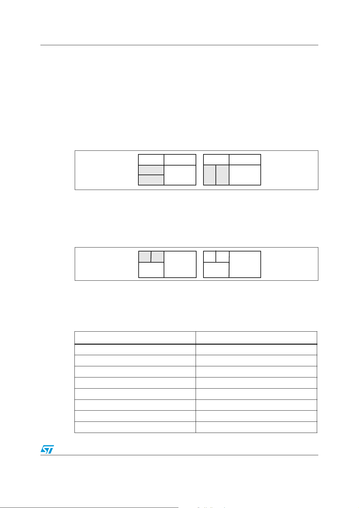
4.3 Static memory subsystem
4.3.1 Serial Flash
The following components are connected to the SMI interface:
● M25P64 (U1) ST serial Flash device: memory size = 8 MB
● M25P40 (U3) ST serial Flash device: memory size = 512 KB (optional, the device is not
installed on the board)
To enable M25P64 or M25P40, use SMI_CS0 with the J23 jumpers set as shown in
Figure 5.
Figure 5. Serial Flash M25P64 (U1) and M25P40 (U3) enable
4.3.2 NAND Flash
This block is based on ST NAND Flash NAND02GW3B (U4) (64 MB; bus width = x8). If
required, this chip can be replaced and another can be used. To do this, deselect the onboard Flash by removing jumper JP4, and connect an adapter board to J1.
Figure 6. NAND Flash selection
4.3.3 NAND Flash expansion
A 30-pin expansion connector (J1) enables the use of different Flash devices. When used,
remove jumper JP4.
Table 3. J1 NAND expansion connector pin assignment
Pin number Signal
1, 3, 29 NAND_VDD
2, 4, 28, 30 GND
5 ... 20 NFIO0 ... NFIO15
21 NFnCE
22 NFALE
23 NFCLE
24 NFRnB
25 NFnRE
Doc ID 023872 Rev 1 13/36
Page 14

Block descriptions UM1585
JP2
1
3
3.3 V
2
JP2
1
3
2
1.8 V
JP3
1
3
3.3 V
2
JP3
1
3
1.8 V
2
JP24
12
External
(closed)
JP5
1
3
External
2
JP5
1
3
Internal
2
JP24
12
Internal
(closed)
Table 3. J1 NAND expansion connector pin assignment (continued)
26 NFnWP
27 NFnWE
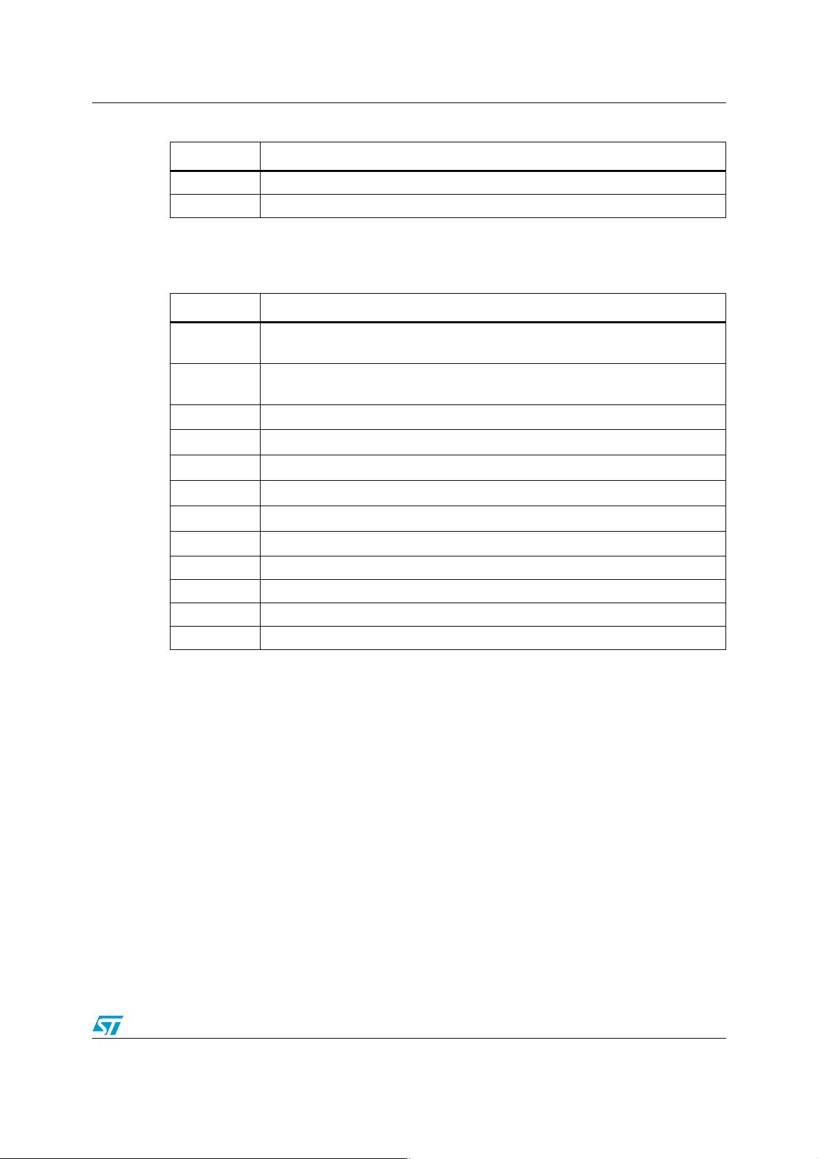
On the expansion connectors it is possible, through JP2, to select NAND_VDD between
3.3 V and 1.8 V to test different voltage devices. The NAND FLASH SPEAr I/O voltage has
to be aligned with the Flash device voltage. Use JP2, JP3 and Strapping option SW4.1 to
set the correct voltage.
Figure 7. NAND Flash device voltage selector
Figure 8. SPEAr NAND Flash I/O voltage selector
4.4 PCIe/SATA
The SPEAr1310 rev. C device has up to 3 PCIe or 3 SATA interfaces. The
EVALSP1310CPU board provides the following configuration: one standard SATA and two
PCIe Gen2 lanes.
The lane (PHY1) is used as a PCIe endpoint. In the default setting, the PCIe endpoint is not
available. To make the PCIe endpoint available it is necessary to change the settings of the
board removing the 0 ohm resistors, R90 and R91 and installing 0 ohm resistors, R92 and
R93. The lane PHY0 is used as SATA and on board there is a standard connector (J3).
SPEAr MIPHY PLL can be powered by an internal regulator or can use external power.
JP24 has to be configured according to the JP5 setting.
Figure 9. SPEAr MIPHY PLL power selectors
4.4.1 PCIe clock
The PCIe clock is generated by ICS557-03 (differential clock generator). This device can
generate 2 different clock frequencies. This depends on the settings of bits S2 to S0.
14/36 Doc ID 023872 Rev 1
Page 15

UM1585 Block descriptions
Table 4. PCIe clock settings (default settings)
S2 (SW2-3) S1(SW2-2) S0 (SW2-1) Spread % Spread type Output frequency
0 0 0 -0.5 Down 100
0 0 1 -1.0 Down 100
0 1 0 -1.5 Down 100
0 1 1 No spread Not applicable 100
1 0 0 -0.5 Down 200
1 0 1 -1.0 Down 200
1 1 0 -1.5 Down 200
1 1 1 No spread Not applicable 200
The output frequency must be set at 100 MHz. On the EVALSP1310CPU board, the default
settings is S2 ... S0 = 0.
4.5 Ethernet subsystem
This subsystem is based on the Ethernet GMII PHY DP83865 (U5) and a connector that
also includes all the required magnetics. Several configuration jumpers are present and also
several LEDs to display the line status/activity.
4.5.1 Configuration jumpers and switches
Table 5. Switch 1 configuration
Pin Description (default settings)
1 Phy address bit 1 (0 - ON)
2 Phy address bit 2 (1 - OFF)
3 Phy address bit 3 (0 - ON)
4 Phy address bit 4 (0 - ON)
MULTIPLE NODE ENABLE: This pin determines if the PHY advertises Master (multiple
nodes) or Slave (single node) priority during 1000BASE-T Auto-Negotiation.
5
1: multiple node priority (switch or hub)
0: single node priority (NIC) (0 - ON)
AUTO MDIX ENABLE: This pin controls the automatic pair swap (Auto-MDIX) of the
MDI/MDIX interface.
6
1: pair swap mode enabled
0: Auto-MDIX disabled, and part defaulted into the mode preset by the
MAN_MDIX_STRAP pin. (0 - ON)
CLOCK TO MAC ENABLE:
7
1: CLK_TO_MAC clock output enabled
0: CLK_TO_MAC disabled (1 - OFF)
8 Not used
Doc ID 023872 Rev 1 15/36
Page 16

Block descriptions UM1585
JP16
12
3
3.3 V
JP16
12
3
2.5 V
JP42
12
3
3.3 V
JP42
12
3
2.5 V
Note: When DIP switch SWx-x is in the ON position, the bit value is 0. When the DIP switch is in
the OFF position, the bit value is 1.
Table 6. Jumper configurations
Default Settings
Description
On Off
JP6 JP11
1 2312 3
JP7 JP12
1
2 3 1 23
JP8 JP13
1 2312 3
JP9 JP14
2 3 1 23
1
JP10 JP15
1 2312 3
Phy address bit 0
Auto negotiation enable bit
Full duplex select bit
Speed select bit 1 (see Table 3: J1 NAND expansion
connector pin assignment and Table 4: PCIe clock
settings (default settings))
Speed select bit 1 (see Table 3: J1 NAND expansion
connector pin assignment and Table 4: PCIe clock
settings (default settings))
SPEAr GMII I/F VDD could be 3.3 V or 2.5 V. It is possible test this functionality by moving
two jumpers: one for SPEAr pads and one for the external DP83865 (U5).
The two jumpers must also be aligned with strapping option SW4.2.
Figure 10. SPEAr GMII I/F voltage selector
Figure 11. Gigabit PHY Ethernet voltage selector
Three JP are used as DP83865 (U5) strapping option: JP17, JP18 and JP19.
16/36 Doc ID 023872 Rev 1
Page 17

UM1585 Block descriptions
JP17
12
3
1
JP17
12
3
0
0 = Clock to MAC output is 25 MHz
1= Clock to MAC output is 125 MHz
Figure 12. DP83865 clock output selector
Table 7. DP83865, MAC interface setting
JP18
(TXCLK_RGMII_SEL1)
(CRS_RGMII_SEL0)
JP19
00GMII
01GMII
10RGMII HP
1 1 RGMII 3COM
Note: EVALSP1310CPU BOARD was designed for GMII mode only.
SPEED SELECT STRAP: These strapping option pins have two different functions
depending on whether auto-negotiation is enabled or not. See Ta bl e 8 and Ta bl e 9 .
Table 8. Auto-negotiation disabled
Speed[1] Speed[0] Speed enabled
11 Reserved
1 0 1000BASE-T
0 1 100BASE-T
0 0 10BASE-T
Table 9. Auto-negotiation enabled
MAC Interface
Speed[1] Speed[0] Speed enabled
1 1 1000BASE-T, 10BASE-T
1 0 1000BASE-T
0 1 1000BASE-T, 100BASE-T
0 0 1000BASE-T, 100BASE-T, 10BASE-T
Doc ID 023872 Rev 1 17/36
Page 18

Block descriptions UM1585
4.5.2 Ethernet LEDs
Table 10. Ethernet LEDs
Reference Description
D1
Ye l l o w
D2
Ye l l o w
D3
Ye l l o w
D4
Ye l l o w
D5
Ye l l o w
DUPLEX STATUS: The LED is lit when the PHY is in Full Duplex operation after
the link is established.
1000M SPEED AND GOOD LINK LED: The LED output indicates that the PHY
has established a good link at 1000 Mbps.
In 1000BASE-T mode, the link is established as a result of training, AutoNegotiation completed, valid 1000BASE-T link established and reliable reception
of signals transmitted from a remote PHY is received.
100M SPEED AND GOOD LINK LED: The LED output indicates that the PHY
has established a good link at 100 Mbps.
In 100BASE-T mode, the link is established as a result of an input receive
amplitude compliant with TP-PMD specifications which will result in internal
generation of Signal Detect. LINK100_LED will assert after the internal Signal
Detect has remained asserted for a minimum of 500 µs. LINK100_LED will deassert immediately following the de-assertion of the internal Signal Detect.
10M GOOD LINK LED: In the standard 5-LED display mode, this LED output
indicates that the PHY has established a good link at 10 Mbps.
ACTIVITY LED: The LED output indicates the occurrence of either idle error or
packet transfer.
18/36 Doc ID 023872 Rev 1
Page 19

UM1585 USB 2.0 subsystem
5 USB 2.0 subsystem
5.1 Host ports
The board has two host ports that are fully compliant with the USB 2.0 specification (two
controllers with one port each). This means that the two hosts can work in concurrent mode
with the maximum possible bandwidth. Each host has also full control of the VBUS supplied
by the ST2052 or STMP2252MTR power switch that also provides over current protection in
case of a short circuit in the USB cable. The ports are equipped with LEDs showing the
power status of each port (the green LED indicates the presence of VBUS and the red one
the current limiter status).
5.2 Host LEDs
USB host LEDs
Table 11. USB host LEDs
Reference Description
D7
Red
D8
Green
D9
Green
D10
Red
USB HOST1 OVERCURRENT: Abnormal current flowing on USB HOST 1 port
USB HOST1 VBUS: VBUS present on USB HOST port 1
USB HOST1 VBUS: VBUS present on USB HOST port 2
USB HOST2 OVERCURRENT: Abnormal current flowing on USB HOST 2 port
5.3 OTG USB
One OTG micro USB-AB connector is present on the board.
Table 12. OTG micro USB-AB LEDs
Reference Description
D20 Red USB OTG OVERCURRENT: Abnormal current flowing on OTG USB
D19 Green USB OTG VBUS: VBUS present on OTG USB
5.3.1 SPEAr USB interface power
SPEAr USB phy (2.5 V) could be powered by an internal regulator or use external power.
Doc ID 023872 Rev 1 19/36
Page 20

USB 2.0 subsystem UM1585
JP29
12
3
Inter nal
JP29
12
3
External
Figure 13. SPEAr USB phy power selector
20/36 Doc ID 023872 Rev 1
Page 21

UM1585 A/D Interface
6 A/D Interface
Eight analog input lines are provided on the J14 strip connector.
Table 13. J14 (20) ADC connector A2D
Pin number Signal
1 ADC_VREFP
2 ADC_VDD2V5
3 ... 17 (odd only) AIN0 ... AIN7
4 ... 20 (even only) AGND
19 ADC_VREFN
The connector also allows you to determine the conversion range by setting the conversion
limits on pins J14.19 (lower limit) and J14.1 (upper limit). The default setting is to have pins
1-2 and 19-20 shorted by jumpers, which sets the conversion range to the maximum value
of 0 to 2.5 V, with a granularity of 2.44 mV.
Removing the two jumpers and providing different values on pins 1 and 19 makes it possible
to reduce the range, increasing the granularity. For example, an input of 1 V on J14.19 and 2
V on J14.1 provides a range of 1 to 2 V, in steps of less than 1 mV.
In any case, ensure the following relationships between the pins:
0 V ≤ J14.19 ≤ J14 17 .. 3 ≤ J14.1 ≤ +2.5 V
AGND ≤ Vref_n ≤ ADC_In channels ≤ Vref_p ≤ AVDD
7 RTC (battery connector)
To avoid losing data even if the main power supply is switched off, the Real Time Clock can
be powered with a 3 V external battery (J19).
Doc ID 023872 Rev 1 21/36
Page 22

Expansion connectors UM1585
8 Expansion connectors
Expansion connectors J11 and J21 are provided to enable the use of an additional board.
Both connectors are Samtec High Speed Board-to-Board connectors Q2 Right angle.
● J11, P/N QFS-104-01-SL-D-RA, mates with QMS-104-01-SL-D-RA
● J21, P/N QFS-026-01-SL-D-RA, mates with QMS-026-01-SL-D-RA
The signals available on the expansion connector are shown in Expansion connector
functions.
Figure 14. Samtec connector
Note: EXPI mode enabled/disabled (refer to Ta bl e 2 1 to configure EXPI mode).
Table 14. Expansion connector functions - EXPI mode enabled
Pin Description
4
8
33
2
5
4
30
10
22/36 Doc ID 023872 Rev 1
PLL_CLK1 ... 3
No function
MCI expansion 8 ... 15
NOR parallel Flash
SMI exp CS
Second LCD
Keypad expansion to 9x9
GPIO
UART modem expansion
(1)
Page 23
UM1585 Expansion connectors
Table 14. Expansion connector functions - EXPI mode enabled (continued)
Pin Description
1Timers
1I2S
1. Usable only with the addition of 15 FSMC signals. To make the 15 FSMC signals available, load resistors
R314 through R328, and remove jumper JP4.
Table 15. Expansion connector functions - EXPI mode not enabled
Pin Description
4
NAND Flash CE & WPRT
Keyboard expansion to 6x6
Keyboard 2x2
8
33
2
5
4
30
10
NAND Flash expansion 8 ... 15
MCI (memory card interface)
I2C
I2S
SPI
LCD
GPIO
1 FPGA done (input)
1 Reset
4ADC
2MAC I/F
Doc ID 023872 Rev 1 23/36
Page 24

Debug interface UM1585
9 Debug interface
The following debug interfaces are provided:
● The CPU JTAG interface: this can be used for "static" debug, meaning that it is
possible to set a breakpoint and, when the system stops, to verify the contents of the
memory and/or registers and modify them if needed.
Table 16. J15 JTAG connector pin-out
Pin number Signal
1, 2 VDD3V3
4 ... 20 GND
3nTRST
5TDI
7TMS
9TCK
13 TDO
15 Powergood
11,17,19 NC
● The PCIe JTAG interface: (reserved)
● The CPU coresight interface. (Trace 16 or 32) This can be used for "dynamic" debug.
The coresight block embedded in the SPEAr1310 chip sends all the information about
the AHB transactions during code execution to the external trace box and the external
box stores this information in a local buffer. This makes it possible to stop the CPU
activity in order to analyze the program flow. For example, if a particular data abort
occurs, you can set a breakpoint on the data abort location and then, when the
breakpoint is reached you can analyze the trace buffer. With this information, it
becomes a simple task to identify the event that produced the problem.
Table 17. Debug mode selection
Switch5
Description
321
0 0 0 No debug features available
0 0 1 The ARM JTAG is connected to J15
0 1 0 ARM Trace 16bit bus available on J18 and J20
0 1 1 ARM Trace 32bit bus available on J18 and J20
24/36 Doc ID 023872 Rev 1
Page 25

UM1585 Strapping options
10 Strapping options
General purpose I/Os are present on the board. They are connected to DIP switches to
allow the user to select/deselect them.
Immediately after reset phase, the SPEAr can be configured by means of the GPIO_A0 ...
A3 strapping options.
2 µs after reset, pins can be used with GPIO features.
Note: Important: To use pins as input, the external pin driver must be in tri-state for the duration of
the reset phase plus 2 µs.
Table 18. Switch 3 (SW3) configuration
Pin Description (default settings)
1 GPIO_A0 (OFF) (See Table 20: Software boot options for description)
2 GPIO_A1 (ON) (See Table 20: Software boot options for description)
3 GPIO_A2 (ON) (See Table 20: Software boot options for description)
4 GPIO_A3 (ON) (See Table 20: Software boot options for description)
8 Not used
Note: When DIP switch SWx-x is in the ON position, the bit value is 0. When the DIP switch is in
the OFF position, the bit value is 1.
Table 19. Switch 4 (SW4) configuration
Pin Description (default settings)
NAND Flash interface voltage (OFF)
1
2
3
4 Not used
Table 20. Software boot options
Bypass internal bootROM and jump to code in serial
NOR Flash (SMI interface)
OFF = 3.3 volt
ON = 1.8 volt
GMII interface 2.5 V (OFF)
OFF = 3.3 V
ON = 2.5 V
PCI level (to allow a PCI implementation in the SPEAr13x RAS) (OFF)
OFF = Normal level
ON = PCI level for PL_GPIO[86÷99] [6÷53]
Boot Type
SW3-4
GPIO_A3
SW3-3
GPIO_A2
SW3-2
GPIO_A1
0000
SW3-1
GPIO_A0
Boot from external serial NOR Flash (SMI).If the code
not valid, boot from USB is forced.
Doc ID 023872 Rev 1 25/36
0001
Page 26

Test modes UM1585
Table 20. Software boot options (continued)
Boot from external serial NAND Flash (FSMC). If the
code is invalid, boot from USB is forced.
Boot from external serial NOR Flash (FSMC). If the
code is invalid, boot from USB is forced.
Boot from I2C (device address). If the code is invalid,
boot from USB is forced.
Boot from UART
(115 baud, no parity, 8 data bits, 1 stop bit)
Note: Not available on engineering sample devices
(ES marking)
Boot from PCIe device 0110
Reserved 0111
Boot from USB device. (VID PID) 1000
11 Test modes
At reset, the SPEAr device can be configured in different modes through SW5.
Boot Type
SW3-4
GPIO_A3
0010
0011
0100
0101
SW3-3
GPIO_A2
SW3-2
GPIO_A1
SW3-1
GPIO_A0
In EXPI mode, the PL_GPIO0 ... 100 pins are mapped to the internal bus signals.
Table 21. Test modes
Boot Type
Functional: normal mode 0 0 0 0
CPU JTAG debug 0 0 0 1
CPU Trace 16 bits 0 0 1 0
CPU Trace 32 bits 0 0 1 1
EXPI mode 0 1 0 0
EXPI and CPU JTAG debug 0 1 0 1
EXPI and CPU Trace 16 bits 0 1 1 0
EXPI and CPU Trace 32 bits 0 1 1 1
Reserved configurations 1 x x x
SW5-4
TEST3
SW5-3
TEST2
SW5-2
TEST1
SW5-1
TEST0
26/36 Doc ID 023872 Rev 1
Page 27

UM1585 LEDs
12 LEDs
Several LEDs are present on the board. They display the following status information:
Table 22. Status LEDs
LED Color Status displayed
D1 Yellow GIG PHY Duplex
D2 Yellow GIG PHY link1000
D3 Yellow GIG PHY Link100
D4 Yellow GIG PHY Link10
D5 Yellow GIG PHY Activity
D7 Red Host1 Overcurrent
D8 Green USB Host1 5V
D9 Green USB Host2 5V
D10 Red USB Host2 Overcurrent
D11 Red
D12 Green VDD1V2
D13 Green +5V
Overvoltage or undervoltage protection activated (STBP120
pin 3)
D14 Green VDD1V5
D15 Green VDD3V3
D16 Green VDD2V5
D17 Green VDD1V8
Doc ID 023872 Rev 1 27/36
Page 28
Jumper descriptions UM1585
13 Jumper descriptions
The board has the following jumpers for settings or measurements:
Table 23. List of board jumpers
Jumper Description
J23 (4) M25P64 (U1) nCS select (default 1-2 closed: 3-4 closed)
JP1 (3) SAFHV antifuse (OTP) cell power supply VDD2V5 (default closed 1-2)
JP2 (3) NAND FLASH VDD (default 1-2 closed = 3.3 V)
JP3 (3) NAND FLASH SPEAr I/O (default 1-2 closed = 3.3 V)
JP4 (2) On-board NAND FLASH (U4) closed = enabled
JP5 (3) MIPHY (U5) VDD_IO (default 1-2 closed = 3.3 V)
JP6 - JP11 (3+3) GIGA PHY STRAP13
JP7 - JP12 (3+3) GIGA PHY STRAP10
JP8 - JP13 (3+3) GIGA PHY STRAP9
JP9 - JP14 (3+3) GIGA PHY STRAP8
JP10 - JP15 (3+3) GIGA PHY STRAP7
JP16 (3) SPEAr GMII I/F VDD (default 1-2 closed = 3.3 V)
JP17 (3) GMII_COL. (default 1-2 closed = pull up)
JP18 (3) MII_TXCLK_SEL1 (default 2-3 closed)
JP19 (3) CRS_RGMII_SEL0 (default 2-3 closed)
JP23 (2) Power OFF LM2731 (U7) (default open)
JP24 (2) Connect SPEAr_VDD2V5 to MIPHY_VDD2V5_PLL (default open)
JP27 (3) MIPHY_VDD1V2 (default 1-2 closed)
JP28 (3) A2D_PLL_VDD2.5 (default 1-2 closed = internal regulator)
JP29 (3) USB_VDD2V5. (default 1-2closed = internal regulator)
JP30 (2) SPEAr_DDR3_1V2 (default closed)
JP31 (2) SPEAr_VDD1V2 (default closed)
JP32 (2) SPEAr_DDR3_1V5 (default closed)
JP33 (2) SPEAr_VDD2V5 (default closed)
JP34 (2) SPEAr_VDD3V3 (default closed)
JP37 (2) SS_nINH, Power off L5989 (U21) (default open)
JP39 (2) RTC_VDD1V5 (default closed)
JP42 GIG PHY Ethernet power selection (default 1-2 closed = 3.3 V)
JP44 (3) RTC Power Selection (default 1-2 closed)
28/36 Doc ID 023872 Rev 1
Page 29

UM1585 Connectors
14 Connectors
Table 24. List of board connectors
Connector Description
J1 CON32A NAND
J2 RJ45 Ethernet connector
J3 SATA connector
J4 PCIe Root complex (HOST1)
J5 PCIe Endpoint (Device)
J6 +12 V_HOST (PCIe)
J7 MIPHY JTAG Connector
J8 USB Connector Micro A-B (OTG)
J10 USB Connector Type A double
J11 QFS-104-RA Expansion connector
J12 +5 V
J13 +5V
J14 ADC Connector A/D
J15 J15 (20) CPU JTAG
J16 J16 (10) UART
J17 RS232 invert RX<>TX
J18 (Mictor38) Core-sight
J19 Battery connector (1 positive, 2 gnd)
J20 (Mictor38) Core-sight
J21 QFS-026-RA Expansion connector
J22 UART TX and RX probing
15 Pushbuttons
P1 Reset switch (pin 3) STM811 (U16)
P2 Wakeup switch GPIO 7
Doc ID 023872 Rev 1 29/36
Page 30

Licence agreements UM1585
Appendix A Licence agreements
DEMO PRODUCT LICENSE AGREEMENT
By using this Demonstration Product, You are agreeing to be bound by the terms and conditions of this agreement.
Do not use this Demonstration Product until You have read and agreed to the following terms and conditions. The
use of the Demonstration Product implies automatically the acceptance of the following terms and conditions.
LICENSE. STMicroelectronics ("ST") grants You the right to use the enclosed demonstration board offering limited features
only to evaluate and test ST products, including any incorporated and/or accompanying demo software, components and
documentation identified with the order code "SPEAr1310" (collectively, the "Demo Product") solely only for your evaluation
and testing purposes. The Demo Product shall not be, in any case, directly or indirectly assembled as a part in any
production of Yours as it is solely developed to serve demonstration purposes and has no direct function and is not a finished
product. Certain demo software included with the Demo Product may be covered under a separate accompanying end user
license agreement, in which case the terms and conditions of such end user license agreement shall apply to that
demonstration software.
DEMO PRODUCT STATUS. The Demo Product is offering limited features allowing You only to evaluate and test the ST
products. You are not authorized to use the Demo Product in any production system, and may not be offered for sale or
lease, or sold, leased or otherwise distributed. If the Demo Product is incorporated in a demonstration system, the
demonstration system may be used by You solely for your evaluation and testing purposes. Such demonstration system
may not be offered for sale or lease or sold, leased or otherwise distributed and must be accompanied by a conspicuous
notice as follows: "This device is not, and may not be, offered for sale or lease, or sold or leased or otherwise distributed".
OWNERSHIP AND COPYRIGHT. Title to the Demo Product, demo software, related documentation and all copies thereof
remain with ST and/or its licensors. You may not remove the copyrights notices from the Demo Product. You may make one
(1) copy of the software for back-up or archival purposes provided that You reproduce and apply to such copy any copyright
or other proprietary rights notices included on or embedded in the demonstration software. You agree to prevent any
unauthorized copying of the Demo Product, demonstration software and related documentation.
RESTRICTIONS. You may not sell, assign, sublicense, lease, rent or otherwise distribute the Demo Product for commercial
purposes (unless you are an authorized ST distributor provided that all the other clauses of this DEMO
PRODUCT LICENSE AGREEMENT shall apply entirely), in whole or in part, or use Demo Product in production system.
Except as provided in this Agreement or in the Demo Product's documentation, You may not reproduce the demonstration
software or related documentation, or modify, reverse engineer, de-compile or disassemble the demonstration software, in
whole or in part.
You warrant to ST that the Demo Product will be used and managed solely and exclusively in a laboratory by skilled
professional employees of Yours with proven expertise in the use and management of such products and that the
Demo Product shall be used and managed according to the terms and conditions set forth in the related
documentation provided with the Demo Product.
According to European Semiconductor Industry Association (ESIA) letter, "ESIA Response on WEEE Review (May
2008) of the Directive 2002/96/EC on Waste Electrical and Electronic Equipment (WEEE)"; Semiconductor products
and evaluation & demonstration boards are not in the scope of the Directive 2002/96/EC of the European Parliament
and of the Council on waste electrical and electronic equipment (WEEE). Consequently aforementioned products
do not have to be registered nor are they subject to the subsequent obligations.
NO WARRANTY. The Demo Product is provided "as is" and "with all faults" without warranty of any kind expressed or
implied. ST and its licensors expressly disclaim all warranties, expressed, implied or otherwise, including without limitation,
warranties of merchantability, fitness for a particular purpose and non-infringement of intellectual property rights. ST does
not warrant that the use in whole or in part of the Demo Product will be interrupted or error free, will meet your requirements,
or will operate with the combination of hardware and software selected by You. You are responsible for determining whether
the Demo Product will be suitable for your intended use or application or will achieve your intended results.
ST shall not have any liability in case of damages, losses, claims or actions anyhow caused from combination of the Demo
Product with another product, board, software or device.
ST has not authorized anyone to make any representation or warranty for the Demo Product, and any technical, applications
or design information or advice, quality characterization, reliability data or other services provided by ST shall not constitute
any representation or warranty by ST or alter this disclaimer or warranty, and in no additional obligations or liabilities shall
arise from ST's providing such information or services. ST does not assume or authorize any other person to assume for it
any other liability in connection with its Demo Products.
All other warranties, conditions or other terms implied by law are excluded to the fullest extent permitted by law.
LIMITATION OF LIABILITIES. In no event ST or its licensors shall be liable to You or any third party for any indirect, special,
consequential, incidental, punitive damages or other damages (including but not limited to, the cost of labour, requalification, delay, loss of profits, loss of revenues, loss of data, costs of procurement of substitute goods or services or the
30/36 Doc ID 023872 Rev 1
Page 31

UM1585 Licence agreements
like) whether based on contract, tort, or any other legal theory, relating to or in connection with the Demo Product, the
documentation or this Agreement, even if ST has been advised of the possibility of such damages. In no event shall ST's
aggregate liability to You or any third party under this agreement for any cause action, whether based on contract, tort, or
any other legal theory, relating to or in connection with the Demo Product, the documentation or this agreement shall exceed
the purchase price paid for the Demo Product if any.
TERMINATION. ST may terminate this license at any time if You are in breach of any of its terms and conditions. Upon
termination, You will immediately destroy or return all copies of the demo software and documentation to ST.
APPLICABLE LAW AND JURISDICTION. In case of dispute and in the absence of an amicable settlement, the only
competent jurisdiction shall be the Courts of Geneva, Switzerland. The applicable law shall be the law of Switzerland. The
UN Convention on contracts for the International Sales of Goods shall not apply to these General Terms and Conditions of
Sale.
SEVERABILITY. If any provision of this agreement is or becomes, at any time or for any reason, unenforceable or invalid,
no other provision of this agreement shall be affected thereby, and the remaining provisions of this agreement shall continue
with the same force and effect as if such unenforceable or invalid provisions had not been inserted in this Agreement.
WAIVER. The waiver by either party of any breach of any provisions of this Agreement shall not operate or be construed as
a waiver of any other or a subsequent breach of the same or a different provision.
RELATIONSHIP OF THE PARTIES. Nothing in this Agreement shall create, or be deemed to create, a partnership or the
relationship of principal and agent or employer and employee between the Parties. Neither Party has the authority or power
to bind, to contract in the name of or to create a liability for the other in any way or for any purpose.
RECYCLING. The Demo Product is not to be disposed as an urban waste. At the end of its life cycle, differentiated
waste collection must be followed, as stated in the directive 2002/96/EC.
In all the countries belonging to the European Union (EU Dir. 2002/96/EC) and those following differentiated recycling, the
Demo Product is subject to differentiated recycling at the end of its life cycle, therefore:
It is forbidden to dispose the Demo Product as an undifferentiated waste or with other domestic wastes. Consult the local
authorities for more information on the proper disposal channels.
It is mandatory to sort the demo product and deliver it to the appropriate collection centers, or, when possible, return the
demo product to the seller.
An incorrect Demo Product disposal may cause damage to the environment and is punished by the law.
Doc ID 023872 Rev 1 31/36
Page 32

Licence agreements UM1585
SOFTWARE LICENSE AGREEMENT
This Software License Agreement ("Agreement") is displayed for You to read prior to downloading and using the
Licensed Software. If you choose not to agree with these provisions, do not download or install the enclosed
Licensed Software and the related documentation and design tools. By using the Licensed Software, You are
agreeing to be bound by the terms and conditions of this Agreement. Do not use the Licensed Software until You
have read and agreed to the following terms and conditions. The use of the Licensed Software implies
automatically the acceptance of the following terms and conditions.
DEFINITIONS
Licensed Software: means the enclosed demonstration software and all the related documentation and design tools
licensed in the form of object and/or source code as the case maybe.
Product: means a product or a system that includes or incorporates solely and exclusively an executable version of the
Licensed Software and provided further that such Licensed
Software executes solely and exclusively on ST products.
LICENSE
STMicroelectronics ("ST") grants You a non-exclusive, worldwide, non-transferable (whether by assignment, law,
sublicense or otherwise), revocable, royalty-free limited license to:
(i) make copies, prepare derivatives works, display internally and use internally the source code version of the Licensed
Software for the sole and exclusive purpose of developing executable versions of such Licensed Software only for use with
the Product;
(ii) make copies, prepare derivatives works, display internally and use internally object code versions of the Licensed
Software for the sole purpose of designing, developing and manufacturing the Products;
(iii) make, use, sell, offer to sell, import or otherwise distribute Products.
OWNERSHIP AND COPYRIGHT
Title to the Licensed Software, related documentation and all copies thereof remain with ST and/or its licensors. You may
not remove the copyrights notices from the Licensed Software.
You may make one (1) copy of the Licensed Software for back-up or archival purposes provided that You reproduce and
apply to such copy any copyright or other proprietary rights notices included on or embedded in the Licensed Software. You
agree to prevent any unauthorized copying of the Licensed Software and related documentation.
RESTRICTIONS
Unless otherwise explicitly stated in this Agreement, You may not sell, assign, sublicense, lease, rent or otherwise distribute
the Licensed for commercial purposes, in whole or in part purposes (unless you are an authorized ST distributor provided
that all the other clauses of this DEMO PRODUCT LICENSE AGREEMENT shall apply entirely).
You acknowledge and agree that any use, adaptation translation or transcription of the
Licensed Software or any portion or derivative thereof, for use with processors manufactured by or for an entity other than
ST is a material breach of this Agreement and requires a separate license from ST. No source code and/or object code
relating to and/or based upon Licensed Software is to be made available by You to any third party for whatever reason.
You acknowledge and agrees that the protection of the source code of the Licensed Software warrants the imposition of
security precautions and You agree to implement reasonable security measures to protect ST's proprietary rights in the
source code of the Licensed Software. You shall not under any circumstances copy, duplicate or otherwise reproduce the
source code of the Licensed Software in any manner, except as reasonably necessary to exercise Your rights hereunder
and make one back-up copy. You are granted the right to make one archival or backup copy of the source code of the
Licensed Software, which copy shall be marked as an archival copy and as the confidential information of ST. Access to the
source code of the Licensed Software shall be restricted to only those of Your employees with a need-to-know for the
purpose of this Agreement.
You will not under any circumstances permit the source code of the Licensed Software in any form or medium (including,
but not limited to, hard copy or computer print-out) to be removed from your official premises as you have informed us. The
source code of the Licensed Software must remain inside your official premises, as you have informed us. You will lock the
source code of the Licensed Software and all copies thereof in a secured storage inside your official premises at all times
when the source code of the Licensed Software is not being used as permitted under this Agreement.
32/36 Doc ID 023872 Rev 1
Page 33

UM1585 Licence agreements
You will inform all Your employees who are given access to the source code of the Licensed Software of the foregoing
requirements, and You will take all reasonable precautions to ensure and monitor their compliance with such requirements.
You agree to promptly notify ST in the event of a violation of any of the foregoing, and to cooperate with ST to take any
remedial action appropriate to address the violation. You shall keep accurate records with respect to its use of the source
code of the Licensed Software. In the event ST demonstrates to You a reasonable belief that the source code of the
Licensed Software has been used or distributed in violation of this Agreement, ST may by written notification request
certification as to whether such unauthorized use or distribution has occurred. You shall reasonably cooperate and assist
ST in its determination of whether there has been unauthorized use or distribution of the source code of the Licensed
Software and will take appropriate steps to remedy any unauthorized use or distribution.
You agree that ST shall have the right (where ST reasonably suspects that the terms and conditions of this Agreement with
reference to Restriction clause have not been complied with) upon reasonable notice to enter Your official premises in order
to verify your compliance with this Restriction clause.
NO WARRANTY
The Licensed Software is provided "as is" and "with all faults" without warranty of any kind expressed or implied. ST and its
licensors expressly disclaim all warranties, expressed, implied or otherwise, including without limitation, warranties of
merchantability, fitness for a particular purpose and non-infringement of intellectual property rights. ST does not warrant that
the use in whole or in part of the Licensed Software will be interrupted or error free, will meet your requirements, or will
operate with the combination of hardware and software selected by You.
You are responsible for determining whether the Licensed Software will be suitable for your intended use or application or
will achieve your intended results. ST has not authorized anyone to make any representation or warranty for the Licensed
Software, and any technical, applications or design information or advice, quality characterization, reliability data or other
services provided by ST shall not constitute any representation or warranty by ST or alter this disclaimer or warranty, and
in no additional obligations or liabilities shall arise from ST's providing such information or services. ST does not assume or
authorize any other person to assume for it any other liability in connection with its Licensed Software.
Nothing contained in this Agreement will be construed as:
(i) a warranty or representation by ST to maintain production of any ST device or other hardware or software with which the
Licensed Software may be used or to otherwise maintain or support the Licensed Software in any manner; and
(ii) a commitment from ST and/or its licensors to bring or prosecute actions or suits against
third parties for infringement of any of the rights licensed hereby, or conferring any rights to bring or prosecute actions or
suits against third parties for infringement. However, ST has the right to terminate this Agreement immediately upon
receiving notice of any claim, suit or proceeding that alleges that the Licensed Software or your use or distribution of the
Licensed
Software infringes any third party intellectual property rights.
All other warranties, conditions or other terms implied by law are excluded to the fullest extent permitted by law.
LIMITATION OF LIABILITIES
In no event ST or its licensors shall be liable to You or any third party for any indirect, special, consequential, incidental,
punitive damages or other damages (including but not limited to, the cost of labour, re-qualification, delay, loss of profits,
loss of revenues, loss of data, costs of procurement of substitute goods or services or the like) whether based on contract,
tort, or any other legal theory, relating to or in connection with the Licensed Software, the documentation or this Agreement,
even if ST has been advised of the possibility of such damages.
In no event shall ST's liability to You or any third party under this Agreement, including any claim with respect of any third
party intellectual property rights, for any cause of action exceed
100 US$. This section does not apply to the extent prohibited by law. For the purposes of this section, any liability of ST shall
be treated in the aggregate.
TERMINATION
ST may terminate this license at any time if You are in breach of any of its terms and conditions. Upon termination, You will
immediately destroy or return all copies of the software and documentation to ST.
APPLICABLE LAW AND JURISDICTION
In case of dispute and in the absence of an amicable settlement, the only competent jurisdiction shall be the Courts of
Geneva, Switzerland. The applicable law shall be the law of Switzerland.
Doc ID 023872 Rev 1 33/36
Page 34

Licence agreements UM1585
SEVERABILITY
If any provision of this agreement is or becomes, at any time or for any reason, unenforceable or invalid, no other provision
of this agreement shall be affected thereby, and the remaining provisions of this agreement shall continue with the same
force and effect as if such unenforceable or invalid provisions had not been inserted in this Agreement.
WAIVER
The waiver by either party of any breach of any provisions of this Agreement shall not operate or be construed as a waiver
of any other or a subsequent breach of the same or a different provision.
RELATIONSHIP OF THE PARTIES
Nothing in this Agreement shall create, or be deemed to create, a partnership or the relationship of principal and agent or
employer and employee between the Parties. Neither Party has the authority or power to bind, to contract in the name of or
to create a liability for the other in any way or for any purpose.
34/36 Doc ID 023872 Rev 1
Page 35

UM1585 Revision history
Revision history
Table 25. Document revision history
Date Revision Changes
07-Nov-2012 1 Initial release.
Doc ID 023872 Rev 1 35/36
Page 36

UM1585
Please Read Carefully:
Information in this document is provided solely in connection with ST products. STMicroelectronics NV and its subsidiaries (“ST”) reserve the
right to make changes, corrections, modifications or improvements, to this document, and the products and services described herein at any
time, without notice.
All ST products are sold pursuant to ST’s terms and conditions of sale.
Purchasers are solely responsible for the choice, selection and use of the ST products and services described herein, and ST assumes no
liability whatsoever relating to the choice, selection or use of the ST products and services described herein.
No license, express or implied, by estoppel or otherwise, to any intellectual property rights is granted under this document. If any part of this
document refers to any third party products or services it shall not be deemed a license grant by ST for the use of such third party products
or services, or any intellectual property contained therein or considered as a warranty covering the use in any manner whatsoever of such
third party products or services or any intellectual property contained therein.
UNLESS OTHERWISE SET FORTH IN ST’S TERMS AND CONDITIONS OF SALE ST DISCLAIMS ANY EXPRESS OR IMPLIED
WARRANTY WITH RESPECT TO THE USE AND/OR SALE OF ST PRODUCTS INCLUDING WITHOUT LIMITATION IMPLIED
WARRANTIES OF MERCHANTABILITY, FITNESS FOR A PARTICULAR PURPOSE (AND THEIR EQUIVALENTS UNDER THE LAWS
OF ANY JURISDICTION), OR INFRINGEMENT OF ANY PATENT, COPYRIGHT OR OTHER INTELLECTUAL PROPERTY RIGHT.
UNLESS EXPRESSLY APPROVED IN WRITING BY TWO AUTHORIZED ST REPRESENTATIVES, ST PRODUCTS ARE NOT
RECOMMENDED, AUTHORIZED OR WARRANTED FOR USE IN MILITARY, AIR CRAFT, SPACE, LIFE SAVING, OR LIFE SUSTAINING
APPLICATIONS, NOR IN PRODUCTS OR SYSTEMS WHERE FAILURE OR MALFUNCTION MAY RESULT IN PERSONAL INJURY,
DEATH, OR SEVERE PROPERTY OR ENVIRONMENTAL DAMAGE. ST PRODUCTS WHICH ARE NOT SPECIFIED AS "AUTOMOTIVE
GRADE" MAY ONLY BE USED IN AUTOMOTIVE APPLICATIONS AT USER’S OWN RISK.
Resale of ST products with provisions different from the statements and/or technical features set forth in this document shall immediately void
any warranty granted by ST for the ST product or service described herein and shall not create or extend in any manner whatsoever, any
liability of ST.
ST and the ST logo are trademarks or registered trademarks of ST in various countries.
Information in this document supersedes and replaces all information previously supplied.
The ST logo is a registered trademark of STMicroelectronics. All other names are the property of their respective owners.
© 2012 STMicroelectronics - All rights reserved
STMicroelectronics group of companies
Australia - Belgium - Brazil - Canada - China - Czech Republic - Finland - France - Germany - Hong Kong - India - Israel - Italy - Japan -
Malaysia - Malta - Morocco - Philippines - Singapore - Spain - Sweden - Switzerland - United Kingdom - United States of America
www.st.com
36/36 Doc ID 023872 Rev 1
 Loading...