

ST7580 power line networking system-on-chip
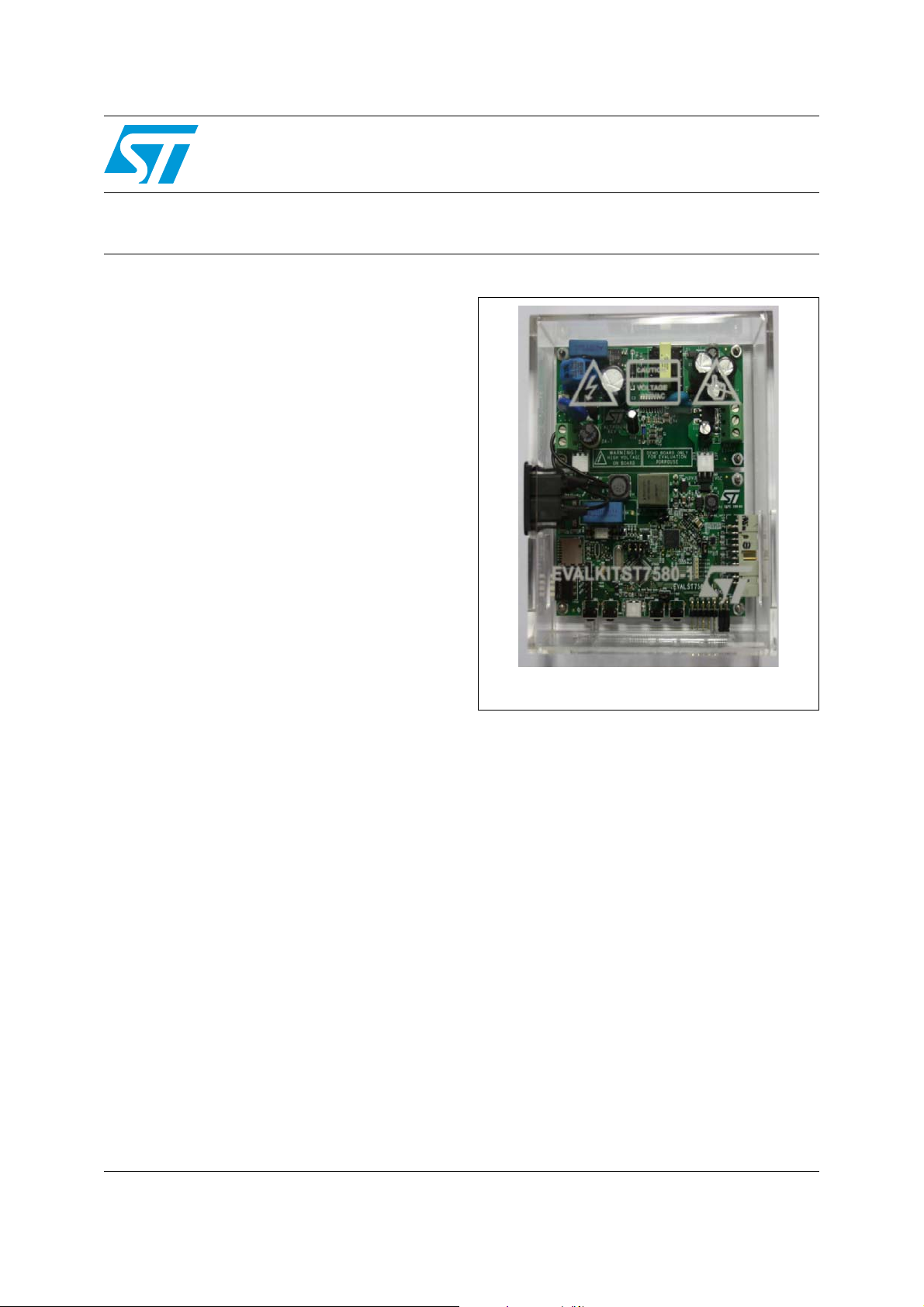
EVALKITST7580-1
Features
■ Suitable for point-to-multipoint 2-way power
line communication (PLC) over AC mains
■ Flexible 2-board architecture:
– EVALST7580-1, PLC board based on the
ST7580 narrow-band FSK/PSK power line
networking system-on-chip
– EVLALTAIR900-M1, wide-range input
voltage, 7.5 W power supply board based
on the ALTAIR04-900 quasi-resonant
current-mode SMPS controller
■ STM32 microcontroller hosted on the
EVALST7580-1 board to handle the ST7580
device and build a standalone power line node
■ External access through several interface
types: USB, SPI, I
■ Opportunity to save and load data to/from an
external µ-SD card
■ Intuitive graphical user interface (GUI) for the
Windows
®
environment with fully
programmable transceiver parameters
■ Suitable for CENELEC EN50065 and FCC part
15 compliant applications
2
C, USART, JTAG
EVALKITST7580-1
demonstration kit
Data brief
Description
Built around the ST7580 power line networking
system-on-chip, this demonstration kit embeds all
the functions required for a “turnkey” power line
communication network: the PLC node based on
the ST7580, the AC power supply (based on the
ALTAIR4-900 chip) and the STM32
microcontroller, to either control the system as a
standalone application or to connect the
EVALKITST7580-1 to an external host.
The typical application environment consists of
two or more EVALKITST7580-1s connected to the
same mains line, each being controlled by a PC
running the ST7580 GUI software.
February 2012 Doc ID 022818 Rev 1 1/4
For further information contact your local STMicroelectronics sales office.
www.st.com
4
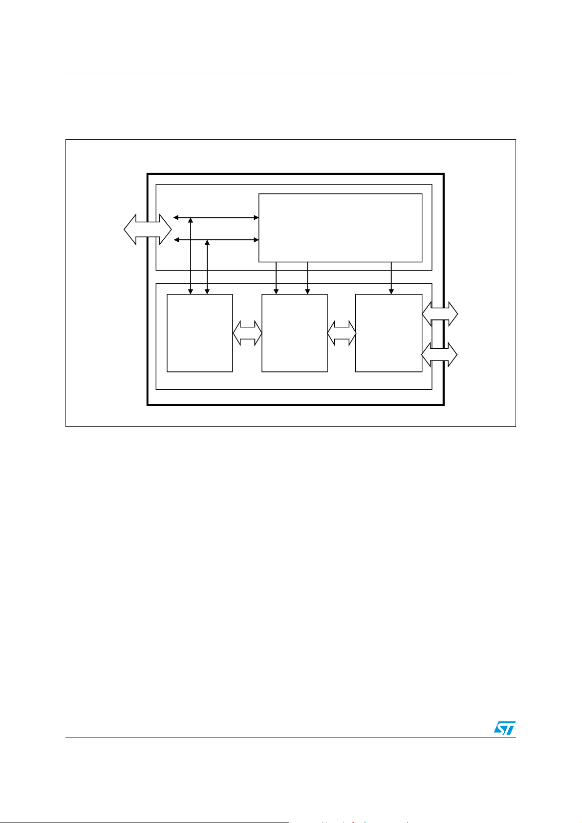
Block diagram EVALKITST7580-1
AC mains
connector
EVALKITST7580-1
LINE
NEUTRAL
Power Supply board
EVLALTAIR900-M1
Power Supply Unit
EVALST7580-1
Line coupling
ST7580
Modem
STM32
Microcontroller
13 V
3.3 V
USB. SPI,
I2C, JTAG
connectors
µ-SD card
3.3 V
AM10279V1
1 Block diagram
Figure 1. EVALKITST7580-1 functional block diagram
2/4 Doc ID 022818 Rev 1

EVALKITST7580-1 Revision history
2 Revision history
Table 1. Document revision history
Date Revision Changes
15-Feb-2012 1 Initial release.
Doc ID 022818 Rev 1 3/4

EVALKITST7580-1
Please Read Carefully:
Information in this document is provided solely in connection with ST products. STMicroelectronics NV and its subsidiaries (“ST”) reserve the
right to make changes, corrections, modifications or improvements, to this document, and the products and services described herein at any
time, without notice.
All ST products are sold pursuant to ST’s terms and conditions of sale.
Purchasers are solely responsible for the choice, selection and use of the ST products and services described herein, and ST assumes no
liability whatsoever relating to the choice, selection or use of the ST products and services described herein.
No license, express or implied, by estoppel or otherwise, to any intellectual property rights is granted under this document. If any part of this
document refers to any third party products or services it shall not be deemed a license grant by ST for the use of such third party products
or services, or any intellectual property contained therein or considered as a warranty covering the use in any manner whatsoever of such
third party products or services or any intellectual property contained therein.
UNLESS OTHERWISE SET FORTH IN ST’S TERMS AND CONDITIONS OF SALE ST DISCLAIMS ANY EXPRESS OR IMPLIED
WARRANTY WITH RESPECT TO THE USE AND/OR SALE OF ST PRODUCTS INCLUDING WITHOUT LIMITATION IMPLIED
WARRANTIES OF MERCHANTABILITY, FITNESS FOR A PARTICULAR PURPOSE (AND THEIR EQUIVALENTS UNDER THE LAWS
OF ANY JURISDICTION), OR INFRINGEMENT OF ANY PATENT, COPYRIGHT OR OTHER INTELLECTUAL PROPERTY RIGHT.
UNLESS EXPRESSLY APPROVED IN WRITING BY TWO AUTHORIZED ST REPRESENTATIVES, ST PRODUCTS ARE NOT
RECOMMENDED, AUTHORIZED OR WARRANTED FOR USE IN MILITARY, AIR CRAFT, SPACE, LIFE SAVING, OR LIFE SUSTAINING
APPLICATIONS, NOR IN PRODUCTS OR SYSTEMS WHERE FAILURE OR MALFUNCTION MAY RESULT IN PERSONAL INJURY,
DEATH, OR SEVERE PROPERTY OR ENVIRONMENTAL DAMAGE. ST PRODUCTS WHICH ARE NOT SPECIFIED AS "AUTOMOTIVE
GRADE" MAY ONLY BE USED IN AUTOMOTIVE APPLICATIONS AT USER’S OWN RISK.
Resale of ST products with provisions different from the statements and/or technical features set forth in this document shall immediately void
any warranty granted by ST for the ST product or service described herein and shall not create or extend in any manner whatsoever, any
liability of ST.
ST and the ST logo are trademarks or registered trademarks of ST in various countries.
Information in this document supersedes and replaces all information previously supplied.
The ST logo is a registered trademark of STMicroelectronics. All other names are the property of their respective owners.
© 2012 STMicroelectronics - All rights reserved
STMicroelectronics group of companies
Australia - Belgium - Brazil - Canada - China - Czech Republic - Finland - France - Germany - Hong Kong - India - Israel - Italy - Japan -
Malaysia - Malta - Morocco - Philippines - Singapore - Spain - Sweden - Switzerland - United Kingdom - United States of America
www.st.com
4/4 Doc ID 022818 Rev 1
 Loading...