How it Works
Log In / Sign Up
Buy Points
How it Works
FAQ
Contact Us
Questions and Suggestions
Users
ST
Loading...
E
EMIF06-10006C2
EMIF06-10006F2
EMIF06-1002F2
EMIF06-1005M12
EMIF06-1005N12
EMIF06-1502M12
EMIF06-AUD01F2
EMIF06-HMC01F2
EMIF06-mSD01F2
EMIF06-mSD02C3
EMIF06-MSD02N16
EMIF06-MSD03F3
EMIF06-MSD04F3
EMIF06-SD02F3
EMIF06-SD03F3
EMIF06-VID01C2
EMIF06-VID01F2
EMIF07-LCD02F3
EMIF07-LCD03F3
EMIF08-1005M16
EMIF08-1502M16
EMIF08-LCD04M16
EMIF08-VID01F2
EMIF09-SD01F3
EMIF10-1K010F2
EMIF10-COM01C2
EMIF10-COM01F2
EMIF10-LCD01C2
EMIF10-LCD02F3
eMotion
2
EN60555
ESDALC6V1-1BM2
ESDALC6V1P5
ESDALC6V1xxM6
ETC9310
ETC9311
ETC9410
ETC9411
EVAL5980
EVAL5981
EVAL5983
EVAL5985
EVAL5986
EVAL5986A
EVAL5987
EVAL5987A
EVAL6206Q
EVAL6208Q
EVAL6235PD
EVAL6235Q
EVAL6470H
EVAL6470PD
EVAL6472H
EVAL6474H
EVAL6520-1421
EVAL6902D
EVALHVLED805
EVALKITST7570-1
EVALKITST7580-1
EVALKITSTKNX
EVAL-L9001
EVAL-L9177A
EVAL-L9960
EVALPM8803-FLY
EVALPM8803-FWD
EVAL-RHRICL1AFV1
EVAL-RHRICL1ALV1
EVAL-RHRICL1ATV1
EVALSP1310CPU
EVALSP1340CPU
EVALSP320SCPU
2
EVALSP320SHMI
EVALSP320SPLC
2
EVALSP820-XS
EVALSPEAr300
2
EVALSPEAr310
EVALSPEAr320HMI
2
EVALSPEAr320PLC
EVALSPEAr600
EVALST7538DUAL
EVALSTPM32
EVALSTPM33
EVALSTPM34
EVALVIPER17L-7W
EVL150W-ADP-SR
EVL185W-LEDTV
EVL250W-ATX80PL
EVL6562A-TM-80W
EVL6566A-75WADP
EVL6566A-75WES4
EVL6566B-40WSTB
EVL6566B-65W-QR
EVLALTAIR05T-5W
EVLALTAIR900-M1
F
FC30
FL-101
FLC01-200B
FLC01-200B-TR
FLC01-200H
FLC10-200B
Loading...
Loading...
Nothing found
EVAL5987
User Manual
6 pgs
287.59 Kb
0
Table of contents
Loading...
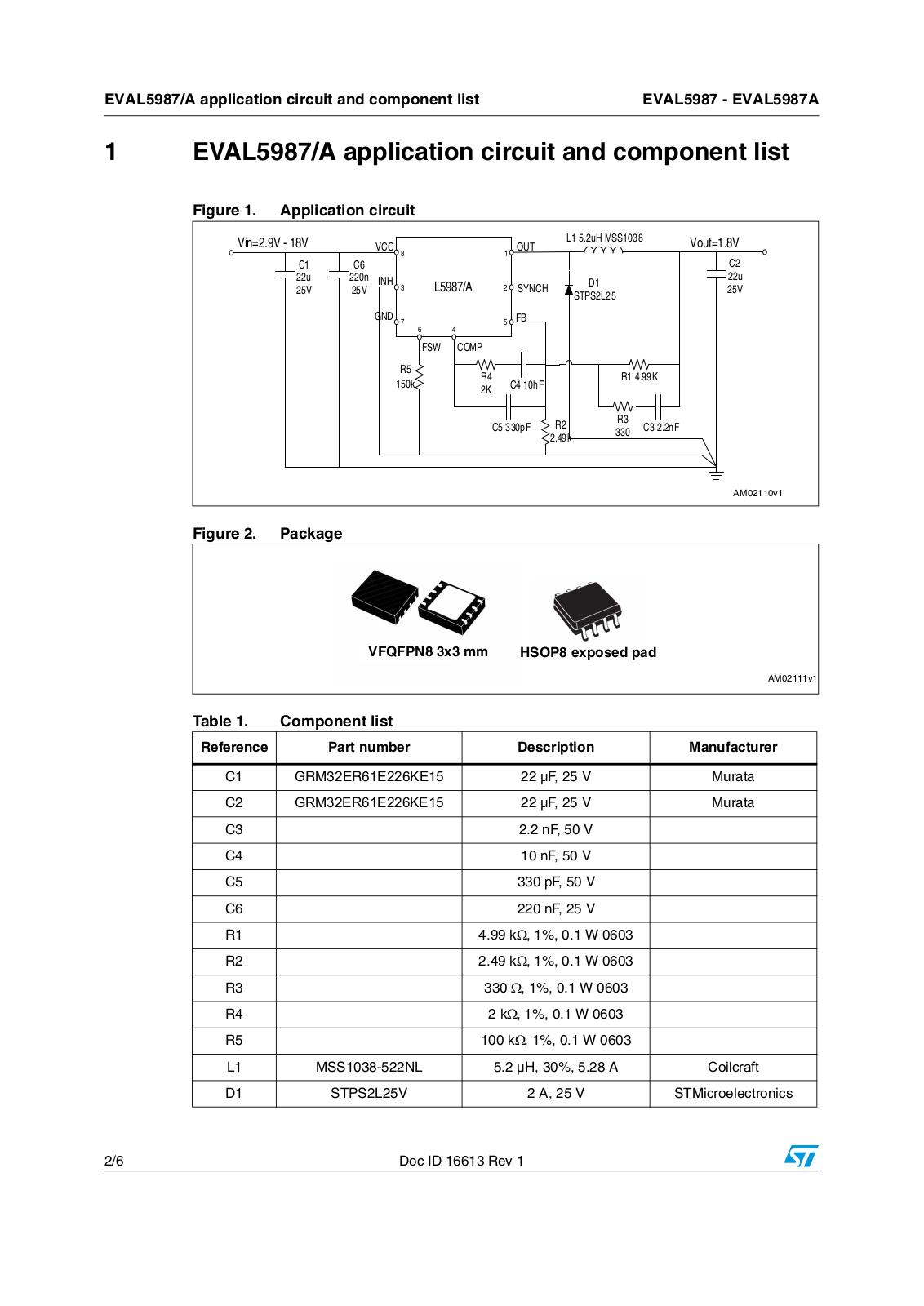
ST EVAL5987, EVAL5987A User Manual
...
ST User Manual
Download
Specifications and Main Features
Frequently Asked Questions
User Manual
Download
Loading...
+
hidden pages
Unhide
You need points to download manuals.
1 point = 1 manual.
You can buy points or you can get point for every manual you upload.
Buy points
Upload your manuals
 Loading...