

Page 1
1 A step-down switching regulator demonstration board
Features
■ 1 A DC output current
■ 2.9 V to 18 V input voltage
■ Output voltage adjustable from 0.6 V to 16 V
■ 250 kHz switching frequency, programmable
up to 1 MHz
■ Internal soft-start and inhibit
■ Low dropout operation: 100 % duty cycle
■ Zero-load current operation
■ Over-current and thermal protection
■ VFQFPN8 3 mm x 3 mm package
EVAL5981
based on the L5981
Data Brief
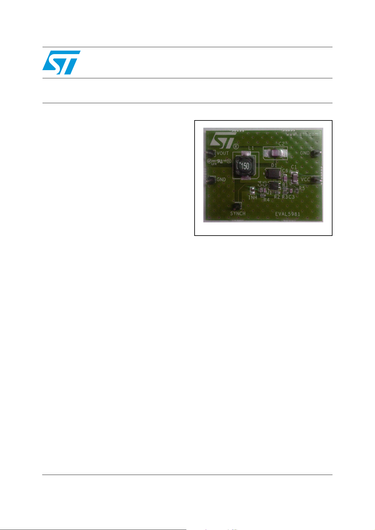
EVAL5981
Description
The EVAL5981 demonstration board provides the
design engineer with a fully functional step-down
switching regulator with an output current of up to
1 A. The L5981 integrates STMicroelectronics
step-down switching regulator, together with all
the external components required for a typical
application.
The rated voltage of the input capacitor and the
Schottky diode rectifier repetitive peak reverse
voltage are both 25 V, making the board capable
of covering the entire 2.9 V - 18 V input voltage
range of the L5981 device.
The board features an external resistor divider
(R1 and R2) designed for an output voltage
of 3.3 V.
The output voltage can be set to a level from 0.6 V
up to the rated voltage of the output capacitor
(16 V).
The compensation network on the demonstration
board allows the use of MLCC as output filter to
keep the loop stable. The inductor saturation
current and forward current of the Schottky diode
are within the current limit values.
The switching frequency on the demonstration
board is set to 500 kHz by means of the R5
resistor connected to pin Fsw.
March 2009 Rev 1 1/6
For further information contact your local STMicroelectronics sales office.
www.st.com
6
Page 2
EVAL5981 EVAL5981 application circuit and component list
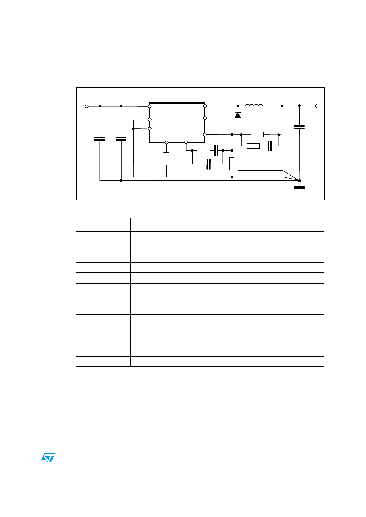
1 EVAL5981 application circuit and component list
Figure 1. Application circuit
L1 15uH
VCC
VCC
VCC
VIN=3.3V to 18V
VIN=3.3V to 18V
VIN=3.3V to 18V
VIN=3.3V to 18V
C1
C1
C1
C1
10uF
10uF
10uF
10uF
C6
C6
C6
C6
68nF
68nF
68nF
68nF
VCC
INH
INH
INH
INH
GND
GND
GND
GND
R5 100K
R5 100K
Table 1. Component list
OUT
OUT
OUT
OUT
1
1
1
1
1
1
1
4
4
4
4
1
2
2
2
2
5
5
5
5
R4 3.9K
R4 3.9K
C5 150pF
C5 150pF
SYNCH
SYNCH
SYNCH
SYNCH
FB
FB
FB
FB
C4 10nF
C4 10nF
C4 10nF
C4 10nF
8
8
8
8
3
3
3
3
L5985
L5981
L5985
FSW
FSW
FSW
FSW
6
6
6
6
L5981
COMP
COMP
COMP
COMP
COMP
COMP
COMP
COMP
7
7
7
7
L1 15uH
D1
D1
D1
D1
STPS2L25U
STPS2L25U
STPS2L25U
STPS2L25U
R1 4.99K
R1 4.99K
R1 4.99K
R1 4.99K
R2 1.1K
R2 1.1K
R2 1.1K
R2 1.1K
Vout=3.3V
Vout=3.3V
Vout=3.3V
Vout=3.3V
C2
C2
C2
C2
22uF
22uF
22uF
22uF
C3 3.3nFR3 180
C3 3.3nFR3 180
Reference Part number Description Manufacturer
C1 GRM31CR61E106KA12 10 μF, 25 V MURATA
C2 GRM32ER61E226KE15 22 μF, 25 V MURATA
C3 3.3 nF, 50 V
C4 10 nF, 50 V
C5 150 pF, 50 V
C6 68 nF, 25 V
R1 4.99 kΩ, 1 %, 0.1 W 0603
R2 1.1 kΩ, 1 %, 0.1 W 0603
R3 180 Ω, 1 %, 0.1 W 0603
R4 3.9 kΩ, 1 %, 0.1 W 0603
R5 100 kΩ, 1 %, 0.1 W 0603
D1 STPS2L25V 2 A, 25 V STMicroelectronics
L1 7447779115 15 μH, 20 %, 2.2 A Wurth elektronik
2/6
Page 3

EVAL5981 PCB layout
2 PCB layout
Figure 2. PCB layout (component side)
Figure 3. PCB layout (bottom side)
Figure 4. PCB layout (front side)
3/6
Page 4

EVAL5981 Package mechanical data
3 Package mechanical data
In order to meet environmental requirements, ST offers these devices in different grades of
ECOPACK
specifications, grade definitions and product status are available at: www.st.com.
ECOPACK
®
packages, depending on their level of environmental compliance. ECOPACK®
®
is an ST trademark.
4/6
Page 5

EVAL5981 Revision history
4 Revision history
Table 2. Document revision history
Date Revision Changes
02-Mar-2009 1 Initial release
5/6
Page 6

EVAL5981
Please Read Carefully:
Information in this document is provided solely in connection with ST products. STMicroelectronics NV and its subsidiaries (“ST”) reserve the
right to make changes, corrections, modifications or improvements, to this document, and the products and services described herein at any
time, without notice.
All ST products are sold pursuant to ST’s terms and conditions of sale.
Purchasers are solely responsible for the choice, selection and use of the ST products and services described herein, and ST assumes no
liability whatsoever relating to the choice, selection or use of the ST products and services described herein.
No license, express or implied, by estoppel or otherwise, to any intellectual property rights is granted under this document. If any part of this
document refers to any third party products or services it shall not be deemed a license grant by ST for the use of such third party products
or services, or any intellectual property contained therein or considered as a warranty covering the use in any manner whatsoever of such
third party products or services or any intellectual property contained therein.
UNLESS OTHERWISE SET FORTH IN ST’S TERMS AND CONDITIONS OF SALE ST DISCLAIMS ANY EXPRESS OR IMPLIED
WARRANTY WITH RESPECT TO THE USE AND/OR SALE OF ST PRODUCTS INCLUDING WITHOUT LIMITATION IMPLIED
WARRANTIES OF MERCHANTABILITY, FITNESS FOR A PARTICULAR PURPOSE (AND THEIR EQUIVALENTS UNDER THE LAWS
OF ANY JURISDICTION), OR INFRINGEMENT OF ANY PATENT, COPYRIGHT OR OTHER INTELLECTUAL PROPERTY RIGHT.
UNLESS EXPRESSLY APPROVED IN WRITING BY AN AUTHORIZED ST REPRESENTATIVE, ST PRODUCTS ARE NOT
RECOMMENDED, AUTHORIZED OR WARRANTED FOR USE IN MILITARY, AIR CRAFT, SPACE, LIFE SAVING, OR LIFE SUSTAINING
APPLICATIONS, NOR IN PRODUCTS OR SYSTEMS WHERE FAILURE OR MALFUNCTION MAY RESULT IN PERSONAL INJURY,
DEATH, OR SEVERE PROPERTY OR ENVIRONMENTAL DAMAGE. ST PRODUCTS WHICH ARE NOT SPECIFIED AS "AUTOMOTIVE
GRADE" MAY ONLY BE USED IN AUTOMOTIVE APPLICATIONS AT USER’S OWN RISK.
Resale of ST products with provisions different from the statements and/or technical features set forth in this document shall immediately void
any warranty granted by ST for the ST product or service described herein and shall not create or extend in any manner whatsoever, any
liability of ST.
ST and the ST logo are trademarks or registered trademarks of ST in various countries.
Information in this document supersedes and replaces all information previously supplied.
The ST logo is a registered trademark of STMicroelectronics. All other names are the property of their respective owners.
© 2009 STMicroelectronics - All rights reserved
STMicroelectronics group of companies
Australia - Belgium - Brazil - Canada - China - Czech Republic - Finland - France - Germany - Hong Kong - India - Israel - Italy - Japan -
Malaysia - Malta - Morocco - Singapore - Spain - Sweden - Switzerland - United Kingdom - United States of America
www.st.com
6/6
 Loading...