

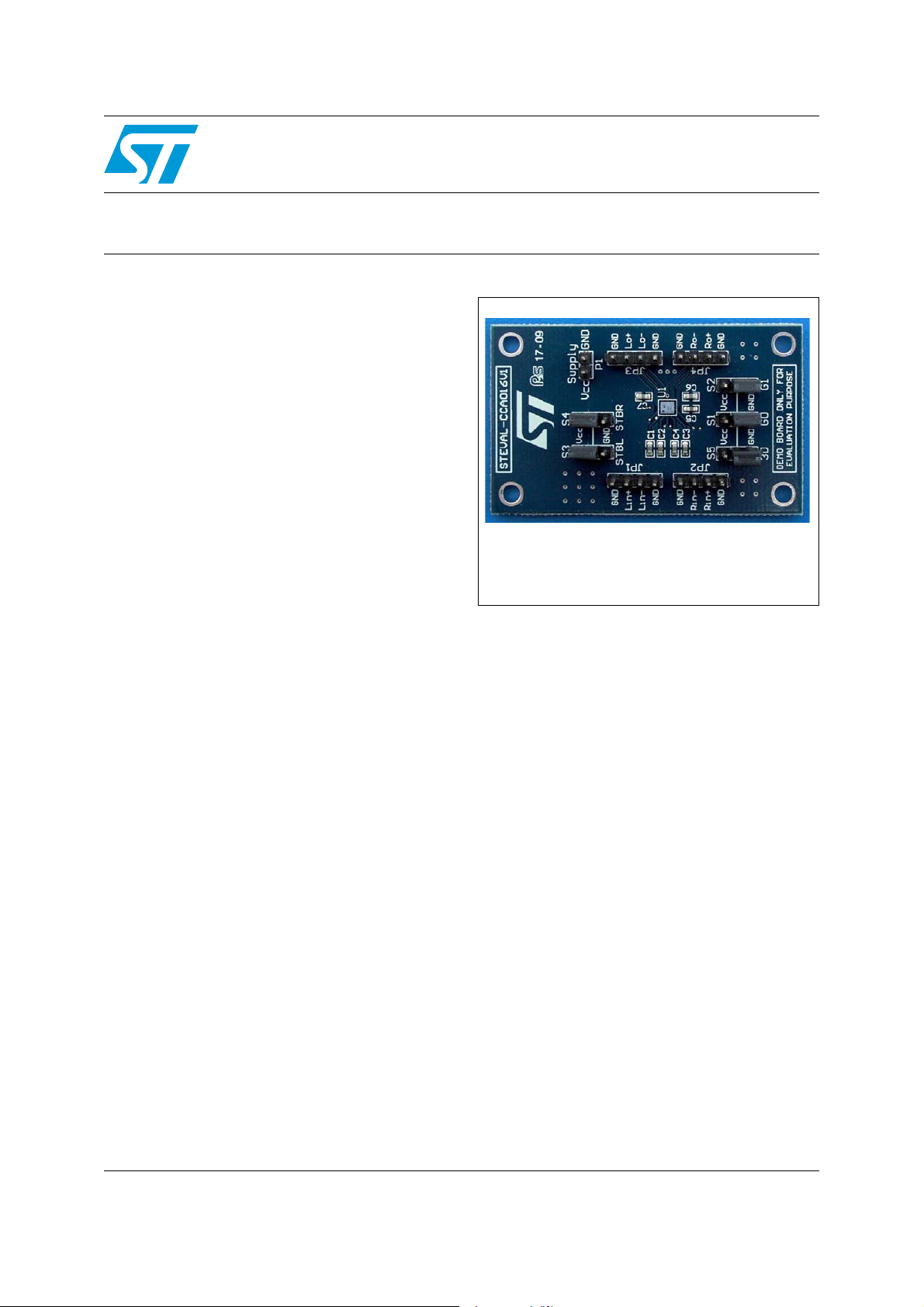
STEVAL-CCA016V1
Filter-free stereo 2.8 W Class-D audio power amplifier
demo board with selectable 3D sound effects based on the TS4999
Data brief
Features
■ Operating range from V
■ Dedicated standby mode active low for each
= 2.4 V to 5.5 V
CC
channel
■ Output power per channel: 2.8 W at 5 V into 4
Ω with 10% THD+N
■ Output power per channel: 0.7 W at 3.6 V into
8 Ω with 1% THD+N max.
■ Selectable 3D sound effect
■ Four gain setting steps: 3.5, 6, 9.5 and 12 dB.
■ Low current consumption
■ PSRR: 63 dB typ @ 217 Hz.
■ Fast start-up phase: 7.8 ms
■ Output short-circuit and thermal shutdown
protection
■ RoHS compliant
Description
This demonstration board is designed to evaluate
the performances of TS4999, that is a stereo fully
differential Class-D power amplifier.
STEVAL-CCA016V1
It can drive up to 1.35 W into a 8 Ω load at 5 V per
channel. The device has four different gain
settings utilizing two discrete pins, G0 and G1.
Pop and click reduction circuitry provides low
on/off switch noise while allowing the device to
start within 8 ms.
3D enhancement effects are selected through
one digital input pin that allows more amazing
stereo audio sound.
Two standby pins (active low) allow each channel
to be switched off separately.
The TS4999 is available in a 18 bumps Flip-Chip
package.
June 2009 Doc ID 15864 Rev 1 1/5
For further information contact your local STMicroelectronics sales office.
www.st.com
5
Circuit schematic and BOM list STEVAL-CCA016V1
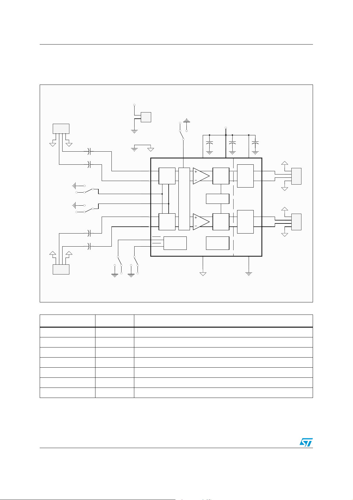
1 Circuit schematic and BOM list
Figure 1. Schematic diagram
Vcc
P1 Vcc
1
Lin+
Lin-
GND
GND
123
4
JP1
C1
220nF
C2
220nF
S1
3
2
1
VCC
G0
S2
3
2
1
VCC
G1
C3
220nF
C4
220nF
123
4
JP2
Rin+
Rin-
GND
GND
LinP
LinN
RinP
RinN
2
S3
STBL
1
3
VCC VCC
2
U1
Lin+
A1
Lin-
B2
G0
C3
G0
C5
G1
G1
E1
Rin+
D2
Rin-
A3
STBYL
STBL
E3
STBYR
STBR
2
TS4999 - FC18
S4
STBR
1
3
Gain
Select
Gain
Select
Standby
Control
VCC
C5
100nF
PWM
Vcc
D6
RPVCC
C6
1uF
LPVCC
H
Bridge
C7
1uF
B6
Lout+
Lout-
A5
A7
JP3
1
2
3
4
Header 4
1
3
S5
3D
2
C13D
D4
AVCC
Oscillator
3D EFFECT
PWM
H
Bridge
Rout+
Rout-
E5
E7
JP4
1
2
3
4
Header 4
Protection
Circuit
PGNDAGND
B4
C7
Table 1. Components list for the demonstration board
Designation Quantity Description
C1, C2, C3, C4 4 220 nF/16 V, SMD ceramic capacitor, 0603
C5 1 100 nF/16 V, SMD ceramic capacitor, 0603
C6, C7 1 1 µF/16 V, SMD ceramic capacitor, 0603
P1 1 2-pin header 2.54 mm pitch
S1, S2, S3, S4, S5 5 3-pin header 2.54 mm pitch
JP1, JP2, JP3, JP4 4 4-pin header 2.54 mm pitch
U1 1 TS4999 class-D audio amplifier
2/5 Doc ID 15864 Rev 1
 Loading...