

®
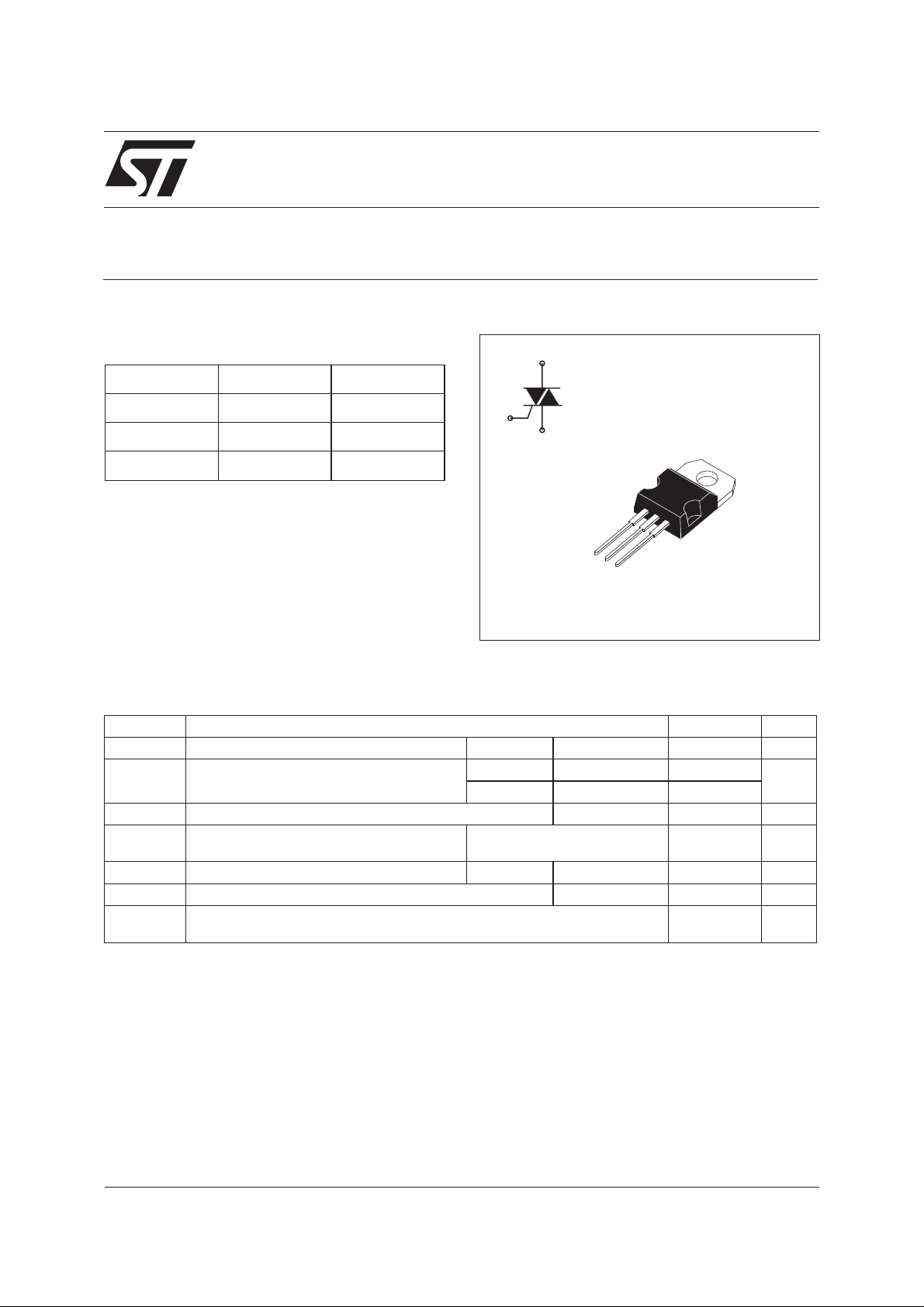
BTB04-600SL
STANDARD 4A TRIAC
MAIN FEATURES
A2
Symbol Value Unit
I
T(RMS)
V
DRM/VRRM
I
GT(Q1)
4A
600 V
10 mA
G
A1
A2
DESCRIPTION
The BTB04-600SL 4 quadrants TRIAC is intended
for general purpose applications where high surge
current capability is required, such as lighting,
A1
A2
G
corded power tools, industrial.
This TRIAC features a gate current capability
TO-220AB
sensitivity of 10mA.
ABSOLUTE MAXIMUM RATINGS
Symbol Parameter Value Unit
I
T(RMS)
I
TSM
2
I
dI/dt Criticalrateofriseofon-statecurrent
I
GM
P
G(AV)
Tstg
Tj
RMS on-state current (full sine wave) TO-220AB Tc = 105°C 4 A
Non repetitive surge peak on-state current
(full cycle, Tj initial = 25°C)
tI
2
t value for fusing tp = 10ms 6 A2s
F=50Hz t=20ms 35 A
F = 60 Hz t = 16.7 ms 38
Repetitive F = 100Hz 50 A/µs
I
=2xIGT,tr≤100 ns
G
Peak gate tp = 20µs Tj = 125°C 4 A
Average gate power dissipation Tj = 125°C 0.5 W
Storage junction temperature range
Operating junction temperature range
-40 to +150
-40 to +125
°C
March 2002 - Ed: 1A
1/5
BTB04-600SL
ELECTRICAL CHARACTERISTICS (Tj = 25°C, unless otherwise specified)
Symbol Test conditions Quadrant Value Unit
(1)
I
GT
VD= 12V RL=30Ω I - II - III MAX. 10 mA
IV MAX. 25
V
GT
V
GD
(2)
I
H
I
L
VD= 12V RL=30Ω ALL MAX. 1.3 V
VD=V
DRM
RL= 3.3kΩ Tj = 125°C ALL MIN. 0.2 V
IT= 100mA MAX. 15 mA
IG= 1.2I
GT
I - III - IV MAX. 15 mA
II 25
(2)
dV/dt
(dV/dt)c
VD= 67% V
(2)
(dI/dt)c = 1.8A/ms Tj = 125°C MIN. 10 V/µs
gate open Tj = 125°C MIN. 75 V/µs
DRM
STATIC CHARACTERISTICS
Symbol Test Conditions Value Unit
(2)
V
TM
V
TO
Rd
I
DRM
I
RRM
Note 1: minimumIGT is guaranted at 5% of IGT max.
Note 2: for both polarities of A2 referenced to A1.
ITM= 5A tp = 380µs Tj = 25°C MAX. 1.5 V
(2)
Threshold voltage Tj = 125°C MAX. 0.85 V
(2)
Dynamic resistance Tj = 125°C MAX. 100 mΩ
V
DRM=VRRM
Tj = 25°C
MAX. 5
Tj = 125°C
1
µA
mA
THERMAL RESISTANCE
Symbol Parameter Value Unit
Rth (j-c) Junction to case (AC) 3 °C/W
Rth (j-a) Junction to ambient 60 °C/W
2/5

BTB04-600SL
PRODUCT SELECTOR
Part Number Voltage Sensitivity Type Package
BTB04-600SL 600V 10 mA Standard TO-220AB
ORDERING INFORMATION
BT B 04 - 600 SL
S: SENSITIVITY = 10mA
TRIAC SERIES
L: LIGHTING APPLICATION
INSULATION
B: non insulated
CURRENT:4A
Fig. 1: Maximum power dissipation versus RMS
on-state current
P(W)
5
α=180°
4
3
2
180°
1
IT(RMS)(A)
0
0.0 0.5 1.0 1.5 2.0 2.5 3.0 3.5 4.0
α
α
Fig. 3: Relative variation of thermal impedance
versus pulse duration.
K = [Zth/Rth]
1.E+00
Zth(j-c)
1.E-01
Zth(j-a)
VOLTAGE: 600V
Fig. 2: RMS on-state current versus case
temperature.
IT(RMS)(A)
5.0
4.5
4.0
3.5
3.0
2.5
2.0
1.5
1.0
0.5
0.0
0 25 50 75 100 125
Tc(°C)
α=180°
Fig.4:On-state characteristics (maximumvalues)
ITM(A)
100
Tj=25°C
Tj=125°C
10
1.E-02
tp(s)
1.E-03
1.E-03 1.E-02 1.E-01 1.E+00 1.E+01 1.E+02 1.E+03
Tj max. :
Vto = 0.85V
VTM(V)
1
012345678910
Rd = 100 mW
3/5

BTB04-600SL
Fig.5:Surge peak on-statecurrentversus number
of cycles.
ITSM(A)
40
35
t=20ms
Repetitive
Tc=110°C
Non repetitive
Tj initial=25°C
Number of cycles
30
25
20
15
10
5
0
1 10 100 1000
Fig. 7: Relative variation of gate trigger current,
holding current and latching current versus junction temperature (typical values).
IGT,IH, IL[Tj] / IGT,IH, IL [Tj = 25°C]
3.0
2.5
2.0
1.5
1.0
0.5
0.0
-40 -30 -20 -10 0 10 20 30 40 50 60 70 80 90 100 110 120 130
IGT
IH & IL
Tj(°C)
Fig. 6: Non repetitive surge peak on-state current
for a sinusoidal pulse with width tp < 10ms, and
corresponding value of I
ITSM(A), I t (A s)
1000
100
10
1
0.01 0.10 1.00 10.00
22
dI/dt limitation:
50A/µs
2
t.
tp(ms)
Tj initial=25°C
ITSM
I²t
Fig.8:Relative variation ofcriticalrate of decrease
of main current versus reapplied dV/dt (typical values).
(dI/dt)c [(dV/dt)c] / Specified (dI/dt)c
2.0
1.8
1.6
1.4
1.2
1.0
0.8
0.6
0.4
0.2
0.0
0.1 1.0 10.0 100.0
dV/dt (V/µs)
Fig. 9: Relative variation of critical rate of decrease
of main current versus junction temperature.
(dI/dt)c [Tj] / (dI/dt)c [Tj = 125°C]
8
7
6
5
4
3
2
1
0
25 50 75 100 125
4/5
Tj(°C)
Fig. 10: Relative variation of static dV/dt immunity
versus junction temperature.
dV/dt [Tj] / dV/dt [Tj = 125°C]
8
7
6
5
4
3
2
1
0
25 50 75 100 125
Tj(°C)
VD=VR=400V

PACKAGE MECHANICAL DATA
TO-220AB (Plastic)
H2
Dia
L5
L6
L2
F2
F1
F
G1
G
L9
L4
BTB04-600SL
DIMENSIONS
REF.
A 4.40 4.60 0.173 0.181
A
C
C 1.23 1.32 0.048 0.051
D 2.40 2.72 0.094 0.107
E 0.49 0.70 0.019 0.027
L7
F 0.61 0.88 0.024 0.034
F1 1.14 1.70 0.044 0.066
F2 1.14 1.70 0.044 0.066
G 4.95 5.15 0.194 0.202
D
G1 2.40 2.70 0.094 0.106
H2 10 10.40 0.393 0.409
L2 16.4 typ. 0.645 typ.
M
E
L4 13 14 0.511 0.551
L5 2.65 2.95 0.104 0.116
L6 15.25 15.75 0.600 0.620
L7 6.20 6.60 0.244 0.259
L9 3.50 3.93 0.137 0.154
M 2.6 typ. 0.102 typ.
Diam. 3.75 3.85 0.147 0.151
Millimeters Inches
Min. Max. Min. Max.
OTHER INFORMATION
Ordering type Marking Package Weight Base qty Packing mode
BTB04-600SL BTB04-600SL TO-220AB 2.3g 50 Tube
Informationfurnished is believedto be accurateandreliable. However, STMicroelectronicsassumes no responsibilityforthe consequences of
useof such informationnor for anyinfringement of patentsor other rightsof third partieswhichmay result fromits use. Nolicense is grantedby
implication or otherwise under any patent or patent rights of STMicroelectronics. Specifications mentioned in this publication are subject to
change without notice. This publication supersedes and replaces all information previously supplied.
STMicroelectronics products are not authorized for use as critical components in life support devices or systems without express written approval of STMicroelectronics.
The ST logo is a registered trademark of STMicroelectronics
© 2002 STMicroelectronics - Printed in Italy - All rights reserved.
STMicroelectronics GROUP OF COMPANIES
Australia - Brazil - Canada - China - Finland - France - Germany
Hong Kong - India - Israel - Italy - Japan - Malaysia - Malta - Morocco - Singapore
Spain - Sweden - Switzerland - United Kingdom - United States.
http://www.st.com
5/5
 Loading...