

ST ANT2-M24LR16E User Manual
20 mm x 40 mm antenna reference board
-36
-,2%2
2&7)0"539
6##
2&7)0"539
3#,
3$!
6/54
!#
!#
'.$
6##
6/54
&ILTERING
CIRCUIT
)#BUS
KΩ
for the M24LR16E-R Dual Interface EEPROM
Features
■ Ready-to-use printed circuit board (PCB)
including
– 20 mm x 40mm 13.56 MHz inductive
antenna etched on the PCB
– M24LR16E-R Dual Interface EEPROM
2
–I
C connector
– Energy harvesting output (V
10 nF capacitance filtering circuit
– RF WIP/BUSY output with 20 kΩ
resistor, to indicate that an RF operation is
ongoing
Description
The ANT2-M24LR16E antenna reference board is
a ready-to-use PCB that features an M24LR16ER Dual Interface EEPROM IC connected to a
20 mm x 40 mm 13.56 MHz etched RF antenna
on one side, and to an I
The ANT2-M24LR16E antenna allows system
designers to evaluate the M24LR16E-R
2
C bus on the other side.
OUT
) with a
pull-up
ANT2-M24LR16E
Data brief
performance and capabilities, and to get started
with their design.
To demonstrate the energy harvesting function,
the ANT2-M24LR16E can be used in conjunction
with ST DEMO-CR95HF-A demonstration board.
The application can be powered directly from the
M24LR16E-R V
The ANT2-M24LR16E Gerber files can be
downloaded from http://www.st.com.
OUT
pin.
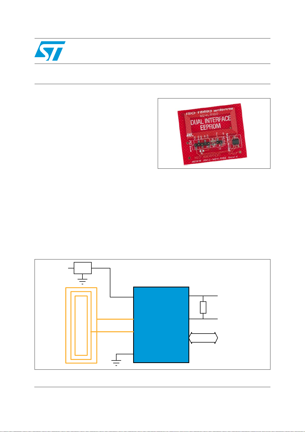
Figure 1. Block diagram
January 2012 Doc ID 022274 Rev 2 1/4
For further information contact your local STMicroelectronics sales office.
www.st.com
4

Associated firmware and PC software ANT2-M24LR16E
Associated firmware and PC software
The ANT2-M24LR16E board is supported by a PC software, the Dual Interface EEPROM
tool software, that allows to configure and control the energy harvesting. This software is
available from http://www.st.com.
Refer to application note AN3954 “Developing your own Visual Basic or C/C++ application
on a DEMO-CR95HF-A demonstration board”, for how to adapt the PC software for your
application.
2/4 Doc ID 022274 Rev 2
 Loading...