

Page 1

AN991
®
APPLICATION NOTE
L6569 - L6561 LIGHTING APPLICATION WITH PFC
by I. Dal Santo, U. Moriconi
DESCRIPTION
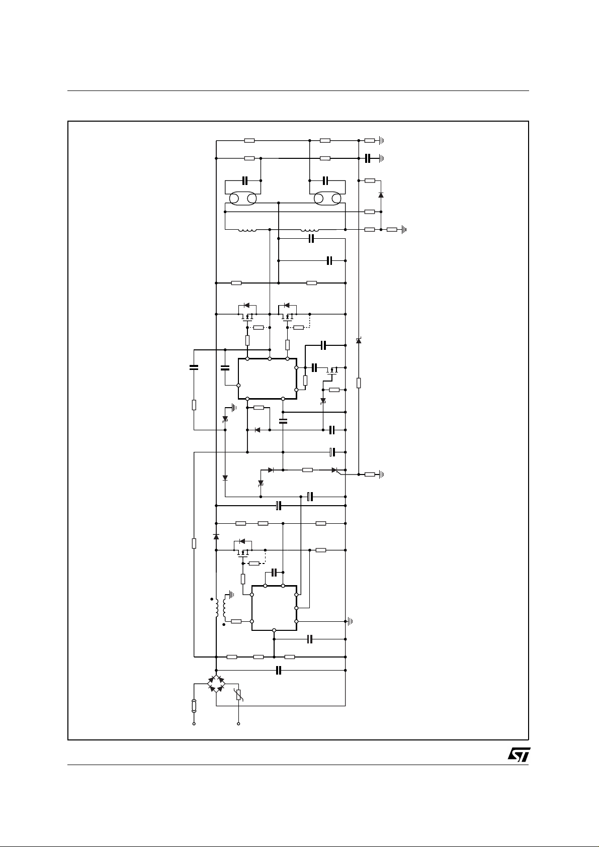
The application has been developed t o supply two 18W fluorescent lamps. It consists of two sections: a
Power Factor Corrected preregulator (PFC), using the L6561, and the lamp ballast stage with the L6569
(see fig.1).
The power factor corrector section is based on the L6561. This is an IC intended to control PFC preregulators by using the transition mode technique. It is especially dedicated for elect ronic lamp ballast applications (to better understand the L6561 characteristics refer to AN966).
Referring to the application circuit (see fig.1), the AC mains voltage is rectified by a diodes bridge and
delivered to the boost converter. The converter section boosts the rectif ied voltage to a DC controlled
value. The section consists of a boost inductor (T
an output capacitor (C5) and, obviously, a control circuitry.
Since the input is a time-variable supply voltag e (sine wave), to make the input cur rent shaped like the
line voltage, the converter has to produce a boost inductor average current like the rectified input voltage. To do so, the L6561 controls the system in transition mode. Transition mode approach consists of a
"zero current turn-on" system, switching at var iable frequency and duty cycle. The output voltage value
of the PFC, which can be adjusted by the pair of resistor R
The regulated voltage is delivered to the ballast section. The L6569 is a high voltage half-bridge driver
with a built-in oscillator, similar to a NE555 timer (to better under stand the L6569 in lighting applications
refer to AN880). T he load c onsists of a L-C series resonant cir cuit with the lamps connected across the
capacitors. This topology allows to operate in Zero Voltage Switching, t o reduce the tr ansistor switching
losses and the electromagnetic interference generated by the output wiring of the lamp.
The preheating of the lamp cathodes is achieved by a high switching frequency, about 80 kHz (R
), as current flows in the filaments, without lamp ignition. The preheating t ime is defined by the time
C
14
constant R
. After this time has elapsed, the switching frequency decreases moving towards the
12 C10
resonance one (L1/L2, C16/C17), thus increasing the voltage across the lamps and causing the ignition. In
steady state the frequency reaches 44 kHz (R
At start up, when the PFC is not running, the ballast controller (L6569) is powered by R
last section is running, the current pump (C12, R13, D3 and DZ2) allows to start up the power factor section and supply the overall circuit. This sequence prevents the ac tivation of the PFC over voltage protection. In fact if the PFC starts first, it is not loaded as long as the ballast is not operating.
The application is provided with a safety circuitry that, in case of open load or ignition failure, shuts down
the supply of the two controllers. This fault condition is latched by the SCR until the mains is removed
and the turn-on sequence is repeated.
), a controlled power switch (Q1), a boost diode (D1),
1
, is set at 400 Volt.
7-R8
, C13+C14).
14
. When the bal-
9
14
,
June 2002
1/3
Page 2
AN991 APPLICATION NOTE
Figure 1. Schematic circuit
C12
R13 47
820pF 600V
R23
820K
R21
820K
C16
630V
6.8nF
LP1
L1
2.3mH
R19
330K
Q2
STP6NB50Q3STP6NB50
10K
R17
R15 10
7
C11 100nF
8
1
R12
2.2M
18V
D4
6
L6569
1N4148
L2
10K
R18
R16 10
5
23
4
C9
100nF
R11
2.3mH
C15A
R20
C13
R14
DZ3
22
250V
100nF
180K
470pF
16K
5.6V
R24
R22
C17
C14
1.5M
1.5M
6.8nF
LP2
C15
560pF
Q4
R31
C10
C8
630V
250V
100nF
BS170
1.5M
470nF
10µF
82K
R25
1µF
C18
220
R27
R30
2.2M
R26
2.2M
DZ4 20V
R10 56K
D5
1N4148
56K
R28
D98IN822A
2/3
D1 BYT11600
R9 220K 1W
T1
Bridge
FUSE
Vac
176 to 265
D3 1N4148 DZ2
R7
Q1
STP5NK50Z
R4 10
R3
R1
750K
68K
750K
NTC
DZ1 4.7V
R7A
R29
5.6K
7
5
R1A
100
750K
2
750K
D2
1N4148
C3
L6561
3
C1
C5
680nF
1
220nF
22µF
450V
48
6
R2
8.2K
400V
SCR
C6
10µF
P0102AA
R8
9.53K
1
R6
C2
10nF
R32
Page 3

AN991 APPLICATION NOTE
Information furnished is bel ieved to be accurate and reliable. Howev er, STM icroele ctronics ass umes no respons ibilit y for the consequence s
of use of such i nformation nor for any i nfringement of patents or ot her rights of third parties which may result from its use. No l icense is
granted by impli cation or otherwis e under any patent or patent righ ts of STMicroelectro nics. Specification mentioned i n this publication are
subject to change withou t notice. This publica tion supersed es and replac es all informat ion previousl y supplied. STMic roelectro nics products
are not authorized for use as critical components in life support devices or systems without express written approval of STMicroelectronics.
The ST logo is a registered trademark of STMicroelectronics
© 2002 STMicroelectronics – Printed in Italy – All Rights Reserved
STMicroelectronics GROUP OF COMPANIES
Australia - Brazil - Canada - China - Finland - France - Germany - Hong Kong - India - Israel - Italy - Japan - Malaysia - Malta - Morocco -
Singapore - Spain - Sweden - Switzerland - United Kingdom - United States.
http://www.st.com
3/3
 Loading...