

Page 1

AN980
APPLICATION NOTE
ST7 KEYPAD DECODING TECHNIQUES,
IMPLEMENTING WAKE-UP ON KEYSTROKE
by 8-Bit Micro Application Laboratory
INTRODUCTION
The goal of this application note is to present an example of the use of the HALT mode.
In this application, the MCU (here a ST72F264) is waked up by an external interrupt caused by
someone pressed a key on the 4x4 matrixed keypad.
AN980/0802 1/8
1
Page 2
ST7 KEYPAD DECODING TECHNIQUES, IM PLEMENTING WAKE-UP ON KEYSTROKE
1 ST7 / KEYBOARD INTERFACE
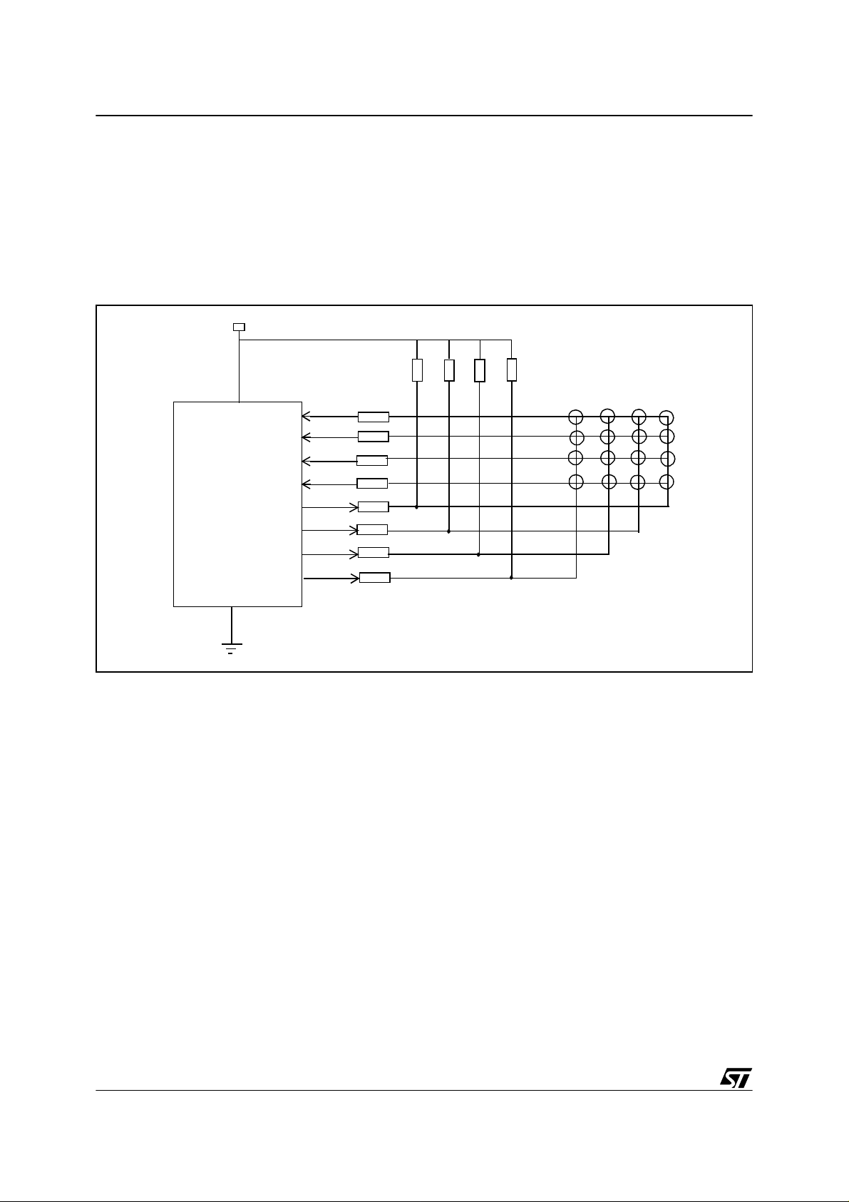
Rows are connected to inputs with p u ll-up and interrupts (Por t C). Columns are connected to
Port A configured as output. The result of the interrupt (the value of the pr essed key) is sent on
LEDS (Port B) and stored into the X register. In our configuration, we have to add 4 pul l-up r esistors on Port A (from PA0 to PA3) to be able to appl y a high level on the corresponding pads.
Figure 1. ST7 / keypad interface set-up
4x100k
8x560
V
DD
PC0
PC1
PC2
PC3
ST7
PA0
GND
PA1
PA2
PA3
2/8
2
Page 3

ST7 KEYPAD DECODING TECHNIQUES, IMPLEMENTING WAKE-UP ON KEYSTROKE
2 ST72F264 CONFIGURATION
The application has been validated with a ST72F264. Its configuration i s described in this part.
Refer to your datasheet for more details.
2.1 I/O CONTROL
Rows are connected to pins configured as inputs (Port C as input with pull up and interrupts).
Columns are connected to pins configured as outputs (Port A).
External interrupts are caused by a low level applied to a pin of Port C (caused by a key
pressed), they wake up the MCU which was in HALT mode.
Port B is configured as outputs to send the value of the pressed key on LEDS.
Please, refer to the Data Book to configure pins properly.
2.2 MISCELLANEOUS REGISTER
Bits 7 and 6 have to be set to configure events correctly: the external interrupt (EI1) has here
to be caused by a falling edge only.
Please, refer to the datasheet for more details.
2.3 HALT MODE
The HALT instruction places the ST72F264 in its lowest power consumption mode. The core
and all peripherals are frozen. In this mode, the internal oscillator is turned off, causing all internal processing to be halted. The data remain unchanged. During the HALT mode, external
interrupts are still enabled. The MCU stays in this state until an external interrupt or a reset occurs. Then the internal oscillator is restarted and the core waits for 4096 CPU clock cycles
(512 µs for a f
= 8MHz) before running the extern al interrup t subroutine . Then the MCU
CPU
comes back to the main program (in our application to the HALT state).
Please, refer to the datasheet for more details.
3/8
Page 4

ST7 KEYPAD DECODING TECHNIQUES, IM PLEMENTING WAKE-UP ON KEYSTROKE
3 EXTERNAL INTER RU PTS
The MCU is in HALT mode. When a key is pressed, a low level is applied to the pin corresponding to the row the key belongs (pins configured as inputs with pull -up). It’s a fal ling edge
applied to a pin of Port C which creates an external interrupt (EI1) and wakes up the MCU. The
MCU executes then the external interrupt subroutine (decoding the press ed key) and c omes
back to its previous state (HALT state in the main program).
4 KEYPAD
The keypad used is a 4x4 matrixed keypad. Rows are connected to pins configured as inputs
with pull-up. So the initial st ate of these pi ns are a high level (1). When a key is pressed, a l ow
level is applied to the corresponding pin. For this reason, the keypad is coded as follows:
Table 1. Key values
KEY
row
value
1 0x0E 0x0E 7 0x0B 0x0E
2 0x0E 0x0D 8 0x0B 0x0D
3 0x0E 0x0B 9 0x0B 0x0B
F 0x0E 0x07 D 0x0B 0x07
4 0x0D 0x0E A 0x07 0x0E
5 0x0D 0x0D 0 0x07 0x0D
6 0x0D 0x0B B 0x07 0x0B
E 0x0D 0x07 C 0x07 0x07
123F
456
7
column
value
8
9
KEY
E
D
PC0
PC1
PC2
row
value
column
value
4/8
A
PA0
0
PA1
B
PA2
C
PA3
PC3
Page 5

ST7 KEYPAD DECODING TECHNIQUES, IMPLEMENTING WAKE-UP ON KEYSTROKE
You have to press the chosen key at least 0.5 to 1 second depending on which key you
choose (table read from keypad_top to keypad). The faster the key is read into the table, the
faster it will be decoded and the faster the result will be sent on LEDS.
The keypad code is in the file constant.asm as follows:
.keypad DC.B $0E,$0E,$1 ;PC0 PA0
DC.B $0E,$0D,$2 ;PC0 PA1
DC.B $0E,$0B,$3 ;PC0 PA2
DC.B $0E,$07,$F ;PC0 PA3
DC.B $0D,$0E,$4 ;PC1 PA0
DC.B $0D,$0D,$5 ;PC1 PA1
DC.B $0D,$0B,$6 ;PC1 PA2
DC.B $0D,$07,$E ;PC1 PA3
DC.B $0B,$0E,$7 ;PC2 PA0
DC.B $0B,$0D,$8 ;PC2 PA1
DC.B $0B,$0B,$9 ;PC2 PA2
DC.B $0B,$07,$D ;PC2 PA3
DC.B $07,$0E,$A ;PC3 PA0
DC.B $07,$0D,$0 ;PC3 PA1
DC.B $07,$0B,$B ;PC3 PA2
keypad_top DC.B $07,$07,$C ;PC 3 PA3
5/8
Page 6

ST7 KEYPAD DECODING TECHNIQUES, IM PLEMENTING WAKE-UP ON KEYSTROKE
5 FLOWCHARTS
Figure 2. Flowchart: Main program
Initializations
infinite
loop
Figure 3. Flowchart: external interrupt (EI1)
X = 48 (3x16 coded values)
one column activated
(PA0...PA3)
Is there a low level on the
intersection of the stored
row and column?
yes
HALT
no
store into X
next column
value
6/8
corresponding value of the pressed key
stored into A, X and sent on LEDS
EXIT
Page 7

ST7 KEYPAD DECODING TECHNIQUES, IMPLEMENTING WAKE-UP ON KEYSTROKE
6 SOFTWARE
All the source files in assembly code are given in the zip file with this application note.
The source files are for guidance only. STMicroelectronics shall not be held liable for any di-
rect, indirect or consequential damages with respect to any claims arising from use of this s oftware.
7/8
Page 8

ST7 KEYPAD DECODING TECHNIQUES, IM PLEMENTING WAKE-UP ON KEYSTROKE
“THE PRESENT NOTE WHICH IS FOR GUIDANCE ONLY AIMS AT PROVIDING CUSTOMERS WITH INFORMATION
REGARDING THE IR PRO DUCT S IN OR DER FO R THEM TO SAV E TIME . AS A RES ULT, STMIC ROEL ECTR ONI CS
SHALL NOT BE HELD LIABLE FOR ANY DIRECT, INDIRECT OR CONSEQUENTIAL DAMAGES WITH RESPECT TO
ANY CL AIM S AR IS IN G FR OM T HE CO N TENT OF S UC H A NO TE A ND /O R T HE U SE M AD E BY C US TO ME RS O F
THE INFORMATION CONTAINED HEREIN IN CONNECTION WITH THEIR PRODUCTS.”
Information furnished is believed to be accurate and reliable. However, STMicroelectronics assumes no responsibility for the consequences
of use of such information nor for any infringement of patents or other rights of third parties which may result from its use. No license is granted
by implic ation or otherwise under any patent or patent ri ghts of STM i croelectr oni cs. Spec i fications mentioned i n this publication are subje ct
to change without notice. This publication supersedes and replaces all information previously supplied. STMicroelectronics products are not
authorized for use as cri tical comp onents in life support dev i ces or systems wi thout the express written approv al of STMicroel ectronics.
The ST logo is a registered trademark of STMicroelectronics
2002 STMicroelectronics - All Rights Reserved.
STMicroelectronics Group of Compan i es
http://www.s t. com
Purchase of I
2
C Components by STMicroelectronics conveys a license under the Philips I2C Patent. Rights to use the se components in an
2
I
C system i s granted pro vi ded that the sy stem conforms to the I2C Standard Specification as defined by Philips.
Australi a - B razil - Canada - China - Finl and - France - Germany - Hong Kong - Ind ia - Israel - Italy - Japan
Malaysi a - M al ta - Morocco - Singapore - Spain - Sw eden - Switz erland - United Kingdom - U.S.A.
8/8
 Loading...