

Page 1

AN974
APPLICATION NOTE
Real time clock with ST7 Timer Output Compare
By MCD Application Team
1 INTRODUCTION
The purpose of this note is to present how to use the ST7 Timer output compare function. As
an applica tion exam ple, this do cumen t present s how to g enerate a re al time clo ck with
counters for seconds, minutes and hours, based on a fixed basic time base.
2 GENERATING A TIME BASE WITH ST7 TIMER
The ST7 timer output compare function can be used to generate the fixed time base.
2.1 TIMER CONFIGURATION AND INITIALIZATION
The application example is managed using the output compare interrupts. The ST7 timer has
two output compare func tions whos e interrupts ar e both enabled by the O CIE bi t in the CR 1
register. In this case, the Output Compare 1 (OC1) is used for time base generation while the
second one (OC2) is ignored when it generates an interrupt each time the free running counter
value matches the value in the OC2 register.
To minimize the CPU load, we need to c hoose the ma ximum tim e b ase value tha t has to be
multiplied to obtain one sec. For this reason the maximum timer clock divider ratio (1/8) is selected by the CC1 and CC0 bits in the CR2 register.
2.2 OUTPUT COMPARE UPDATE
To maintai n a fi xed ela psed tim e b etwee n e ach O utp ut Compa re 1 interrupt ge nerati on, th e
Output compare registers (OC1HR, OC1LR) have to be updated with a fixed offset time base
at each interrupt.
(OCxHR, OCxLR ) = (OCxHR, OCxLR) + (OCxHR OCxLR )
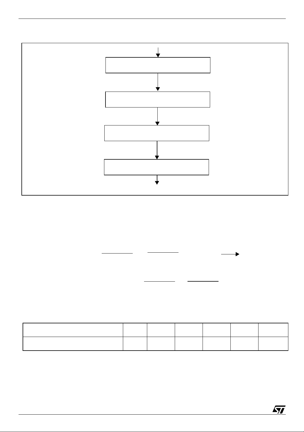
Caution: As the ST7 can only handles 8-bit data and as the output compare function is inhibited between the wri te in the high (OCxHR) and the low (OCx LR) output co mpare register s,
special care has to be taken when the updating of the 16-bit compare register. A typical algorithm flowchart is shown in Figure 1.
offset
AN974/0303 1/6
1
Page 2
Real time clock with ST7 Timer Output Comp are
Figure 1. Output Compare Register Updat e Flowch art
STORE OCxHR AND OCxLR REGISTER
VALUES IN TEMPORARY REGISTERS
UPDATE OCxHR AND OCxLR VALUES
THROUGH TEMPORARY REGISTERS
STORE NEW OCxHR REGISTER VALUE
STORE NEW OCxLR REGISTER VALUE
Based on the assumption that f
is 4-MHz, Table 1 gives some basic possible time bases
CPU
with the Output compare register offset value (OCxH R, OCxLR).
f
f
timercnt
=
CPU
(cc1,cc0)
(OCxHR OCxLR )
offset
4 MHz
=
8
TimeBase
=
T
timerc n t
=
500 KHz
TimeBase
=
2 us
Table 1. Output Compare Register and Timebase Values with f
Time Base [ms]
OCxHR OCxLR offset [hex]
2 10 20 50 100 131.07
03E8 1388 2710 61A8 C350 FFFF
3 REAL TIME CLOCK APPLICATION
timercnt
T
timercnt
at 500KHz
= 2 us
The real time clock application is based on four software counters (100ms, seconds, minutes
and hours) updated by a 100ms ST7 timer output compare 1 interrupt.
2/6
2
Page 3

Real time clock with ST7 Tim e r Ou tput Compare
These four counters are coded on one byte each and are updated by the Output Compare 1
interrupt routine as shown in Figure 2.
Figure 2. Software Count e r Update Flowchart
OC1 INTERRUPT
UPDATE
OCxHR AND OCxLR
REGISTER
INCREMENT 100ms COUNTER
no
100ms CNT
yes
RESET 100ms COUNTER
= 10 ?
INCREMENT SECOND
no
SECOND CNT
yes
= 60 ?
INCREMENT MINUTE
no
MINUTE CNT
yes RESET MINUTE
= 60 ?
INCREMENT HOUR
COUNTER
RESET SECOND
COUNTER
COUNTER
COUNTER
COUNTER
no
HOUR CNT
= 24 ?
yes
RESET HOUR
COUNTER
3/6
Page 4

Real time clock with ST7 Timer Output Comp are
3.1 HARDWARE CONFIGURATION
The real t ime clock ap plicat ion hardwa re i s m ade of a ST 723 24 microcon tr oller t im er wh ich
generates a 100m s ti me ba se t hroug h t he Tim er B O utput Co mpar e 1 fu nc tion . T wo o f the
software coun ters (sec onds a nd minu tes) are o utput by th e m icrocon toller t hrough I/O p orts
(PC, PF and PD) and displayed on LEDs as shown in Figure 3. The Seconds counter is shown
with a red LED and the Minutes counter is shown with a pink LED.
The selected crystal for this example has 8 MHz frequency which gives f
=4 MHz because
CPU
the PLL is disabled and slow mode is not selected.
Figure 3. Real Time Clock Applicatio n
LED
LED
LED
TIMER
OC registers
I/O
PORTS
PC
PF
2-7
0,1,4,6,7
PD0
SOFTWARE
RAM
ST72324
sw counter
The RTC accuracy depends on the clock sourc e (e.g. Resonato r Oscillator) a ccuracy. Care
should be taken especially for time critical applications.
4/6
Page 5

Real time clock with ST7 Tim e r Ou tput Compare
4 SOFTWARE
All the source files in assembly code as well as in C code are given in the zip file with this application note. The C code uses the software library (ST7 software library version 1.1).
The source files are for guidance only. STMicroelectronics shall not be held liable for any direct, indirect or consequential damages with respect to any claims arising from use of this s oftware.
5/6
Page 6

Real time clock with ST7 Timer Output Comp are
THE PRESENT NOTE WHICH IS FOR GUIDANCE ONLY AIMS AT PROVIDING CUSTOMERS WITH INFORMATION
REGARDING THE IR PRO DUCT S IN OR DER FO R THEM TO SAV E TIME . AS A RES ULT, STMIC ROEL ECTR ONI CS
SHALL NOT BE HELD LIABLE FOR ANY DIRECT, INDIRECT OR CONSEQUENTIAL DAMAGES WITH RESPECT TO
ANY CLAIMS ARISING FROM THE CONTENT OF SUCH A NOTE AND/OR THE USE MADE BY CUSTOMERS OF
THE INFORMATION CONTAINED HEREIN IN CONNECTION WITH THEIR PRODUCTS.”
Information furnished is believed to be accurate and reliable. However, STMicroelectronics assumes no responsibility for the consequences
of use of such information nor for any infringement of patents or other rights of third parties which may result from its use. No license is granted
by implic ation or otherwise under any patent or patent ri ghts of STM i croelectr oni cs. Specifications mentioned in thi s publicati on are subject
to change without notice. This publication supersedes and replaces all information previously supplied. STMicroelectronics products are not
authorized for use as cri tical comp onents in life support dev i ces or systems wi thout the express written approv al of STMicroel e ctronics.
The ST logo is a registered trademark of STMicroelectronics
2003 STMicroelectronics - All Rights Reserved.
STMicroelectronics Group of Compan i es
http://www.s t. com
Purchase of I
2
C Components by STMicroelectronics conveys a license under the Philips I2C Patent. Rights to use the se components in an
2
I
C system i s granted pro vid ed that the sy stem conforms to the I2C Standard Specification as defined by Philips.
Australi a - Brazil - Canada - China - Fi nl and - France - Germany - Hong Kong - India - Israel - I taly - Japan
Malaysi a - M al ta - Morocco - Singapore - Spain - Sw eden - Switz erland - United Kingdom - U.S.A.
6/6
 Loading...