

Page 1

AN969
APPLICATION NOTE
SCI COMMUNICATION BETWEEN ST7 AND PC
by Microcontroller Division Applications
INTRODUCTION
This document presents a standard communications interface between a ST7 microcontroller
and a PC. This communication is done through the ST7 SCI peripheral and a serial port of the
PC using the RS232 protocol.
AN969/0102 1/10
1
Page 2
SCI COMMUNICATION BETWEEN ST7 AND PC
1 SCI COMM UNICATION
The main features of the SCI communication peripheral are summarized below. Refer to your
ST7 datasheet for more details.
1.1 MAIN FEATURES
The Serial Communication Interface (SCI) offers a flex ible means of full-dupl ex data exchange
with external equipment requiring an industry standard NRZ asynchronous serial data format.
The SCI allows a very wide range of baud rates with different baud rates for transmission and
reception.
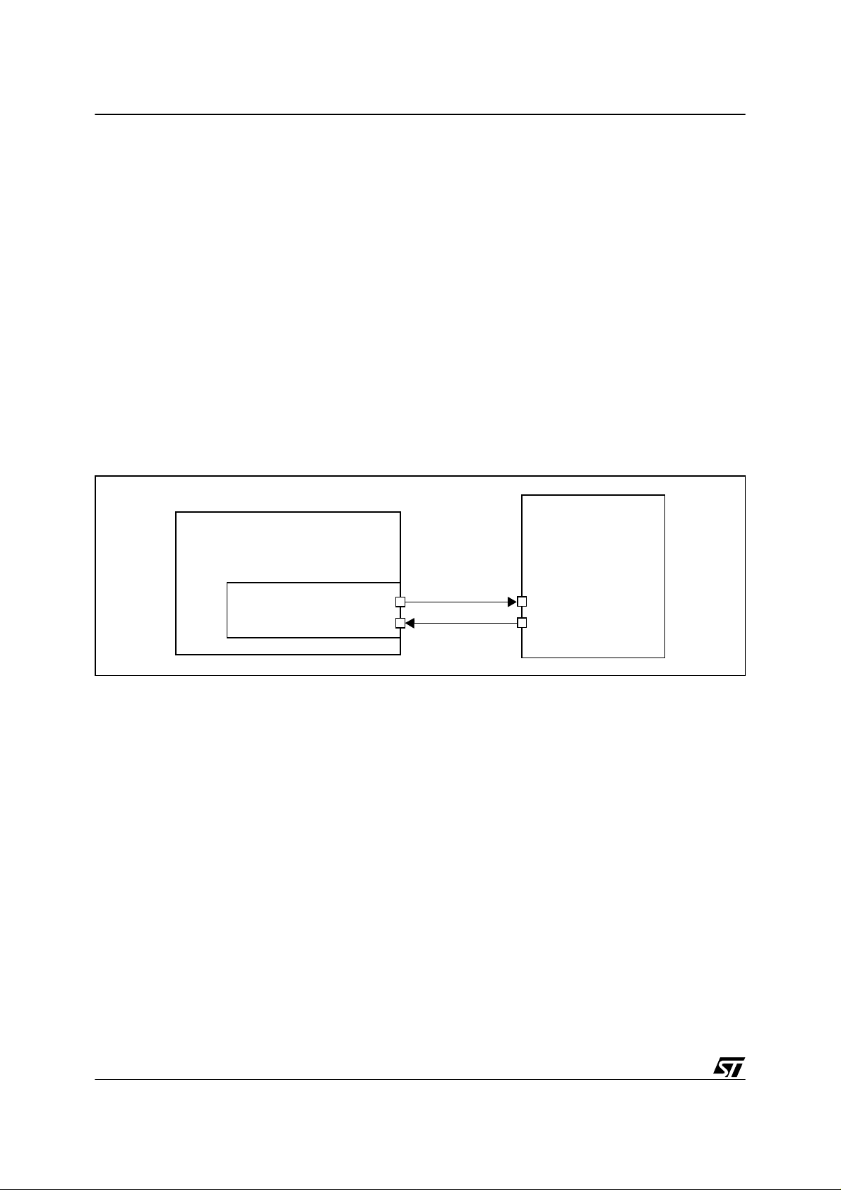
For SCI communication, only two signals are needed, one for transmission and the other for
reception. No cloc k signal is needed as it works in async hronous mode. Each dev ice has a
Transmit Data Output pin (TDO pin) and a Receive Data Input pin (RDI pin). See Figure 1.
Figure 1. ST7 and SCI interface set-up
DEVICE
ST7
SCI Interface
The user must be very careful in identifying the use of each pin. This can easily be done
putting the device in tr ansmission and checki ng with an osci lloscope if a transmission frame is
present or not.
1.2 BAUD RATES
Transmission and r eception can be driven by their own baud rate generator. However be
aware that to communicate correctly, the receiver must have a reception baud rate strictly
equal to the transmission baud rate of the transmitter. If not, the communication will be cor-
rupted. A s long as this condition is met, a wide range of baud rates is possible.
TDO
RDI
RDI
TDO
2/10
2
Page 3
SCI COMMUNICATION BETWEEN ST7 AND PC
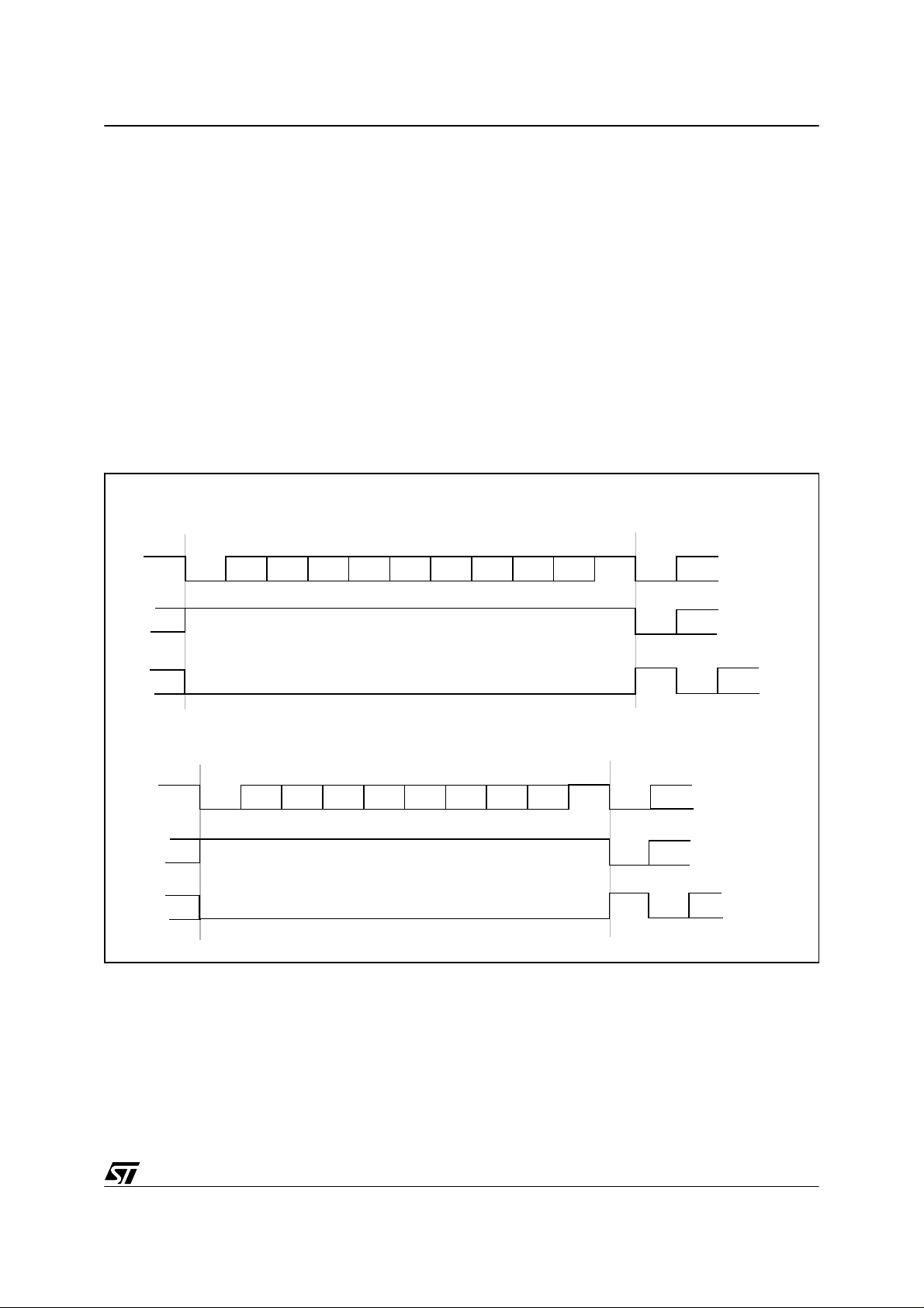
1.3 FRAMES
Any transmission is Least Significant Bit first. A data word can be 8 or 9 bits long. A data frame
begins with a «star t bit», which i s a ’0’ bit and ends wit h a «stop bit», wh ich is a ’1’ bit. See
Figure 2.
Two special frames are also managed :
An Idle character is interpreted as an entire frame of ’1’ bits followed by the start bit of the next
frame which contains data.
A Break character is detected when receiving ’0’ bits for some multiple of the frame period. At
the end of the last break, the transmitter inserts an extra ’1’ bit to acknowledge the next start
bit.
Figure 2. Frames and word length
9-bit Word length (M bit of SCICR1 is set)
Next Data Frame
Start
Bit
Bit0
Data Frame
Bit2
Bit1
Bit3
Bit4
Bit5 Bit6
Bit7
Bit8
Stop
Bit
Next
Start
Bit
Idle Frame
Break Fr ame
8-bit Word length (M bit of SCICR1 is reset)
Data Frame
Start
Bit
Bit0 Bit1
Bit2
Bit3 Bit4
Bit5 Bit6
Idle Frame
Break Frame
Bit7
Stop
Bit
Start
Bit
Start
Extra
’1’
Bit
Next Data Frame
Next
Start
Bit
Start
Bit
Start
Extra
Bit
’1’
3/10
Page 4

SCI COMMUNICATION BETWEEN ST7 AND PC
2 RS232 COMMUNICATION WITH A PC
2.1 MAIN FEATURES
The electrical and proto col c harac teristics o f R S232 are d iffe rent f rom th ose of the ST 7 SCI
peripheral. In RS232 communication, high level is typically +7V and low level is typica lly -7V,
while the SCI peripheral works with TTL levels (0, +5V).
Furthermore, the polarities are different. A ’1’ bit coming from the SCI corresponds to a ’0’ bit
in RS232, and a ’0’ bit to a ’1’ bit. It is true for all bits including t he start and stop bit.
So it is necessary to implement a conversion between the PC and the SCI peripheral. In this
application a MAX232 is used for this purpose.
2.2 PC CONFIGURATION
The PC will be use d as a terminal . The d escriptio n below r efers to th e Wi ndows 98 e nviron ment. This terminal application is called hyperterminal.
Under Windows, open the «hyperterminal» application. To configure it, go to the communication parameters menu. The options of this window must be the same as the ones defined with
your ST7.
After selecting the right serial communication port, select the same baud rate as the one configured in the micro. As the PC accepts only one baud rate, transmission and reception baud
rates will have the same value. Data word length will be 8 bits, but you can choose to use 1 or
2 stop bits. «F low c ontrol » can be either X on/X off or non e (the ST 72F2 64.ht file is also pro vided in the corresponding zip file).
The PC is then correctly configured.
4/10
Page 5

SCI COMMUNICATION BETWEEN ST7 AND PC
3 ST72F264 CONFIGURATION
This application was implemented with a ST72F264. This microcontroller uses a 16 MHz external clock (quartz). A desc ription of the baud rate selec tion is given later in this application
note.
3.1 GENERAL INITIALIZ ATION
The ST72F264 internal clock (f
) works at 16MHz/2 = 8MHz.
CPU
Two pins of the ST7 are used :
- the TDO pin (Transmit Data Output, alternate function of PA7).
- the RDI pin (Receive Data Input, alternate function of PA5).
The PA7, PA 5 pins mu st be in itializ ed as floati ng i npu ts (p lea se r efer to t he dat asheet ), t he
value of the Port A Data Register does not matter.
3.2 SCI CONFIGURATION
The peripher al is confi gu red u sing the 2 SC I C on trol R eg isters ( SCI CR1, SCIC R2 ), a nd the
Baud Rat e Reg ister ( BRR ) or th e 2 exte nde d baud rate r egis ters of the S T72F 264 (E TPR ,
ERPR).
As in this application a polling strategy is used, SCI interruptions are disabled (TIE, TCIE, RIE,
ILIE bits of SCICR2 register are reset).
3.2.1 Resetting control registers
First, the reset status is forced to the control registers and pending interrupts are cleared.
3.2.2 Baud rates selection
Then the baud rates must be selected. We should always have the same baud rates in the PC
and in the SCI.
In this application, the Extended Transmit Prescaler division Register (ETPR) and the Extended Rec eive Pr escaler di vision R egister (ERPR) ar e not use d and so ar e in rese t state.
Therefore the baud rates are calculated as follows:
TX = f
/(16*PR*TR) RX = f
CPU
/(16*PR*RR)
CPU
where PR = 1, 3, 4 or 13 (SCP0 and SCP1 bits in the BRR register), TR = 1, 2, 4, 8, 16, 32, 64
or 128 (SCT0, SCT1 and SCT2 bits of the BBR register) and RR = 1, 2, 4, 8, 16, 32, 64 or 128
(SCR0, SCR1 and SCR2 bits of the BR R register).
For example, in our application, if we want 9600 as baud rate, we have to choose PR = 13 and
TR = RR = 4.
5/10
Page 6

SCI COMMUNICATION BETWEEN ST7 AND PC
Note: ET PR and ER PR can be used to finetune the baud rate. W hen ETPR and ERPR con-
tain any value other than 0, the BRR register is disabled and the baud rates are given by the
formula:
TX = f
/(16*EPTR*PR*TR) RX = f
CPU
/(16*ERPR*PR*RR)
CPU
where EPTR and ERPR = 1 to 255.
3.2.3 Word length
The word length is selected by the M bit in the SCICR1 register.
70
R8 T8 SCID M WAKE PCE PS PIE
In the application, data length is always 8 bits, but the user can force a second stop bit. This
th
is done using a 9-bit word lengt h and settin g the 9
bit (T8 bit of SCICR1) . When rece iving
data, R8 bit will always be set (reception of 2 stop bits).
Special bits (PCE,PS,PIE) are also available to use the SCI with parity (not used in this appli-
cation). Refer to the datasheet for more information.
3.2.4 Selecting reception and transmission modes
The selection is made using the SCICR2 register.
70
TIE TCIE RIE ILIE TE RE RWU SBK
Transmission is enabled or disabled depending on the value of the TE bit of SCICR2 (TE = 1,
transmission enabled). When disabled, the TDO pin is free for general purpose I/O.
Reception is enabled or disabled depending on the value of the RE bit of SCICR2 (RE = 1, reception enabled). When disabled, the RDI pin is is free for general purpose I/O.
When reception is disabled, no data must be sent to the ST7. If data are to be received at this
time, the RE bit must be set. Otherwise a wrong byte might be detected when going back into
reception mode.
6/10
Page 7

SCI COMMUNICATION BETWEEN ST7 AND PC
4 SCI COMMUNICATION BETWEEN ST7 AND PC VIA RS232
The software for this application is the SCI driver. The complete software can be found in the
the ST internet webs ite. It is o f course only an exam ple. It is u p to the us er to adapt it to his
specific application.
4.1 GENERAL DE SCRIPTION
In this application, a ST72F264 is connected to a PC. The communication is performed using
the «hyperterminal» application of Windows 98.
Characters are sent by the PC in ASCII code to the ST7. Every 4 characters received by the
ST7 are sent back to the PC and can be read on its screen.
The software is a polling SCI communication between an ST72F264 and a PC via RS232. The
communication works at 9600bps and has 1 stop bit.
The first part of the program performs the initialization of the ST72F264, core and SCI peripheral.
Then it enters transmission mode, sends the content of a 4-byte buffer to the PC. The initialized value of the buffer is «test» in ASCII code. When the 4 characters are sent, transmission
mode is ended and the SCI peripheral enters reception mode.
In reception m ode, the software w aits for the user to sen d 4 ASCII ch aracter s from th e PC.
Each character is put in the buffer until the fourth is received. Then reception mode is ended,
and goes back to transmission mode which will send the new contents of the buffer and so on.
As the ST7 sends the same characters as received, it is very easy to check if the communication is correct. Note that this program does not manage communication errors.
4.2 HARDWARE
The ST7 SCI peripheral cannot be directly connected to a PC, as it uses the RS232 protocol.
The conversion betw een SCI and RS2 32 can be done us ing a MAX232. An ov erview sche matic is presented below (Figure 3.).
7/10
Page 8

SCI COMMUNICATION BETWEEN ST7 AND PC
Figure 3. Overview Schematic
TERMINAL
PC
seri al port
GROU ND
GND
GND
TD
RD TDO
OUTIN
OUT
MAX232
IN
ST72F264
GND
RDI
Be sure that the th ree main de vices ( PC, ST7, MA X232 ) have the sam e elec trical refe rence
(GND).
The Receive Data pin (RD) of the serial port of the PC must correspond to the TDO pin of the
ST7, and the Transmit Data pin (TD) to the RDI pin.
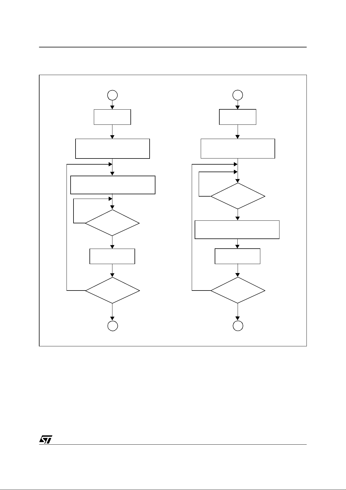
4.3 FLOWCHARTS
The flowcharts of the application are presented below (Figure 4., Figure 5.).
Figure 4. Initialization
start
ST72311 initialization
default value of buffer
SCI peripheral
initialization
A
8/10
Page 9
SCI COMMUNICATION BETWEEN ST7 AND PC
Figure 5. Transmission mode, R eception mode
A
Nb = 4
set SCI peripheral
in transmission mode
send the byte from
address (Nb-1) of buffer
no
byte sent ?
yes
Nb = Nb - 1
B
Nb = 4
set SCI peripheral
in reception mode
no
buffer at address (Nb-1)
new byte
received ?
yes
put new byte into
Nb = Nb - 1
no
Nb = 0 ?
yes
B
4.4 SOFTWARE
All the source files in assembly code are given in the zip file with application note.
The source files are for guidance only. STMicroelectronics shall not be held liable for any di-
rect, indirect or consequential damages with respect to any claims arising from use of this s oftware.
no
Nb = 0 ?
yes
A
9/10
Page 10

SCI COMMUNICATION BETWEEN ST7 AND PC
“THE PRESENT NOTE WHICH IS FOR GUIDANCE ONLY AIMS AT PROVIDING CUSTOMERS WITH INFORMATION
REGARDING THE IR PRO DUCT S IN OR DER FO R THEM TO SAV E TIME . AS A RES ULT, STMIC ROEL ECTR ONI CS
SHALL NOT BE HELD LIABLE FOR ANY DIRECT, INDIRECT OR CONSEQUENTIAL DAMAGES WITH RESPECT TO
ANY CL AIM S AR IS IN G FR OM T HE CO N TENT OF S UC H A NO TE A ND /O R T HE U SE M AD E BY C US TO ME RS O F
THE INFORMATION CONTAINED HEREIN IN CONNEXION WITH THEIR PRODUCTS.”
Information furnished is believed to be accurate and reliable. However, STMicroelectronics assumes no responsibility for the consequences
of use of such information nor for any infringement of patents or other rights of third parties which may result from its use. No license is granted
by implic ation or otherwise under any patent or patent ri ghts of STM i croelectr oni cs. Spec i fications mentioned i n this publication are subje ct
to change without notice. This publication supersedes and replaces all information previously supplied. STMicroelectronics products are not
authorized for use as cri tical comp onents in life support dev i ces or systems wi thout the express written approv al of STMicroel ectronics.
The ST logo is a registered trademark of STMicroelectronics
2002 STMicroelectronics - All Rights Reserved.
STMicroelectronics Group of Compan i es
http://www.s t. com
Purchase of I
2
C Components by STMicroelectronics conveys a license under the Philips I2C Patent. Rights to use the se components in an
2
I
C system i s granted pro vi ded that the sy stem conforms to the I2C Standard Specification as defined by Philips.
Australi a - B razil - Canada - China - Finl and - France - Germany - Hong Kong - Ind ia - Israel - Italy - Japan
Malaysi a - M al ta - Morocco - Singapore - Spain - Sw eden - Switz erland - United Kingdom - U.S.A.
10/10
 Loading...