

Introduction
AN925
Application note
Time update in ST’s TIMEKEEPER® devices
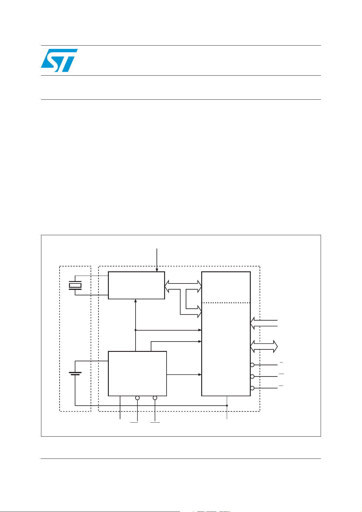
Figure 1 shows how the non-volatile, static memory array and the quartz-controlled clock
oscillator, of TIMEKEEPER
®
devices from STMicroelectronics, are interconnected through
the clock registers. The clock registers are mapped into the memory array (please see the
data sheet for the precise mapping) as 8 or 16 BYTEWIDE BIPORT memory cells. The time
data in these memory cells are updated from the clock side (the system side) and are made
available to the user side within the user’s finest time resolution.
However, the user’s finest time resolution is one second, so this leaves plenty of scope for
variability (of the order of several milliseconds) between one update and the next. Since this
variability might be noticeable to some applications (for example, those that poll the time
registers regularly, or those that use an alarm function that is triggered once per second),
this document sets out to explain the nature of the variability, to make it more predictable to
the applications designer.
Figure 1. Internal architecture of an ST TIMEKEEPER
INTEGRATED BATTERY
CRYSTAL AND
SNAPHAT
OSCILLATOR AND
CLOCK CHAIN
32,768 Hz
CRYSTAL
WDI
®
device
TIMEKEEPER
8, 16 x 8
REGISTERS
A0-AX
DQ0-DQ7
E
W
G
AI02482
LITHIUM
CELL
VOLTAGE SENSE
AND
SWITCHING
CIRCUITRY
V
CC
IRQ/FT RST
POWER
BATTERY LOW
V
PFD
SRAM ARRAY
V
SS
July 2012 Doc ID 5228 Rev 2 1/5
www.st.com
AN925
A 1 Hz clock signal, from the clock chain, is used to update the seconds register. Each rising
edge of the 1 Hz clock signal increments the system side of the seconds register. Having
updated the seconds register, a ripple carry to other registers might be initiated (for
example, incrementing the minutes register from 00 to 01, after the seconds register has
been incremented from 59 to 00). The longest possible ripple carry extends through all
seven registers: seconds, minutes, hours, day of the week, date of the month, month of the
year and year.
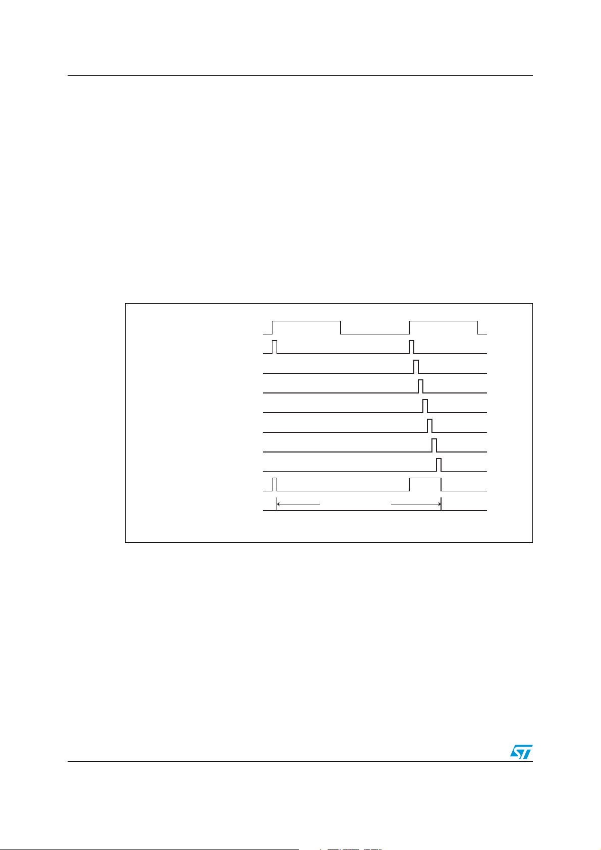
Figure 2 shows two consecutive updates of the seconds register. The first update only
updates the seconds register; the second update, though, ripples through all seven clock
registers. When the system-side time registers have finished being updated, they are copied
across to the user-side, thereby making the updated time available to the user. Thus, the
spacing between successive System-to-User-Update-Pulse is one second plus a delta
delay that can vary from 0.5 ms to 3.5 ms (1x0.5 ms to 7x0.5 ms). The older M48T58
(revision B), M48T59 (revision B), and M48T559 are examples of TIMEKEEPER
®
devices
that operate in this way.
Figure 2. Time update waveform diagram (variable delay)
1 Hz clock frequency
Seconds register update
Minutes register update
Hours register update
Day of week register update
Date register update
Month register update
Year register update
Reference update pulse
System to user update pulse
1 second + 3.5ms
00:00:00 79/1/195:95:32 69/13/21
AI02483
2/5 Doc ID 5228 Rev 2

AN925
An alternative approach, shown in Figure 3, is adopted by the newer M48T02, M48T12,
M48T08/Y, M48T18, M48T58/Y (revision C), M48T35/Y, M48T35AV, M48T37Y/V and
M48T201Y/V devices. The spacing between successive System-to-User-Update-Pulse is
always one second. Each pulse is delayed by the same delta time, of 3.5 ms, regardless of
the number of registers that need incrementing within that period.
Figure 3. Time update waveform diagram (fixed delay)
1 Hz clock frequency
Seconds register update
Minutes register update
Hours register update
Day of week register update
Date register update
Month register update
Year register update
Reference update pulse
System to user update pulse
= 1 second
(These examples are each shown with the calibration set to zero.)
00:00:00 79/1/195:95:32 69/13/21
AI02484
Doc ID 5228 Rev 2 3/5

Revision history AN925
Revision history
Table 1. Document revision history
Date Revision Changes
Dec-1998 1 Initial release.
17-Jul-2012 2 Textual updates concerning available TIMEKEEPER
®
devices.
4/5 Doc ID 5228 Rev 2

AN925
Please Read Carefully:
Information in this document is provided solely in connection with ST products. STMicroelectronics NV and its subsidiaries (“ST”) reserve the
right to make changes, corrections, modifications or improvements, to this document, and the products and services described herein at any
time, without notice.
All ST products are sold pursuant to ST’s terms and conditions of sale.
Purchasers are solely responsible for the choice, selection and use of the ST products and services described herein, and ST assumes no
liability whatsoever relating to the choice, selection or use of the ST products and services described herein.
No license, express or implied, by estoppel or otherwise, to any intellectual property rights is granted under this document. If any part of this
document refers to any third party products or services it shall not be deemed a license grant by ST for the use of such third party products
or services, or any intellectual property contained therein or considered as a warranty covering the use in any manner whatsoever of such
third party products or services or any intellectual property contained therein.
UNLESS OTHERWISE SET FORTH IN ST’S TERMS AND CONDITIONS OF SALE ST DISCLAIMS ANY EXPRESS OR IMPLIED
WARRANTY WITH RESPECT TO THE USE AND/OR SALE OF ST PRODUCTS INCLUDING WITHOUT LIMITATION IMPLIED
WARRANTIES OF MERCHANTABILITY, FITNESS FOR A PARTICULAR PURPOSE (AND THEIR EQUIVALENTS UNDER THE LAWS
OF ANY JURISDICTION), OR INFRINGEMENT OF ANY PATENT, COPYRIGHT OR OTHER INTELLECTUAL PROPERTY RIGHT.
UNLESS EXPRESSLY APPROVED IN WRITING BY TWO AUTHORIZED ST REPRESENTATIVES, ST PRODUCTS ARE NOT
RECOMMENDED, AUTHORIZED OR WARRANTED FOR USE IN MILITARY, AIR CRAFT, SPACE, LIFE SAVING, OR LIFE SUSTAINING
APPLICATIONS, NOR IN PRODUCTS OR SYSTEMS WHERE FAILURE OR MALFUNCTION MAY RESULT IN PERSONAL INJURY,
DEATH, OR SEVERE PROPERTY OR ENVIRONMENTAL DAMAGE. ST PRODUCTS WHICH ARE NOT SPECIFIED AS "AUTOMOTIVE
GRADE" MAY ONLY BE USED IN AUTOMOTIVE APPLICATIONS AT USER’S OWN RISK.
Resale of ST products with provisions different from the statements and/or technical features set forth in this document shall immediately void
any warranty granted by ST for the ST product or service described herein and shall not create or extend in any manner whatsoever, any
liability of ST.
ST and the ST logo are trademarks or registered trademarks of ST in various countries.
Information in this document supersedes and replaces all information previously supplied.
The ST logo is a registered trademark of STMicroelectronics. All other names are the property of their respective owners.
© 2012 STMicroelectronics - All rights reserved
STMicroelectronics group of companies
Australia - Belgium - Brazil - Canada - China - Czech Republic - Finland - France - Germany - Hong Kong - India - Israel - Italy - Japan -
Malaysia - Malta - Morocco - Philippines - Singapore - Spain - Sweden - Switzerland - United Kingdom - United States of America
www.st.com
Doc ID 5228 Rev 2 5/5
 Loading...