

Page 1

AN901
APPLICATION NOTE
EMC GUIDELINES FOR
MICROCONTROLLER-BASED APPLICATIONS
by Microcontroller Division Applications
INTRODUCTION
Electromagnetic compatibility (EMC) must be taken into account at the very beginning of a
project as the cost of correcting an EMC problem encountered at the start of production can be
far greater that the cost of a detailed EMC study during the development phase of an application.
The use of microco ntroller- based syste ms is increasin gly wide -spread, especia lly in s uch
areas as consumer, industrial and automotive applications, where the drive for cost reduction
is the common trend. This emphasis on cost reduction and the increasing complexity of such
systems requires the manufacturers of semiconductor componen ts to develop highly integrated, single chip, high operating frequency microcontrollers using the highest density technology possible. Unfo rtunatel y, for semico nductor struc tures, the highe r the density and the
faster the operation, intrinsically the higher the level of electrical noise generated, and the increased sensitivity to spikes induced from external noise. Therefore, the PCB layout, the soft-
ware and the system must now apply EMC “hardening” techniques in their design.
This note a ims to provi de gu ideline s for d esign ers of m icroco ntro ller-b ased applic ations so
that the optimum level of EMC performances can be achieved.
For general information about EMC performances, please refer to application note AN898.
AN901/1100 1/14
1
Page 2
EMC GUIDELINES FOR MICROCONTROLLER-BASED APPLICATIONS
1 DEFINITION OF TERMS
Electromagnetic compatibility (EMC) is the capacity of a piece of equipment to work properly
in its normal environment, and not create electrical di sturbances that would interfere w ith other
equipment.
Electromagnetic susceptibility (EMS) is the level of resistance to electrical disturbances such
as electromagnetic fields and conducted electrical noise.
Electromagnetic interference (EMI) is the level of conducted/radiated electrical noise created
by the equipment.
There exists several standards addressing EMS or EMI issues, and for every type of application area. These standards apply to finished equipment. Up to now, there is no official
standard applicable to sub-systems or electronic components. Nevertheless, EMC tests must
be performed on the sub-systems in order to evaluate and optimize applications for EMC performances.
1.1 EMC STANDARDS
Table 1. Electromagnetic Emissions
STANDARD
EN50081-1 Generic emissions standards - Residential
EN50081-2 Generic emissions standards - Industrial
EN55011 CISPR 11 For industrial, scientific and medical equipment
EN55013 CISPR 13 For broadcast receivers
EN 55014 CISPR 14 For household appliances/tools
EN 55022 CISPR 22 For data processing equipment
INTERNATIONAL STANDARD
SAE 1752/3 American Measurements Procedure for suscept ibility
EQUIVALENT
DESCRIPTION
Table 2. Electromagnetic Susceptibility
STANDARD
EN50082-1 Generic immunity standards - Residential
EN50082-2 Generic immunity standards - Industrial
EN50140
EN50141
EN50142
EN????
(TBD)
INTERNATIONAL STANDARD
IEC 1000-4-3
(old nb: IEC 801-3)
IEC 1000-4-6
(old nb: IEC 801-6)
IEC 1000-4-5
(old nb: IEC 801-5)
IEC 1000-4-4
(old nb: IEC 801-4)
EQUIVALENT
DESCRIPTION
RFI (radiated test)
(80 MHz - 1 GHz at 1 to 10 V/m)
Induced RF fields (conducted test)
(150 kHz - 80 MHz at 1 to 10V (80% AM, 1 kHz))
Surge
EFT / Burst
(250V - 2kV I/O lines; 0.5 - 4kV AC/DC mains)
2/14
2
Page 3

EMC GUIDELINES FOR MICROCONTRO LLER-BASED APPLICATIONS
2 SCOPE
Specific EMC requirements apply to each part of a m icrocontroller-based application according to EMI references.
2.1 NOISE SOURCES
Electros tati c di sc harg es, m ai ns, sw it chi ng of hi gh c urren ts an d v olta ge s or ra dio f req uen cy
(RF) generators are just some of the causes of electromagnetic interference, or noise, in microcontroller environments.
Within the microcontroller itself, the main contributors to noise are:
– oscillator: continuous RF source,
– system clock circuits: RF divider followed by large amplifiers which drive long lines inside
the component,
– output transitions: the relative weight depends on the frequency of the transitions and their
duration; i.e. the shorter the transitions, the richer the frequency spectrum,
– data/address buses: for some microcontrollers, a part of the memory space is external,
which implies continuous transitions on several lines.
2.2 NOISE CARRIERS
EMI can be transferred by electromagnetic waves, conduc tion, and inductive/capacitive coupling. Obviously, EMI must reach the c onductors in order to disturb the components. This
means that the loops, long length and large surface of the conductors are vulnerable to EMI,
making the PCB the principal subject of EMC improvements.
2.3 AFFECTED AREAS
In a microcontroller-based system, the core process is intrinsicall y sequential and must rely on
valid data. Once a non-EMC-protected pr ogr am is disturbed, it cannot resume normal operation.
From the electrical point of view, the following areas are vulnerable:
– system-clock integrity
– memory cells: memory blocks, in addition to registers and memory cells supporting the
state machine of the processor,
– important signals, i.e. RESET, INTERRUPT, HANDSHAKING STRO BE.
3/14
Page 4

EMC GUIDELINES FOR MICROCONTROLLER-BASED APPLICATIONS
3 EMC COMP LIANCE
Once the areas involved are identified, EMC performances are improved by decreasing noise
source emissions, increasing EMI immunity in susceptible areas and weakening the capacity
of noise carriers.
3.1 PRINTED CIRCUIT BOARD
For technical reasons, it is best to use a multi-layer printed circuit board (PCB) with a separate
layer dedicated to the ground and another one to the V
coupling, as well as a good shielding effect. For many applications, economical requirements
prohibit the use of this type of board. In this cas e, the most impo rtant feature i s to ensure a
good structure for the ground and power supply.
3.1.1 Component Position
A preliminary layout of the PCB must separate the different circuits according to their EMI contribution in or der to redu ce cross -couplin g on the PC B, i.e. noi sy, high- curre nt circuits , lowvoltage circuits, and digital components.
supply, which results in a good de-
DD
3.1.2 Ground and Power Supply (V
, VDD)
SS
The GROUND should be distributed individually to every block (noisy, low level sensit ive, di gital,...) with a s ingle point f or gat hering al l ground return s. L oops m ust be avoided or h ave a
minimum surface. The power supply should be implemented close to the ground line to m inimize the surface of the supply loop. This is due to the fact that the supply loop acts as an antenna, and is therefore the main emitter and receiver of EMI.
All comp onent- fre e sur fac es of t he PC B m ust be fille d w ith a dditi onal gro und ing t o create a
kind of shielding (especially when using single-layer PCBs).
3.1.3 Decoupling
The standard decoupler for microcontrollers is a 100-µF pool capacitor, and in parallel, a
0.1-µF high frequency capacitor (typical values). Aluminium electrolytic capacitors should be
avoided due to their poor performance at high frequencies. These capacitors must physically
be as close as possible to the V
SS/VDD
pins of the component in order to reduce the surface of
the actual loop.
As a general rule, decoupling all sensitive or noisy signals improves EMC performances.
There are 2 types of decouplers:
– Capacitors close to components. Inductive characteristics, which apply to all capacitors be-
yond a certain frequency, must be taken into account. If possible, parallel capacitor s with decreasing values (0.1, 0.01,... µF) should be used.
– Inductors. Although often ignored, ferrite beads, for example, are excellent inductors due to
their good dissipation of EMI energy and there is no loss of DC voltage (which not the case
when simple resistors are used).
4/14
Page 5

EMC GUIDELINES FOR MICROCONTRO LLER-BASED APPLICATIONS
3.1.4 Oscillator
Almost all microcontrollers have an oscillator coupled to an ext ernal crysta l or ceram ic reso nator. On the PCB, the copper traces to pins EXTAL/XTAL/V
(for external capacitors) must
SS
be kept as short as possible. These capacitors are included in certai n resonators which further
shorten traces.
Since the RC option is potentially sensitive to spik es which can shorten clock per iods, the resonator option is preferable.
3.1.5 Other Signals
When designing an application, the fol lowing areas should be closely s tudied to improve EMC
performances:
– noisy signals (clock...),
– sensitive signals (high impedance...).
In addition to:
– signals for which a temporary disturbance affects the running process permanently (the
case of interrupts and handshaking strobe signals, and not the case for LED commands).
A surround ing g round tr ace fo r th ese signa l inc reases EMC perform ances, as we ll as a
shorter length and the absence nearby of noisy and sensitive traces (crosstalk effect).
For digital signals, the best possible electrical margin must be reached for the 2 logical states
and slow Schmitt triggers are recommended for eliminating parasitic states.
3.2 PROGRAMMING EMC-HARDENED SOFTWARE
3.2.1 Parallel Processes
With a programmable syste m, an obvious po ssible EMS we akness arises from an unique
process that relies on valid memorized data. At first, the unique process must be split into as
many parallel and independent processes as possible. This is particularly important for security functions such as the watchdog, refresh routi ne and the initialization routine. Additionally,
such a split is useful for locating weaknesses during EMC debugging.
3.2.2 Watchdog
The watchdog is a circuit whi ch mus t be updated within a max imum time slot. The bes t s ystems maintain the watchdog independent of the CPU (not built with a soft routine). For example, STMicroelectronics ST62 microcontrollers have a watchdog integrated in the component, and is able to run independently of the CPU.
The watchdog update routine must be treated as a critical process to reduce chances that the
watchdog is updated when the process is no longer in normal operation.
5/14
Page 6

EMC GUIDELINES FOR MICROCONTROLLER-BASED APPLICATIONS
3.2.3 Free Memory
In many cases, the internal program space is not used 100%. This creates a free memory area
where normally, the application program must never take instructions. This area must be used
as a trap which leads to a Reset routine. This is done by filling this area with No-Operation in-
structions (NOPs) followed by a “JUMP to Reset Routine” command.
3.2.4 Software Hardening
There are several other methods for improving EMC performances:
– periodic self-checks of data integrity (checksum...),
– when critical tasks are executed, verify data redundancy and check for runaway condi-
tions,
– create a kind of milestone (i.e. trace point) throughout the program that is verified using a
“status register” that makes sure that step n follows step n-1,
– periodic updating of the control/data registers, which is particularly useful for the I/O reg-
isters which are in the first in line to face EMI.
Each time a runaway condition is detected, the initialization routine must be performed.
3.3 SYSTEM ARCHITECTURE
At the very beginning of a proje ct, certain preliminary decisions must be mad e to mee t EMC
optimization requirements.
3.3.1 PCB Location
The PCB must be kept as far away as possible from the mains supply wiring as well as extrahigh voltage lines or very high current lines. Also, they should not be repeatedly switched on/
off.
In certain cases, “natural” s hielding may ex ist i n the applic ation. In thi s case, it s hould be us ed
wisely.
3.3.2 Component Mounting
Surface-mounted components (SMCs) have a higher density than standard through-hole
mounted components, and therefore require shorter traces on the PC B. For microcontrollers,
SMC packages such as small outline (SO) and quad fl at (QFP) packages r educe the l ength of
signal lines and require a smaller power supply loop.
6/14
Page 7

EMC GUIDELINES FOR MICROCONTRO LLER-BASED APPLICATIONS
3.3.3 Choice of Microcontroller
The use of a microcontroller with a hi gh clock rate may caus e dangerous EMI levels. This feature should not be used unless it is specifically needed for real-time application requirements.
If a high system-clock frequency is requested, certain microcontrollers (such as the STMicroelectronics ST9 family) use an internal PLL to build a system clock frequency higher than the
oscillator frequ ency with an external reso nator (EMI r eduction) . A hardwar e watchd og must
implemented in the microcontroller in order to meet EMC requirements.
Certain component suppliers, such as STMicroelectronics, have taken EMC requirements into
account when de signin g their prod ucts. It is best to use com ponent s designed w ith speci fic
EMC technical characteristics, rather than those with unknown EMC performance levels.
3.3.4 Unused Features
All microcontrollers are designed for a vari ety of appl i cations and often a parti cular appli cation
does not use 100% of the MCU resources.
To increase EMC performances, unused clocks or counters, as well as I/Os, should not be left
free, e.g. I/Os should be set to “0” or “1” and unused functions should be “frozen” or disabled.
7/14
Page 8

EMC GUIDELINES FOR MICROCONTROLLER-BASED APPLICATIONS
3.4 MEASURING EMC PERFORMANCES
EMC performances are measured according to two different aspects:
– Electromagnetic Emissions (EME),
– Electromagnetic Susceptibility (EMS).
The two aspects differ acc ording to the method of m easurem ent, the problems identified and
their solutions.
If an MCU application passes a susceptibility test, it does not mean that it will pass emissions
tests, regardless of the types of test performed. T herefore, both E MS and EME test ing must
be carried out.
STMicroelectronics has designed specific EMC testing for its microcontroller components. A
short descript ion o f t he app roach dev elope d by S T , wh ich can also be a pplied to mi crocon troller applications, is given below:
STMicroelectronics EMC Testing
The method is derived from IEC (standards) and VDE/SAE specifications.
First, an EMC test board that reproduces the typical environment of the microcontroller in an
application is de signed for eac h microco ntroller. T hen, to ensure r eproduci ble tests, the pin
loading is standardized according to SAE 1751 specifications.
Table 3. EMC Testing
Power digital
Input GND or 10-kΩ pull-up resistor if no GND
Output 50 pF to GND
EI-directional Configure as output 50 pF to GND
Typically 100 µF electrolytic
Typically 100 µF ceramic
3.4.1 Emissions Tests
There are two types of EME tests; conducted and radiated. Conducted EME tests are more r eproducible because they do not overly depend on the PCB.
3.4.1.1 Radiated EME Tests
To isolate the component’s EMC behaviour, the board is designed according to SAE 1752
specifications.
The board is placed on a metallic box in order to mask all other components.
Performances are measured in a Faraday cage with the electromagnetic radiator placed at a
distance of 3 meters. The results are measured using a spectrum analyser.
8/14
Page 9

EMC GUIDELINES FOR MICROCONTRO LLER-BASED APPLICATIONS
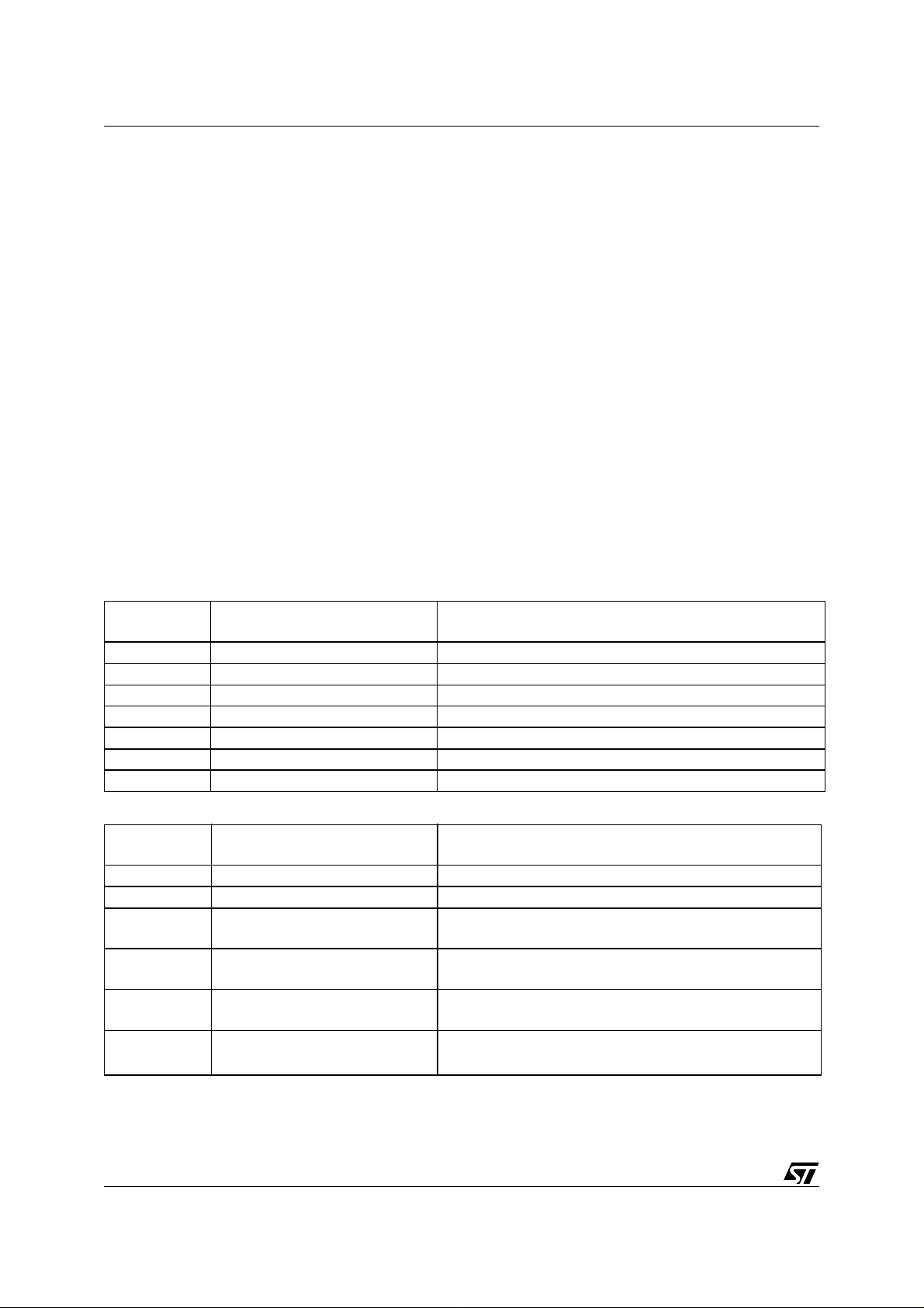
3.4.1.2 Conducted EME Tests
The noise radiated by the microcontroller is caused by the supply current and the output
signal. So, the most significant conducted emission measurements consists of analysing
these signals with a spectrum analyser.
Two probes are used to extract the signal and to adapt the im pedance to t he sp ectrum ana lyser input.
Figure 1. Ground Current Probe
V
ss
Coax cable (= 50
49
Ω
1
Ω
Ω)
to Spectrum Analyser
The 1-ohm resistor is inserted into the main GND wire, i.e. between the power supply, decoupling capacitor and pin load on one side and the IC GND and oscillator load on the other.
Figure 2. Output Signal Probe
OSCIN
OSCOUT
V
SS
1
Ω
V
DD
100µF
A good correlation can be found between radiated EME and ground current measurements.
The 1-ohm probe has very good high frequenc y (HF) characteristics up to 1 GH z. Due to low
signal levels, an amplifier is used.
Output Pin Probe
The HF res ista nce o f wir es o n a pplicat ion b oards is ty pic ally in the ran ge of 100-3 00 ohms.
Therefore, the MCU can be seen as a noise generator connected to a 150-ohm antenna
system. These definitions are taken from standard IEC 1000-4-6. To convert the 150-ohm
board load to 50 ohms, a voltage divider is used.
9/14
Page 10
EMC GUIDELINES FOR MICROCONTROLLER-BASED APPLICATIONS
Figure 3. Voltage Divider Diagram
2 Noise Sources
~
MCU Schem a
120
47 nF
Ω
50
51
Voltage Di vider Spectrum A nalyser
Ω
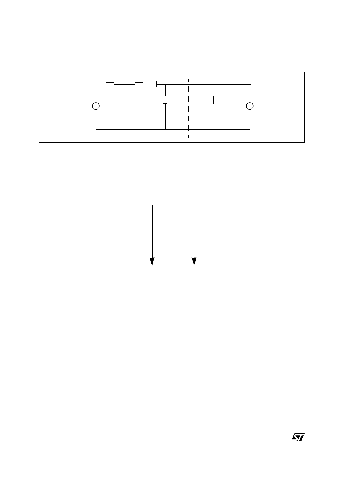
3.4.2 EME Immunity Tests
There are an infinite number of disturbances, but the principal types can be classified according to their spectrum.
Figure 4. Disturbance Spectrum Diagram
Energy
- ESD
- Fast transient
- Radio Frequency
- Surge
- Discontinuity of
the power supply
Rise time
1 ns
5 ns
30-1000 MHz
1.2 µs
in ms
The discontinuity of the power supply is irrelevant since electrical energy is not stored in
MCUs.
The Surge test does not affect the microcontroller as long as the supply voltage remains correct since the rise time is much greater when compared to the clock period.
STMicroelectronics focuses it efforts on ESDs and fast transients.
3.4.2.1 Electrostatic Discharges
Electrostatic dischar ge (ESD) tes ts, i n com pliance with s tanda rd IE C 1000 -4-2, are ver y im portant to ensure that the application is not disturbed by the high amount of static voltage produced by the human body.
There are two types of tests; air-discharge tests that use a spherical tip and contact discharge
tests that use a conical tip.
For contact discharge tests, the tips are placed on the pins and the ESD voltage is in the
0-8 kV range.
10/14
Page 11

EMC GUIDELINES FOR MICROCONTRO LLER-BASED APPLICATIONS
For air-discharge tests, the product is placed on a gr ound plane separated with 10 cm of i nsulation.
Discharges are made on the ground plane.
A statistical method gives more reproducible results.
3.4.2.2 Fast Transients
This test consists of coupling these disturbances to the power supply or to the I/O of the MCU.
Fast transients are generated by switches or relays.
Fast transients are described in standard IEC.1000-4-4.
Figure 5. Disturbance Diagram
100 ns
300 ns
0.9
0.1
0.5
3
50ns
5ns
The spike frequency is 5 kHz. The generator produces bursts of spikes that last 15 ms every
300 ms.
The fast transients are coupled to the device under test (DUT) with capacitors C
. An attenu-
C
ator must be used because the burst generators are too powerful to be directly applied to the
components.
Figure 6. Coupling Network
C
c
To Power Supply
Decoupling Network Power Supply Network
mm
mm
C
c
The fast transients are coupled to the I/O with a small capacitor.
To the DUT
11/14
Page 12

EMC GUIDELINES FOR MICROCONTROLLER-BASED APPLICATIONS
Test Description
The test is performed in compliance with standard IEC 1000-4-4.
Measurements are performed on a ground plane.
The generator is connected to ground plane by a short wire.
The HT wire is 10 cm from the ground plane.
The DUT is on the insulator 10 cm from the ground plane.
The first method consists of increasing the generator voltage until the MCU fails. If this method
demons trates r eprodu cibil ity prob lems (th e volta ge is low er than when the spike occurs ), a
statistical method must be used.
3.4.2.3 Radio Frequency Interference
The radio frequency is a sine wave modulated with a 1-kHz signal. The frequency range is between 150-kHz and 1-GHz. In general, radio frequency interference (RFI) results from electromagnetic radiation. Both radiated and conducted EME tests (described in SAE and VDE specifications, respectively) are used by STMicroelectronics. The first gives a global description of
the MCU whereas the second gives a description of each pin.
The radiated EME tests are performed in a screened room. The DUT is completely isolated by
using special board according to standard SAE 1752.
The test is performed in compliance with standard IEC 1000-4-3.
The conducted EME test uses a coupling network similar to the one used for fast transients.
For each fr equency , the v oltage is increas ed until the M CU fails i n order to c haracter ize the
voltage/frequency interval of safe operation.
3.4.3 Interpretation of Results
The purpose of the described EMC measurements is to gui de the Appl ication Engineer duri ng
EMC d ebuggi ng p hases and f or the p re-qua l ificat ion EM C t es t. Sin ce t hes e m e asurem ent s
are not certified tests, which are the responsibility of specialized laboratories, there is no absolute acceptance levels (which depend on the area of application). This process is designed
to detect EME peaks and sensitive frequencies that exceed accepted levels and in fixing these
defects.
12/14
Page 13

EMC GUIDELINES FOR MICROCONTRO LLER-BASED APPLICATIONS
4 CONCLUS ION
The purpose of this application note i s to convince designers of microcontroller applications to
take EMC performances into consideration at the very beginning of the project.
Most of the EMC improvements presented in this document are already known, but they must
be applied. There is no single action to meet EMC performance requirements, as each technique yields a small improvement. Only a comprehensive application of the techniques mentioned can lead to optimum EMC performances. ST Microelectronics, which has acquired extensive EMC expertise for their microcontrollers, makes their expertise available to their customers.
13/14
Page 14

EMC GUIDELINES FOR MICROCONTROLLER-BASED APPLICATIONS
“THE PRESENT NOTE WHICH IS FOR GUIDANCE ONLY AIMS AT PROVIDING CUSTOMERS WITH INFORMATION
REGARDING THE IR PRO DUCT S IN OR DER FO R THEM TO SAV E TIME . AS A RES ULT, STMIC ROEL ECTR ONI CS
SHALL NOT BE HELD LIABLE FOR ANY DIRECT, INDIRECT OR CONSEQUENTIAL DAMAGES WITH RESPECT TO
ANY CLAIMS ARISING FROM THE CONTENT OF SUCH A NOTE AND/OR THE USE MADE BY CUSTOMERS OF
THE INFORMATION CONTAINED HEREIN IN CONNEXION WITH THEIR PRODUCTS.”
Information furnished is believed to be accurate and reliable. However, STMicroelectronics assumes no responsibility for the consequences
of use of such information nor for any infringement of patents or other rights of third parties which may result from its use. No license is granted
by implic ation or otherwise under any patent or patent ri ghts of STM i croelectr oni cs. Specifications mentioned in thi s publicati on are subject
to change without notice. This publication supersedes and replaces all information previously supplied. STMicroelectronics products are not
authorized for use as cri tical comp onents in life support dev i ces or systems wi thout the express written approv al of STMicroel e ctronics.
The ST logo is a registered trademark of STMicroelectronics
2000 STMicroelectronics - All Rights Reserved.
Purchase of I
Australi a - Brazil - China - Finland - France - Germany - Hong Kong - India - Italy - Japan - Malaysia - Malt a - Morocco - Singapore - Spain
2
C Components by STMicroelectronics conveys a license under the Philips I2C Patent. Rights to use the se components in an
2
C system i s granted pro vid ed that the sy stem conforms to the I2C Standard Specification as defined by Philips.
I
STMicroelectronics Group of Compan i es
Sweden - Switzerland - United K i ngdom - U.S. A.
http://www.s t. com
14/14
 Loading...