

Page 1
AN898
APPLICATION NOTE
EMC GENERAL INFORMATION
by Microcontroller Division Applications
INTRODUCTION
Because many electronic circuits are in proximity to each other, it is essential that their design
is not aff ected by e xterna l noi se so urce s and t hat the circ uit its elf is not a no ise s ourc e affecting other circuits. This relationship is known as electromagnetic compatibility or EMC.
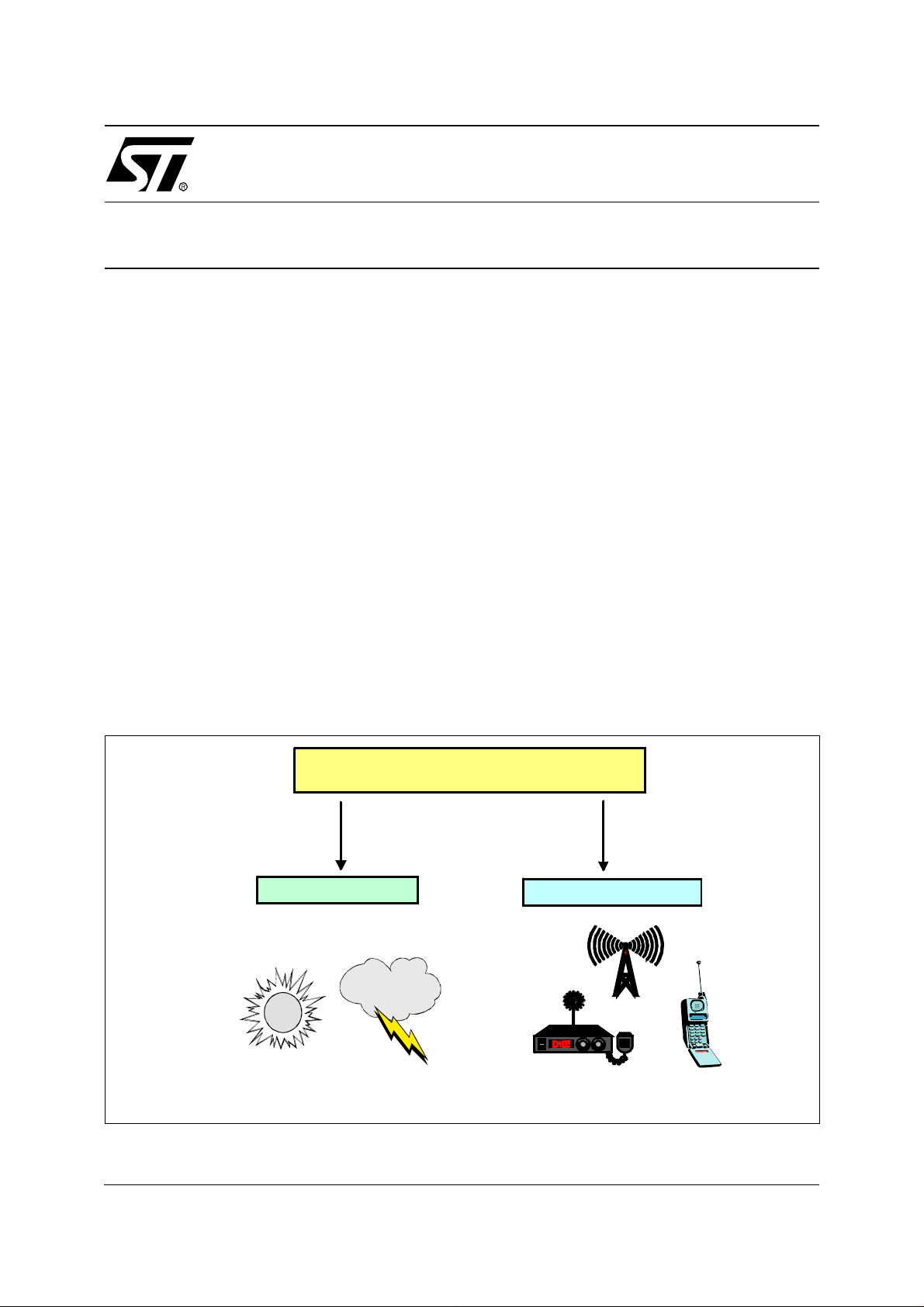
Sources of electromagneti c noise are numerous and have both natural and man-made ori-
gins.
Natural sources below 10 MHz are dom inated by the atmospher ic noise genera ted by electrical storms. Above 10 MHz, natural sources consist primarily of cosmic noise and solar radiation.
Man-made noise include AM, FM, TV and other broadcast transmitters, mobiles radios but
also computing devices, mo tors, appliances, power line s, auto ignition systems and m any
others. W ith the p rolife ration of t hese sour ces (p arti cula rly in u rban area s ), e lect romag net ic
noise has reached important levels.
For detailed information regarding EMC guidelines for microcontroller - based applications,
please refer to AN901.
Figure 1. Electromagnetic Radiation Sources
ELECTROMAGNETIC RADIATION
NATURAL ORIGIN
M A N-M A DE ORIGIN
VR02102A
AN898/1100 1/4
1
Page 2
EMC GENERAL INFORMATION
1 EMI AND EMS
Almost every electronic device emits some electromagnetic interferen ce (EMI). These
emissions can be transm itted as electromagnetic radiation or conducted through cables
such as power cords. At the s ame time, most el ectronic devi ces are s usceptible to emissions
generated either internally or by other devices.
Receptors susceptible to electromagnetic radiation include communication receivers such as
radio and television, radar and navigation devices or computing devices. The effect of the interference on the receptor depends on several parameters: strength of the source, transmission medium, distance from the source, coupling mechanisms and degree of susceptibility of
the medium.
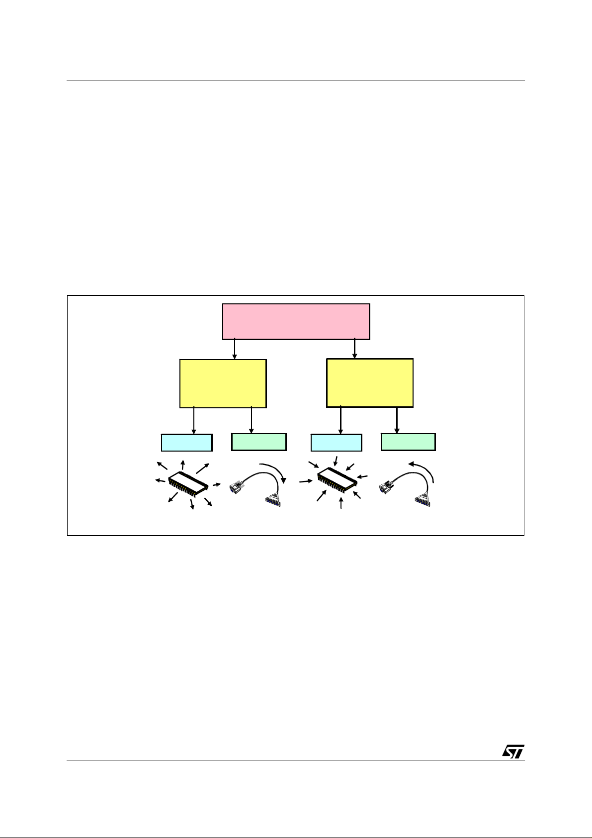
Figure 2. EMC Contents: EMI and EMS
EMC
Electromagnetic Compatibility
EMS
Electromagnetic
S u s c eptibility
Conducted
VR02102B
Electromagnetic
Radiated
EMI
Int e rfe re n c e
Condu cted
Radiated
Electromagnetic interference (EMI) tests involve measuring the frequency and amplitude of
undesirable signals emitted by the tested equipment. Signal radiated into free space are
called radiated emissions, whereas signa ls trave lling a long p ower cords or other int erconnecting cables are called conducted emissions.
Electromagnetic susceptibility ( EM S) testing is a way to determine the ability of the device
to operate properly in an undesirable electromagnetic environment. These tests use signal
sources and power am plifiers to gene rate high level fi elds aroun d a dev ice. Co nducted s usceptibility me as urem ent s are p erfo rmed by co upling an o ffe nding si gnal o f a s pe cified le vel
onto cables to try to induce a malfunction into the tested device. Other forms of susceptibility
tests include electrostatic discharge (ESD), transient burst and voltage surge testing.
2/4
2
Page 3

EMC GENERA L INFORMATION
2 EMC REGUL ATI ONS
Regulations are one of the primary reasons we test products for EMC. Therefore, we will now
look at some of the important organizations that develop and enforce EMC regulations. Failing
to comply with EMC regulations can result in forced removal of a product from the market
place or even monetary fines.
Figure 3. Conducted versus radiated Regulations
FCC
Federal
Com munications
Com m ission
EN
European Norms
MIL-STD
US Military
Norms
Frequency (Herz)
VR 02102C
CONDUCTED
RADIATED
9 KHz
30 Hz
30 Hz
1 Hz 1 kHz
450 kHz
9 kHz
FCC
EN
MIL-STD
30 MH z
EN
MIL-STD
1 MH z
30 MH z
30 MH z
FCC
40 G Hz
40 G Hz
1 GHz
40 G Hz
1 GH z
EMC regulations cover the entire spectrum of electrical products, from computing equipment
to microwave ovens to aircraft. As shown, the frequency ranges of interest for EMC testing extend from 30 Hz to 40 GHz (9 orders of magnitude), depending on the agency and the type of
measurement. The frequency range over which regulations exist varies, depending on the device and its intended use.
While individual EMC requirements vary widely from one another , one common aspect is the
goal of achieving valid, repeatable results. Therefore, most regulations specify the test environment, receiver and transd ucer characteristics. An tenna height and polarization is usua lly
varied, and the tested equipment is rotated to find the maximum response from the device. All
these actions help insure that the worst-case emissions are found.
Because so ma ny factors a ffect emi ssions, an environmen t wi th know n cha racteri stics mu st
be used when measuring electromagnetic interference. Testing within a k nown environment is
critical in ord er to ass ure mean ingful and rep eatab le results th at ca n be compa red to other
measurements performed on other devices.
3/4
Page 4

EMC GENERAL INFORMATION
“THE PRESENT NOTE WHICH IS FOR GUIDANCE ONLY AIMS AT PROVIDING CUSTOMERS WITH INFORMATION
REGARDING THE IR PRO DUCT S IN OR DER FO R THEM TO SAV E TIME . AS A RES ULT, STMIC ROEL ECTR ONI CS
SHALL NOT BE HELD LIABLE FOR ANY DIRECT, INDIRECT OR CONSEQUENTIAL DAMAGES WITH RESPECT TO
ANY CLAIMS ARISING FROM THE CONTENT OF SUCH A NOTE AND/OR THE USE MADE BY CUSTOMERS OF
THE INFORMATION CONTAINED HEREIN IN CONNEXION WITH THEIR PRODUCTS.”
Information furnished is believed to be accurate and reliable. However, STMicroelectronics assumes no responsibility for the consequences
of use of such information nor for any infringement of patents or other rights of third parties which may result from its use. No license is granted
by implic ation or otherwise under any patent or patent ri ghts of STM i croelectr oni cs. Specifications mentioned in thi s publicati on are subject
to change without notice. This publication supersedes and replaces all information previously supplied. STMicroelectronics products are not
authorized for use as cri tical comp onents in life support dev i ces or systems wi thout the express written approv al of STMicroel e ctronics.
The ST logo is a registered trademark of STMicroelectronics
2000 STMicroelectronics - All Rights Reserved.
Purchase of I
Australi a - Brazil - China - Finland - France - Germany - Hong Kong - India - Italy - Japan - Malaysia - Malt a - Morocco - Singapore - Spain
2
C Components by STMicroelectronics conveys a license under the Philips I2C Patent. Rights to use the se components in an
2
C system i s granted pro vid ed that the sy stem conforms to the I2C Standard Specification as defined by Philips.
I
STMicroelectronics Group of Compan i es
Sweden - Switzerland - United K i ngdom - U.S. A.
http://www.s t. com
4/4
 Loading...