

Page 1

AN887
APPLICATION NOTE
MICROCONTROLLERS MADE EASY
by Microcontroller Division Applications
WHAT IS A MICROCONTROLLER?
A few years ago, system control functions were impleme nted using logic components and
were usu ally lar ge, heav y box es. Lat er on, microp roce ssors were us ed an d the ent ire con troller could fit onto a small circuit board. As the process of miniaturization continued, all of the
components needed for a controller were built right onto one chip. By only including the features specific to the task, cost is relatively lo w.
A typical microcontroller has bit manipulation instructions, easy7 and direct access to I/O, and
quick and effi cient int errupt pr ocessi ng. There fore, a m icroc ontroller is a highly integrated
device which includes, on one ch ip, all or most of the parts needed to perform an application
control function.
Microcontrollers come in many varieties. D epending on the power and features that are
needed, customers might choose a 4, 8, 16, or 32 bit microcontroller.
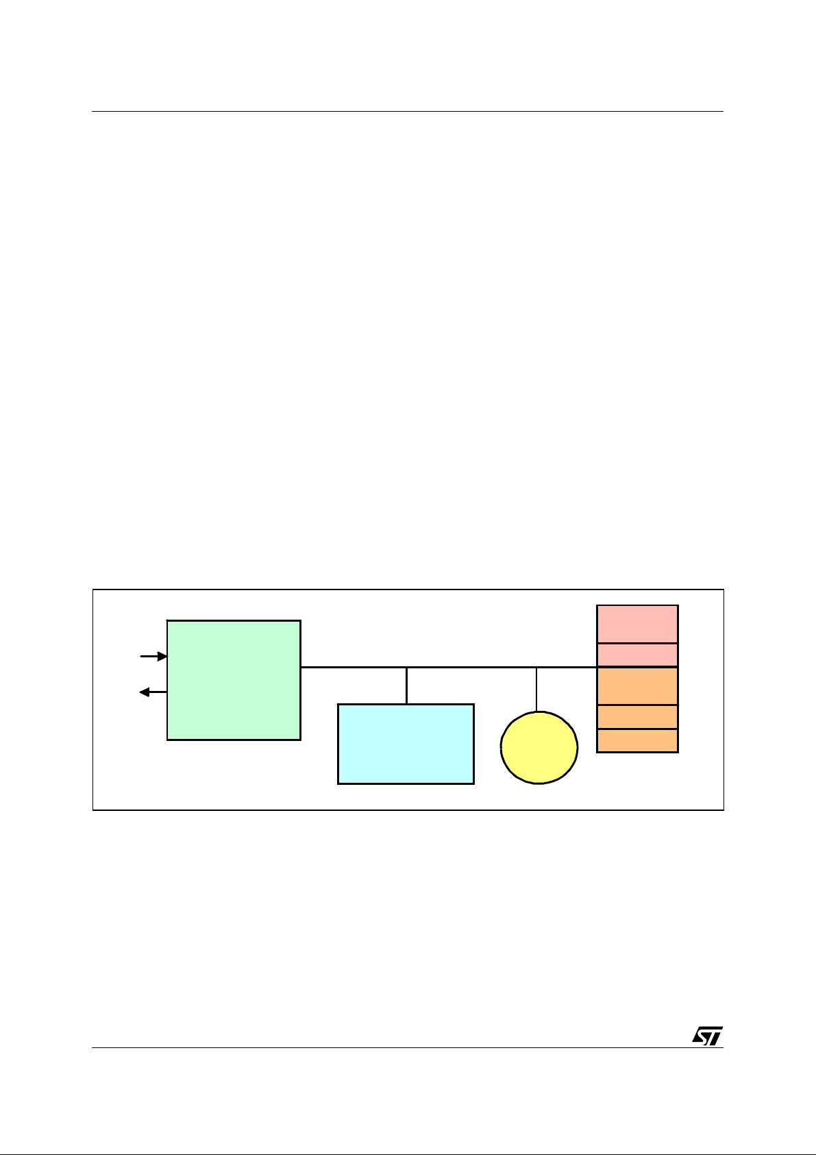
Figure 1. Typical MCU Block Diag ram
CONTAINS
PROGRAM
AND DATA
EXECUTES PROGRAM
MANAGES EVENTS
SIGNAL GENERATION
EVENT COUNTING
APPLICATION TIMEBASE
PERIPHERAL
INTERFACE
ROM
CPU
TIMER
I/O P OR T
RAM
EEPROM
A / D
CONVERTER
SERIAL
INTERFACE
CONTAINS
TEMP ORARY
DATA
CONTAINS
PERMANENT
DATA
ANALOG DATA
ACQUISITION
SENDS AND
RECEIVES
DATA
VR02101A
ROM (Read Only Memory)
ROM is usually used to store program instructions. RO M is the l east expensive mean of
storing a program in a microcontroller, especially for high volume manufacturing.
AN887/1100 1/12
1
Page 2
MICROCONTROLLERS MADE EASY
Flash
Flash is an electrically erasable and programmable memory. It can be used instead of ROM to
store program instructions and data. A key parameter of F lash memory is i ts enduranc e or the
number of times it can be erased or reprogrammed. Depending on the technology used, flash
endurance can be either 100 or 300,000 program/erase cycles.
RAM (Random Access Memory)
During in the e xec ution o f a prog ram, d ata ha ve to be sav ed for la ter use. D ata a re u sual ly
stored in RAM.
EEPROM (Electrically Erasable Programmable Read Only Memory)
There is anothe r way to store data in a microcon troller : EEPRO M is used to sto re data that
must be saved through a power down cycle.
CPU (Central Processing Unit)
It is the brain of the system that processes all data and their travel along the bus. For example,
in order to e xecute a program , th e C PU will re ad th e f irst i nstruct ion from pr ogram mem o ry.
This instruction is decoded by t he C PU a nd exec ute d. At the co mpletio n o f the e xec ution of
the instruction, the next instruction is fetched from memory and is executed. This pr ocedure is
repeated until the end of the program (or an endless loop) is found.
Figure 2. Typical Microcontroller Block Organization
PROGRAM
INPUT
OUTPUT
PERIPHERAL
SYSTEMS
BUS
CENTRAL
PROCESSING
TIMING
SYSTEM
MEMORY
ROM
DATA
MEMORY
RAM
EEPROM
UNIT
VR02101B
TIMERS
The timer or timing system makes it poss ible to measure and time external and internal
events. The power of the timers varies greatly between different MCUs.
I / O (INPUT / OUTPUT) PORTS
Most microcontrollers have several digital I/O ports that are used to drive a LED or get a keyboard input. Usually, a port consists of eight or l ess bi ts, usually programmable as either i nput
or output bits.
2/12
2
Page 3
MICROCONTROLLERS MADE EASY
SERIAL INTERFACE
Serial interface are used to exchange data with the external world. Many microcontrollers
have both asynchronous and synchronous communications peripherals built in. Usually, an
asynchro nous interfa ce is cal led a se rial com munic ation interfac e (SCI or UART) while the
synchronous interface is called a serial peripheral interface (SPI). A typical SCI application is
to conne ct a PC for debu gging pu rpose while a t ypical SPI appl icatio n is to co nnect an external EEPROM.
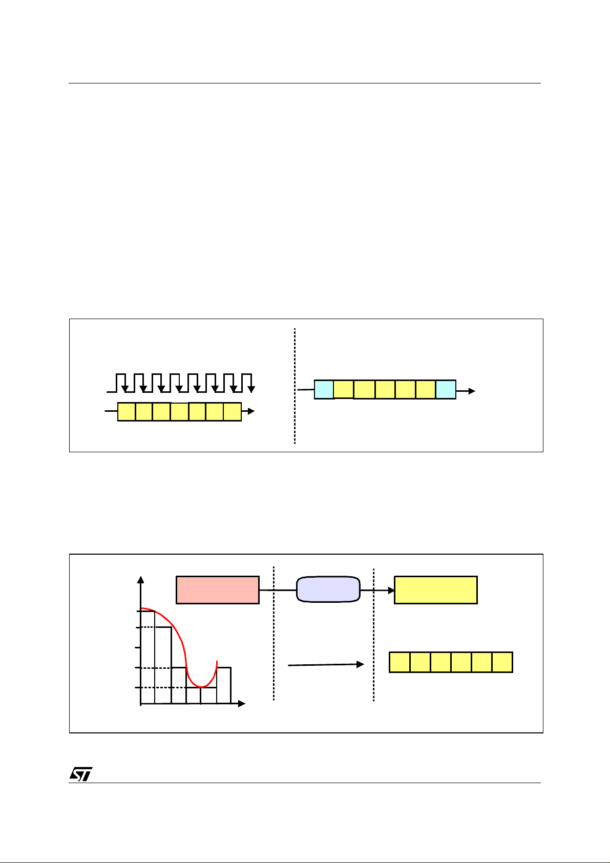
A synchronous bus includes a separate line for the clock signal which simplifies the transmitter
and receiver but is more susceptible to noise when used over long distances. With an as ynchronous bus the transmitter and receiver clocks are independent, and a resynchronization is
performed for each byte at the start bit.
Figure 3. Synchronous and Asynchronous Communication Principles
SYNCHRONOUS
CLOCK
bbb
b b
bb
DATA
0b bbb
Start
ASYNCHRONOUS
b1
Stop
CLOCK
+
DATA
VR02101C
A/D CONVERTER
Converts an external analog signal (typically relative to voltage) into a digital representation.
Microcont rollers that have th is featu re can be used fo r instrume ntation , envir onmen tal data
logging, or any application that lives in an analog world.
Figure 4. A/D Converter Principle
Voltage
ANALOG
5
4
3
2
ANALOG
SIGNAL
A / D
CONVERTER
DIGITAL
54
2
11
2
1
Time
VR02101D
3/12
Page 4
MICROCONTROLLERS MADE EASY
1 TYPICAL MICROCONTROLLER APPLI CATIONS
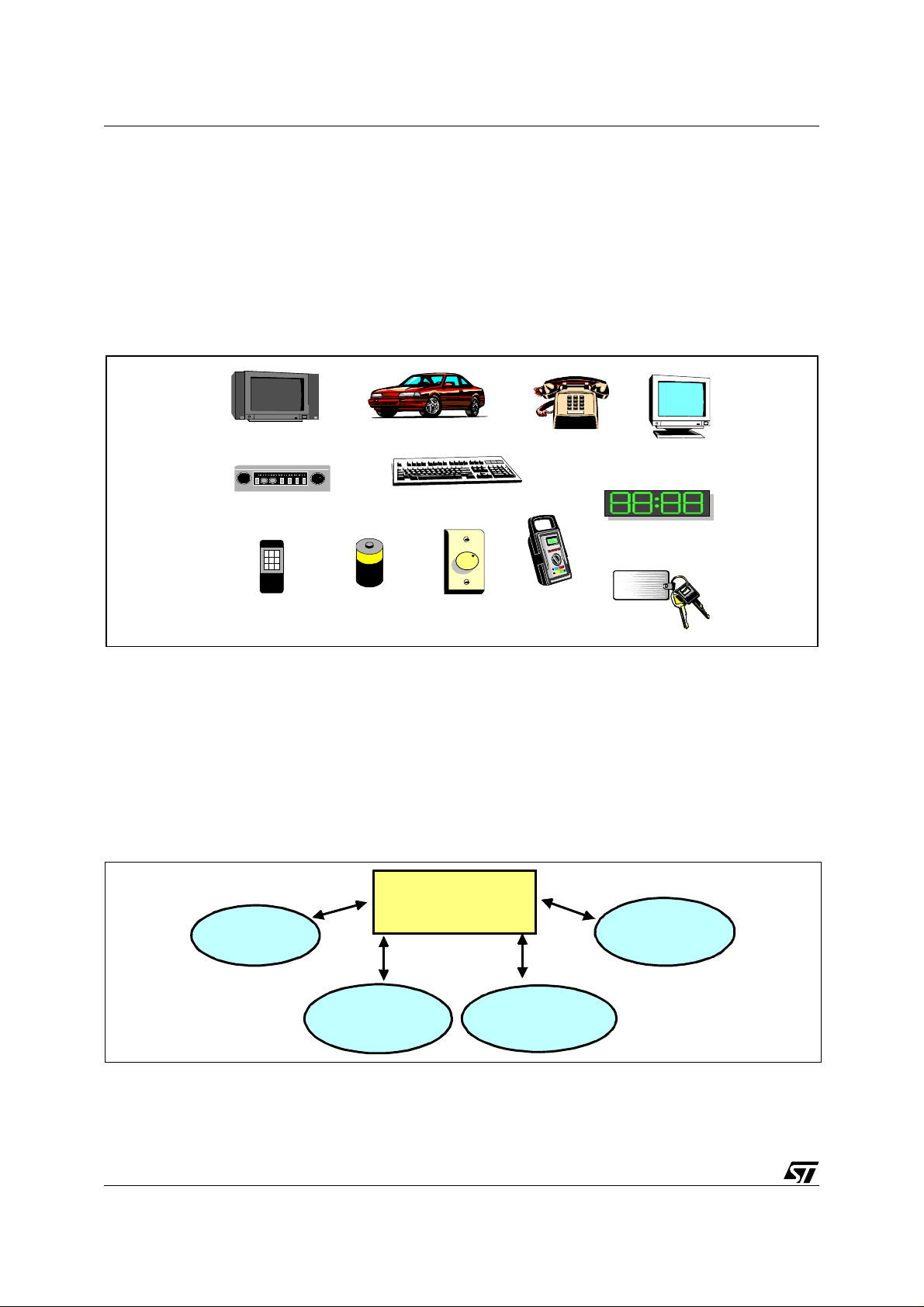
Microcontrollers are frequently found in home appliances (microwave oven, refrigerators, television and VCRs, stereos), computers and computer equipment (laser printers, modems,
disk drives), cars (engine control, diagnostics, climate control), environmental control (greenhouse, factory, home), instrumentation, aerospace, and thousands of other uses. In many
items, more than one processor can be found.
Figure 5. Typical MCU Applications
TV SET
CAR RADIO
REMOTE
CONTROL
BATTERY CHARGER
BODY CONTROLLER
KEYBOARD
DIMMER
SWITCH
TELEPHONE SET
REMOTE
METER
MONITOR
DASHBOAD
FRONT PANEL
KEYLESS
While microproc essors targe t the maximu m proces sing performa nce, the pur pose of micro controllers is to impl ement a se t of control functi on in the most cos t effective w ay. Although
(TM)
controlling a microwave oven with a Pentium
might seem an attractive idea, it can be easily
accomplished with an ST6.
In a typical application, the MCU has to manage several tasks according to their priority or to
the occurrence of external events (new command send by the keyboard, external temperature
rise,...)
Figure 6. Example of MCU Task Management.
CENTRAL MCU
KEYBOARD
SCANNING
MEASURE
TEMPERATURE
FUN CTIO N
CHANGE
TEMPERATURE
INFORMATION
DISPLAY
VR0 2101E
The ability to manage control tasks by hardware or by software is the mai n performance indicator for MCUs.
4/12
Page 5

MICROCONTROLLERS MADE EASY
EXAMPLE: THE AUTOMOTIVE MARKET
The autom otive market is the m ost importan t single driving force in the microcontroller
market, especially at it’s high end. Several microcontroller families were developed specifically
for automotive applications and w ere subsequently mo dified to s erve other embedded a pplications.
Figure 7. MCU Applicatio ns in Automotive
FUEL INJECTION
WIND OW LIFT
CAR RADIO
TRIP COMPUTER
DASHBOARD DISPLAYSEAT BELT FASTENER
KEYLESS ENTRY
AIRBAG
VR02101F
VR02101F
The automotive market is demanding in term of device performance and component reliability.
Electronics must operate under extreme temp eratures and be abl e to withstan d vi bration,
shock, and EMI. T he electronics must be reliable, because a failure that causes an accident
can (and does) result in multi-million dollar lawsuits. Reliability standards are high - but because these electronics also compete in the consumer market - they have a low price tag.
Figure 8. MCU Applications in Today’s and Tomo rrow’s Home
TOD AY’S
HOME
- TV SET, VCR
- CORD LESS PHONE
- W A S H IN G MAC H IN E
- VACUUM CLEANER
TOM ORR OW ’S
HOME
- ENERGY MANAGEMENT
- HOME AUTOMATION
- HEATING SYSTEM
- "GREEN " RE FRIGERAT O R
- SECURITY
VR02101G
5/12
Page 6
MICROCONTROLLERS MADE EASY
2 ADDITIO NAL MICROCO NTROLLER FEATURES
2.1 TIMERS
Watchdog timer. A watchdog timer provides a me ans of graceful recovery from a system
problem. This could be a program that goes into an endless loop, or a hardware problem that
prevents the pr ogram from operating c orrectly. If the program fai ls to reset th e watchd og at
some predetermined interval, a hardware reset will be initiated. The bug may still exist, but at
least the system has a way to recover. This is especially useful for unattended systems.
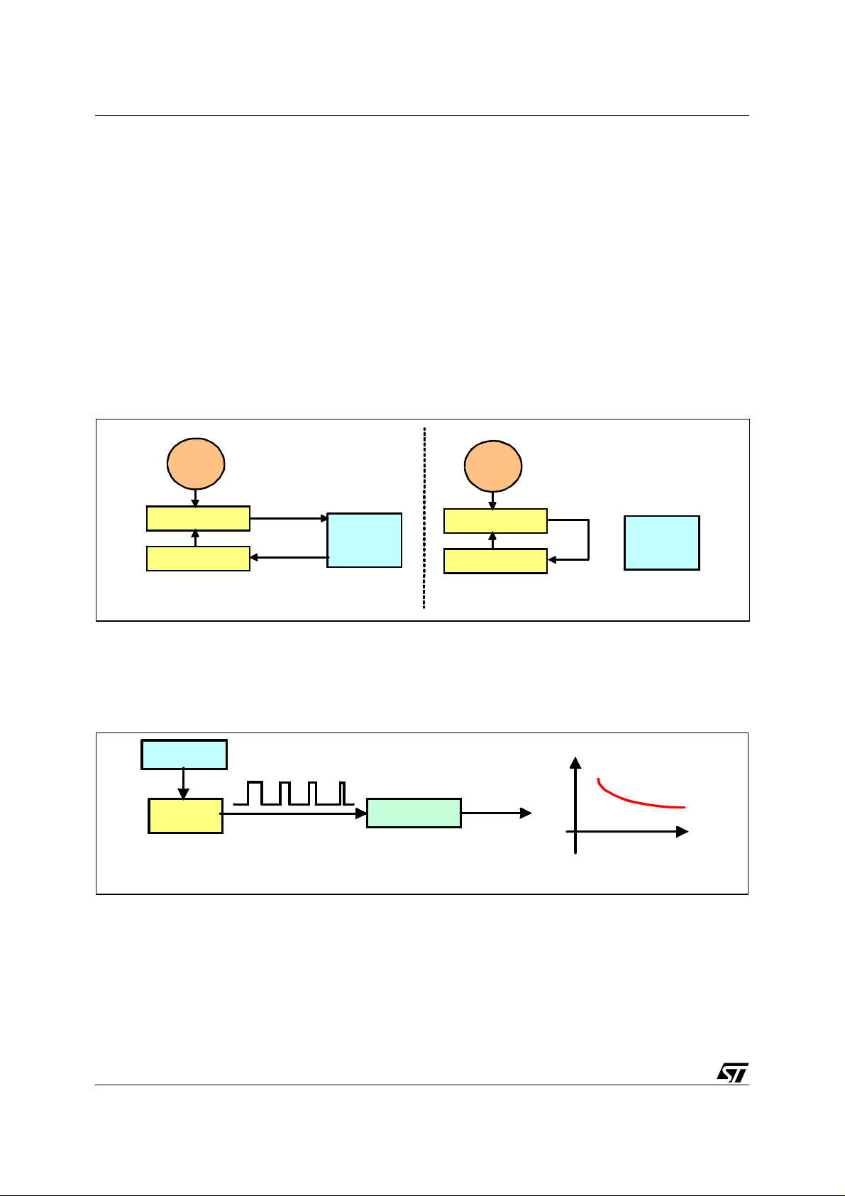
Auto Reload Timer. Com pared to a stan dard timer, th is timer au tomatical ly reloads its
counting value when the count is over, therefore sparing a waste of CPU resource.
Figure 9. Standard Timer and Auto-Reload Timer Principle
AUTO RELOAD TIMER
End of
Count
CPU
Reload
VR02101H
CLOCK
TIMER
Load Register
STANDARD TIMER
CLOCK
End of
Count
TIMER
CPU
Load Register
Reload
Pulse Width Modulator. Often used as a digital-to-analog conversion technique. A pulse
train is generated and regulated with a l ow-pass filter to generate a vol tage proportional to the
duty cycl e.
Figure 10. PWM Principle
CLOCK
PW M
V
RC Filter
ANALOG
VOLTAGE
time
VR02101I
Pulse A ccum ula tor. A pu lse a ccumu lato r is a n even t cou nte r. Each pul se incr em ents th e
pulse accumulator register, recording the number of times this event has occurred.
Input Capture. Input Capture can measure external frequencies or time intervals by copying
the value from a free running timer into the input capture register when an external event occurs.
6/12
Page 7

MICROCONTROLLERS MADE EASY
Output Compare. Output C ompare can time an external ev ent by sending a value stored in-
side the output compare register.
Figure 11. Input Capture and Output Capture Timer Functions
INCOMING
EVENT
OUTGOING
EVENT
value
value
INPUT CAPTU RE
TIMER
IC register
OUTPUT COMPARE
TIMER
OC register
CLOCK
CLOCK
VR021 01J
2.2 DIGITAL SIGNAL PROCESSORS (DSP)
Microcontrollers react to and control events, whereas DSPs execute repetitive math-intensive
algorithms. Today many embedded applications require both types of processors, and semiconductor ma nufacture rs have respon ded by introduc ing microcon trollers w ith on-chip DS P
capability and DSPs with on-chip microcontrollers.
The most basic thing a DSP will do is a MACC (Multiply and ACCumulate). The number of
data bits a DSP c an Multiply and ACCum ulate will determine the dy namic range (and t herefore the application).
2.3 ANALOG AND DIGITAL SIGNALS
We live in an analog world where the information we see, hear, process, and exchange with
each other, and with our mechanical and electronic systems, is always an analog quantity:
pressure, temperature, voltage and current are always analog entities. They can be digitized
for more efficient sto rage and trans mission, but the int erface ( input an d ou tput) is alm ost always analog. Thus the essence of analog electronics lies in sensing continuously varying information, converting it to digi tal and reshaping the digital data to an analog signal at the other
end. Mixed analog-digital devices are being used increasingly to integrate the complex functions of high-speed telecommunications, or the real-time data processing demanded by industrial control systems and automotive systems.
7/12
Page 8

MICROCONTROLLERS MADE EASY
Figure 12. Mixed A/D System Example
ANALOG
DATA
THERMOMETER
A / D
CONVERTER
DIGITAL
DATA
PROCESSING
D / A
CONVERTER
ANALOG
DATA
FAN
VR02101K
Analog to digital conversion (A / D). Converts an external analog signal (typicall y relative to
voltage) and converts it to a digital representation. Microcontrollers that have this feature can
be used for instrumentation, environmental data logging, or any application that lives in an analog world. Various types of A/D converters that can be found.
Comparator. O ne or mor e stan dard com parator s c an so meti mes be pl aced on a mi crocon troller die. These comparators operate much like standard comparators however the input and
output signals are available on the microcontroller bus.
Digital to analog conversion (D/A). This feature takes a Digital number and converts it to a
analog output. The number 50 would be changed to the analog output of (50 / 256 * 5 Volts)
= .9765625 V on a 8 bit / 5 Volt system.
8/12
Page 9

MICROCONTROLLERS MADE EASY
2.4 COMMUNICATION
CAN & J1850
CAN (Controller Area Network) is a m ultiplexed wiring scheme that was developed jointly by
BOSH and Intel for wiring in automobiles. J1850 is the SAE (Society of Automotive Engineers)
multiplexed automotive wiring standard that is currently in use in North America.
The CAN specification seems to be the one that is being used in industrial control both in
North American a nd Eur ope. With l ower c ost mi crocontrollers that sup port CA N, C AN has a
good potential to take off.
Figure 13. CAN Principle
INT E R
SYSTEM
Motor
ABS / ASR
Dashboard
Fuse Box
Air Conditioner
FAST
SPEED
> 125 Kb / s
GATEWAY
SLOW
SPEED
< 1 2 5 Kb / s
SLOW
SPEED
COMFORT
Radio, Display
Navigation
System, Phone
BODY
W indow, Lock
Se a t, Lam p s
VR02 101L
I2C BUS - Inter-Integrated Circuit Bus (PHILIPS)
The I2C bus is a simple 2 wire serial interface developed by Philips. It was developed for 8 bit
applicati on s a nd is w idel y u s ed i n con s ume r e lec tro nic s, a ut om oti ve an d ind us trial ap pli cations. In addition to microc ontrollers , several per ipherals a lso ex ist t hat suppo rt the I2C bu s.
The I2C bus is a two line, multi-master, multi-slave network interface with collision detection.
Up to 128 devices can exist on the network and they can be spread out over 10 meters. Each
node (microcontroller or peripheral) may initiate a message, and then transmit or receive data.
The two lines of the network consist of the serial data line and the serial clock line. Each node
on the network has a unique address which accompanies any message passed between
nodes. Since only 2 wires are needed, it is easy to interconnect a number of devices.
UART. A UART (Universal Asynchronous Receiver Transm itter) is a serial port adapter for
asynchronous serial communications.
USART. A U SART (Universal Synchronous / Asynchronous Receiver Transmitter) is a serial
port adapter for either asynchronous or synchronous serial communications. Communications
using a USART are typically much faster (as much as 16 times) than with a UAR T.
9/12
Page 10

MICROCONTROLLERS MADE EASY
2.5 INTERRUPTS
Polling. Polling is what you have to do if your microcontroller does not have interrupts or if
what you want to do is not time critical. It is a software technique whereby the controller continually asks a peripheral if it needs servicing. The peripheral sets a flag when it has data
ready for transferring to the controller, whi ch the controller noti ces on its next poll. Several peripherals can be polled i n succession, with the controller jumping to differ ent software routines,
depending on which flags have been set.
Figure 14. Polling versus Interru pt
POLLING
TASK 1
POLLING LO O P
TASK 2
POLLING LOOP
TASK 3
Event occurs
POLLING LOOP
TASK 4
PROCESS
EVENT
INTERRUPT
TASK 1
TASK 2
TASK 3
Event occurs
TASK 4
INTERRUPT
Save State
PROCESS
EVENT
Restore State
VR0210 1M
Interrupts. Rather than have the m icroc ontroll er contin ually poll ing - that i s, askin g peripherals (ti mers / U AR TS / A/ Ds / e xt ern al c om po nen ts) whether th ey hav e an y d ata avai lable
(and finding most of the time they do not), a more efficient method is to have the peripherals
tell the control ler w hen th ey hav e data ready . The co ntrol ler can be ca rrying out its norma l
function, only responding to peripherals when there is data to respond to. On receipt of an interrupt, the controller suspends its curr ent operation, identi fies the interrupting peri pheral, then
jumps to the appropriate interrupt service routi ne. The advantage of interrupts, c ompared with
polling, is the speed of response t o external events and reduced s oftware overhead (of con tinually asking peripherals if they have any data ready).
Most microcontrollers have at least one external interrupt, which can be edge selectable
(rising or fall ing) or l evel trigger ed. Both systems have adv antages. Edge is not time sensitive,
but it is susceptible to glitches. Level must be held high (or low) for a specific duration (which
can be a pain but is not susceptible to glitches).
10/12
Page 11

MICROCONTROLLERS MADE EASY
3 POWER SUPPLY ISSUES IN MCUs
Since automotive applications have been the driving force behind most microcontrollers, and
5 Volts was very easy to do in a car, most microcontrollers only supported 4.5 - 5.5 V operation. In the recent past, as consumer goods were beginning to drive major segments of the microcontroller market, and became portable and lightweight, the requirement for 3 volt (and
lower) m icr ocont rol lers b ecam e u r ge nt. 3 v olt s m eans 2 ba tter y s olut ion, lo we r v olt age and
longer battery life. Most low voltage parts in the market today are simply 5 volt parts that were
modified to operate at 3 volts (usually at a performance loss). Some micros being released
now are designed from th e ground up to operate pr operly at 3.0 (and lower) voltages , whi ch
offer a performance level comparable to 5 volt devices.
But why are voltages going down on ICs? There are a few interesting rules of thumb regarding
transistors:
1) The amount of power they dissipate is proportional to their size. If y ou make a transistor half
as big, it dissipates half as much power.
2) Their propagation delay is proportional to their size. If you make a transistor half as big, it’s
twice as fast.
3) Their cost is proportional to the square of their size. If you make them half as big, they cost
one quarter as much.
Figure 15. Transistor Parameter Scheme
+
SIZE
COST
SUPPLY VOLTAGE
For years people have been using 5 Volts to power integr ated circuits. Because the transistors
were large, there was little danger damaging the transistor putting this voltage across it. However, now that the transistors are getting so small, 5 Volts would now destroy them. The only
way around this is to start lowering the voltage. This is also why people are now using 3 (actually 3.3) Volt logic, and this will certainly lead to lower voltages in the next few years.
TRANSISTOR
-
-
+
SPEED
POWER
VR02101N
11/12
Page 12

MICROCONTROLLERS MADE EASY
“THE PRESENT NOTE WHICH IS FOR GUIDANCE ONLY AIMS AT PROVIDING CUSTOMERS WITH INFORMATION
REGARDING THE IR PRO DUCT S IN OR DER FO R THEM TO SAV E TIME . AS A RES ULT, STMIC ROEL ECTR ONI CS
SHALL NOT BE HELD LIABLE FOR ANY DIRECT, INDIRECT OR CONSEQUENTIAL DAMAGES WITH RESPECT TO
ANY CLAIMS ARISING FROM THE CONTENT OF SUCH A NOTE AND/OR THE USE MADE BY CUSTOMERS OF
THE INFORMATION CONTAINED HEREIN IN CONNEXION WITH THEIR PRODUCTS.”
Information furnished is believed to be accurate and reliable. However, STMicroelectronics assumes no responsibility for the consequences
of use of such information nor for any infringement of patents or other rights of third parties which may result from its use. No license is granted
by implic ation or otherwise under any patent or patent ri ghts of STM i croelectr oni cs. Specifications mentioned in thi s publicati on are subject
to change without notice. This publication supersedes and replaces all information previously supplied. STMicroelectronics products are not
authorized for use as cri tical comp onents in life support dev i ces or systems wi thout the express written approv al of STMicroel e ctronics.
The ST logo is a registered trademark of STMicroelectronics
2000 STMicroelectronics - All Rights Reserved.
Purchase of I
Australi a - Brazil - China - Finland - France - Germany - Hong Kong - India - Italy - Japan - Malaysia - Malt a - Morocco - Singapore - Spain
2
C Components by STMicroelectronics conveys a license under the Philips I2C Patent. Rights to use the se components in an
2
C system i s granted pro vid ed that the sy stem conforms to the I2C Standard Specification as defined by Philips.
I
STMicroelectronics Group of Compan i es
Sweden - Switzerland - United K i ngdom - U.S. A.
http://www.s t. com
12/12
 Loading...