

Page 1

AN863
APPLICATION NOTE
Improved sensorless control with the ST62 MCU
for universal motor
The universal motor is today the most widely used motor in home appliances (vacuum
cleaner, washer, hand tool, food processor...). Three modes of operation exist:
– in many cases, it is directly connected to the mains, without any speed adjustment.
More and more, however, the decreasing cost of electronics allows to include an adjustable
speed drive in the appliance. The control can be open loop or closed loop:
– in open loop mode, the speed is adjusted by the user but not regulated: it decreases when
the load increases. This is the case in many vacuum cleaners for example.
– in closed loop mode, the speed is regulated. This mode is used when the speed must be
accurately kept at a given value, in washers for example. This mode requires to add a speed
sensor on the motor shaft. Such a sensor is usually a tacho generator or magnet sensor.
The drawbacks of the speed sensor are many, but all boil down to higher cost and lower re
liability, not to mention the extra bulk needed to accommodate the sensor inside the plastic
housing of a drill for example.
This document describes a speed regulator without sensor: the speed sensing is performed
indirectly by the ST6220, low-cost 8-bit microcontroller, measuring the motor current. Perform
ance results are given, which are in line with the need of many home appliances.
-
-
June 2008 Rev 2 1/22
1
Page 2

IMPROVED SENSORLESS CONTROL WITH THE ST62 MCU FOR UNIVERSAL MOTOR
Tr
1 UNIVERSAL MOTOR PRINCIPLES
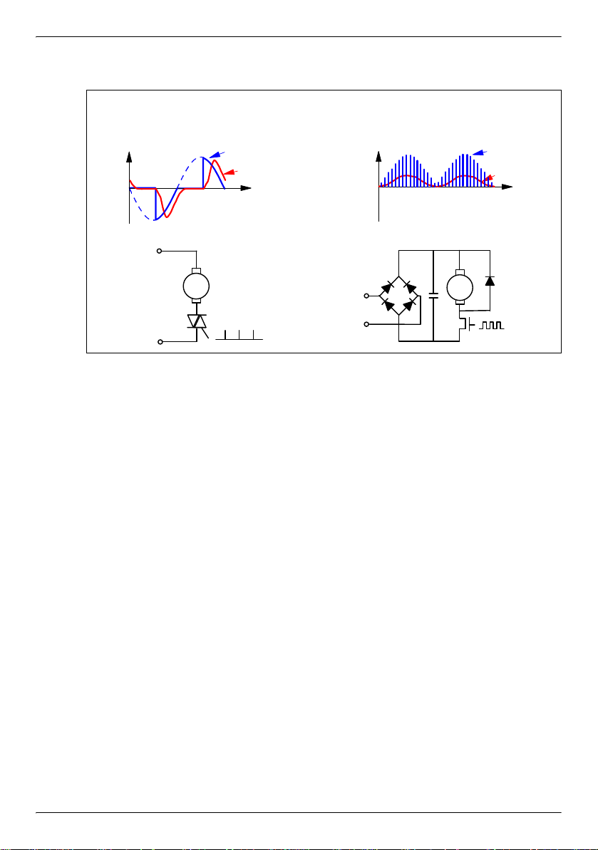
The universal motor can be driven in AC or DC mode. Figure 1 shows the two most
popular variable speed drive principles. The goal is to adjust the voltage seen by the
motor in order to adjust its speed. In AC mode, the motor voltage is adjusted by var
ying the firing delay of a triac. This is done with a diac, resistor and capacitor when
lowest cost is desired, and with an 8 bit micro-controller when higher performance
and added features are desired, such as user interface or monitoring [1]. The switch
is usually a triac, the cheapest power switch.
In DC mode, the motor is supplied by a high frequency pulse width modulated (PWM)
DC voltage. The voltage seen by the motor is proportional to the PWM duty cycle,
which can be adjusted to modify the speed. The power switch used to chop the DC
voltage at high frequency is a power MOS or an IGBT. The DC mode has several ad
vantages versus the AC mode (less acoustic noise, higher efficiency, lower harmonics content, all due to lower current ripple, as is shown in Figure 1). However, in
low cost appliances, the AC mode still dominates due to its lower cost (no rectifier
bridge, no fast diode, triac cheaper than IGBT or MOS). This is the mode we will focus
on in the next pages.
The universal motor is a serial excitation motor. Therefore, the motoring torque is pro-
portional to the square of the motor current: Tm = k. I²
The mechanical power is the product of the torque by the speed: P = Tm.Ω
If we assume 100% efficiency, the mechanical power equals the electrical power V.I
input to the motor. It follows that the speed is proportional to
V/I:
Ω = k'. V / I (V and I are average voltage and current over a mains period). The first
consequence is that the motor speed is proportional to the average motor voltage.
At constant speed, the resistive torque Tr is equal to the motoring torque Tm. It
comes from the previous equations that the speed is given by:
This equation shows that when the resistive load torque increases at a given voltage,
the motor speed will decrease, hence the need for speed regulation. This regulation
can be performed by adjusting the average voltage V.
Ω= k.V / .
-
-
2/22
Page 3
IMPROVED SENSORLESS CONTROL WITH THE ST62 MCU FOR UNIVERSAL MOTOR
AC: PHASE CONTROL
DC: PWM CONTROL
t
Vmotor
Imotor
t
Vmotor
Imotor
M
M
Figure 1. Universal motor variable speed drive: AC versus DC mode
3/22
Page 4
IMPROVED SENSORLESS CONTROL WITH THE ST62 MCU FOR UNIVERSAL MOTOR
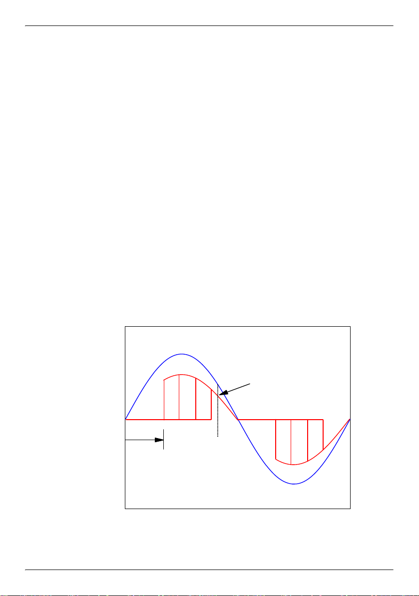
Vmains
Imotor
t
0
td
i(t0)
2 SENSORLESS REGULATION PRINCIPLE
The above equations were first order equations, assuming DC operation, or average
values for voltage and current. The real, instantaneous equation is the following:
While the triac is off:
i = 0
While the triac is on (after firing time td, and until current comes back to zero; see
Figure 2):
v = e + z.i
with: e = back electromotive force (bemf) = k. Ω. i
z = motor impedance = r + j.L.ω
k = constant dependent upon motor characteristics
Ω = motor speed
i = instantaneous motor current
v = instantaneous motor voltage
L = motor inductance
r = winding resistance
ω = mains frequency
v = (k.Ω + r) i + j.L.ω.i
4/22
Figure 2. First Order Model (resistive only): Constant Speed, Variable Load
In the time domain, v(t) is the mains voltage: v(t) = V0 .sinωt (V0 = mains peak
voltage).
Page 5
IMPROVED SENSORLESS CONTROL WITH THE ST62 MCU FOR UNIVERSAL MOTOR
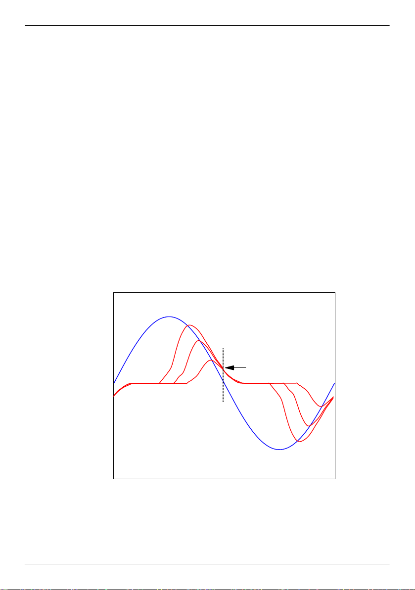
Vmains
Imotor
t
0
1
2
3
At first order, we will neglect the inductive term j.L.ω. This yields: i(t) = k.Ω + r.
The universal motor behaves as a speed-dependent resistor of value k.Ω + r.
As Ω and r do not change very quickly, and v is known, measuring i at a specific time
within the mains period (example: at time t0 in
speed: Ω = (V0 / k. i(t0)) sinωt0 - r / k.
Therefore if we want to keep the speed at a fixed value Ω0, we need to keep i(t0) at
a corresponding fixed value i0:
i0 = V0 .sinωt0 / (k.Ω0 + r )
In practice, each mains period, the micro-controller measures the current at time t0
with its internal analog to digital converter. Then, the current error i(t0)-i0 is calcu
lated, and the micro executes the speed regulation algorithm, which results in a new
firing delay td. This delay is used to fire the triac on the next mains period. It is
counted by the micro controller internal timer. The delay is measured starting from the
mains voltage zero-crossing.
Figure 2) gives an image of the motor
-
Figure 3. Measured Current in a Real Motor (resistive and inductive): Constant
Speed, Variable Load (1: lowest load, 3: highest load)
If we now consider the real universal motor, including the inductive term j.L.ω, we
can apply the same method.
motor. On this figure, while the load is modified, the speed is kept constant by modi-
Figure 3 shows the current and mains voltage for a real
5/22
Page 6

IMPROVED SENSORLESS CONTROL WITH THE ST62 MCU FOR UNIVERSAL MOTOR
fying the triac firing delay. Moving from Figure 2 to Figure 3, we can see two effects
of the inductive term. First effect: at triac turn-on, the motor current does not exhibit a
discontinuity, but changes gradually from 0 to a finite value. Second effect: at mains
voltage zero crossing, the motor current does not reach zero immediately, but keeps
trailing for a few milliseconds. This trailing gives us more freedom to chose the meas
urement time t0. We can even chose the zero crossing instant, which is the easiest
time for the micro-controller (no need to measure time t0 with the timer, we can use
the mains zero-crossing as an interrupt to the micro, which is necessary anyway for
other matters). This is illustrated in
Figure 3, where the arrow shows that the current
is constant at the zero-crossing time while the motor load changes, provided that the
speed is kept constant by adjustment of the firing delay td. For a detailed mathemat
ical discussion, see annex 1.
To summarize, if we want to regulate the speed at a pre-defined set speed, for example 1000 rpm, we must measure the instantaneous motor current on every mains
period at the same time t0 (for example, on every mains voltage zero crossing fol
lowing the positive half-cycle), and maintain this measured current at a fixed set current, 1 ampere for example. For a different set speed, 2000 rpm, we need to regulate
the current around a different value, 0.5 ampere for example (note that a lower cur
rent corresponds to a higher speed).
The regulation is performed by adjustment of the triac firing delay td.
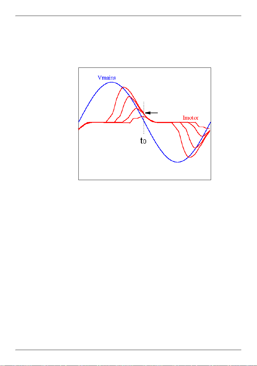
The above described method gives very good results at medium and high speeds.
At very low speeds, we have a second order effect coming into the picture: Figure 4
is identical to Figure 3, except for the presence of a fourth current curve, corresponding to a very large firing delay td (this corresponds to a very low speed, combined with a low load). We can see on this fourth curve that the current at time t0 is
smaller than i0, current of the other 3 curves at this time. This effect is described in
detail in annex 1. We have two solutions to cope with it. The simplest one is to limit
the maximum firing delay (below values in the range of 7 mS, depending on the motor
type). This means limiting the minimum speed which can be regulated. If the applica
tion cannot tolerate this reduction in its speed dynamic range, a second and more
complex solution is to compensate this current measurement distortion, by means of
look-up tables memorized in the micro-controller memory. When the current i(t0) is
measured, if td is larger than a limit value (7 mS for example), i(t0) is increased by a
compensation value extracted from a memory table before it is used to calculate the
current error. This value is a function of the triac firing delay td, and is determined ex
perimentally by characterizing the motor. The regulation system is not very sensitive
to this value, so it is enough to characterize one motor of a given type, it is not neces
-
-
-
-
-
-
-
6/22
Page 7
IMPROVED SENSORLESS CONTROL WITH THE ST62 MCU FOR UNIVERSAL MOTOR
sary to characterize each individual motor. Annex 2 describes how to determine this
compensation table.
Figure 4. Measured Current at Constant Speed (for very large firing delays,
current at time t0 is lower than set current)
7/22
Page 8

IMPROVED SENSORLESS CONTROL WITH THE ST62 MCU FOR UNIVERSAL MOTOR
3 IMPLEMENTATION
Figure 5 gives a schematic of the sensorless motor drive. The heart of the system is
the micro-controller, the ST6220, a low cost 8-bit general purpose micro. It is supplied
directly from the mains by the capacitive supply made of components R2/C1/C2/C3
and of the two diodes. This is made possible by its low current consumption, in the
range of 4 mA. This capacitive supply must be dimensioned to supply the micro, the
operational amplifier, and the triac gate during the firing. Resistor R1 is the current
sense resistor, it is only 0.22 ohm in order to keep the losses as low as possible (in
this example, the motor is a 500 watts type). For this reason, an operational amplifier
is needed in order to provide the micro-controller analog-to-digital converter input (pin
PB1) with a large enough voltage. As this analog-to-digital converter (ADC) is an 8 bit
type, its resolution (minimum voltage step discernible at its input) is around 20 mV
when the micro is supplied from 5 volts. The larger the voltage on the ADC input,
which is the op-amp output after some noise filtering by R6 and C5, the better the res
olution on measured current i(t0), which will be used latter in the speed regulation algorithm. A value around 1 volt is a reasonable compromise. The op-amp must be a
rail-to-rail type, at the output and inputs as well: for the input, the voltage measured
on the sense resistor is very low, and referred to the positive supply VDD. The output
should be able to swing from the micro-controller ground level to its VDD level, which
are the same as for the op-amp itself, in order to make full usage of the ADC dynamic
range.
Two noise filters (R10/C4 and R6/C5) are provided to remove brush noise from the
motor current signal, before it is measured by the internal ADC. Depending on the
motor, and with careful design, it is possible to do with only one filter.
Resistors R3, R4 and capacitor C6 are used to shape the mains voltage before
sending it to the micro input pin PB0. This digital signal, which shows an edge at each
zero-crossing of the mains (positive or negative edge depending on the half-cycle
sign), interrupts the micro-controller program to signal the zero-crossing. It is used to
synchronize the triac firing with the mains, and to trigger the ADC reading in order to
acquire the current value i(t0).
-
8/22
Page 9

IMPROVED SENSORLESS CONTROL WITH THE ST62 MCU FOR UNIVERSAL MOTOR
BTB 08 600 CW
470 uF
10v
5.6V
8 MHz
2x33pF
VDD
TIMER
OSCIN
OSCOUT
NMI
TEST
NRESET
PB7
PB6
PB5
VSS
PA0
PA1
PA2
PA3
PB0
PB1
PB2
PB3
PB4
ST6220
HWD
VDD
RS232
390
0.5W
0.1uF
FUSE
220 V
zero cross.
0.22u
1 k
22 k
750
2.2 k
TS912AI
6
5
8
4
7
2.7 k
68 n
22 k
220k
1N4148
470 nF
400V
MOTOR
0.22 / 3 W
47k
1nF
R1
R2
R3
R4
R5
R6
R7
R8
R9
R10
R11
C1
C2
C3
C4
C5
C6
100
VDD
Figure 5. A low cost 8-bit micro-controller ST6220, a rail-to-rail operational
amplifier TS912, a triac and a small value sense resistor make the
heart of this sensorless speed regulated drive
The triac is controlled by pins PA0/PA1/PA2 of the micro. They are in parallel in order
to get enough current to trigger the triac. The 100 ohm resistor R11 limits the current
in the triac gate.
Two push-buttons are provided on pins PB5 and PB6 of the micro for the user interface. Pushing one speeds up the motor, pushing the other slows it down. Alternatively, it is possible to replace this push-button interface by a potentiometer R8, which
could be measured by the internal ADC. Both are shown on
Figure 5, buttons and po-
tentiometer, but the attached software only implements the push-buttons.
Finally, Figure 5 shows an output of the micro-controller labeled RS232 (together with
the VDD supply). In the attached software, some routines are provided to help in the
application development and motor characterization. They allow to connect the motor
control board to the serial port COM1 of a personal computer. While the motor is run
ning, the personal computer displays in a graphical form motor data such as measured current and firing delay, allowing easy interpretation and measurement. Of
course, it is necessary to use opto-isolated components to connect the computer to
the motor drive. This connection to a personal computer is described in annex 3.
-
9/22
Page 10

IMPROVED SENSORLESS CONTROL WITH THE ST62 MCU FOR UNIVERSAL MOTOR
4 SOFTWARE DESCRIPTION
Figure 6 illustrates the micro-controller program operation. The program consists of a
loop synchronized on the mains zero-crossing (z.c.). Each zero-crossing causes an
interrupt on pin PB0 of the micro. In case of a positive half-cycle, the motor current
i(t0) is measured and saved into variable it0 for latter use. Then, in both cases (positive and negative half-cycle), the micro uses the timer to wait an amount of time td x
48 μS, after which it fires the triac with pins PA0,PA1,PA2 (48 μS is the chosen timer
step). Three pins are used in order to supply up to 3 x 20mA to the triac gate. The
timer is used again to keep the gate activated during 400 μS (TGATE x 48 μS). After
the end of the triac gate activation, two tasks remain to accomplish: in the positive
half-cycle, the micro reads the push-buttons (or potentiometer) to check the user
speed demand; in the negative half-cycle, the regulation algorithm is executed, re
sulting in the calculation of a new value for td, to be applied on next mains cycle.
When this is done, the micro returns to wait mode until the next zero-crossing inter
rupt happens.
•Regulation algorithm: proportional-integral regulation
This algorithm is contained within the subroutines “regul” and “pi”. Its input is the variable it0 (current measured at zero-crossing), and its output the triac firing delay td
(each unit corresponds to 48 μS delay). The variable it0 is first increased by a com
pensation value extracted from a memory table before it is used to calculate the current error. This value is a function of the triac firing delay td. The current error, i_err,
is then obtained by subtracting the current demand icalc0, which depends only upon
the user speed demand. The micro then calculates the proportional and integral
terms of the proportional-integral algorithm: they are simply the current error i_err
multiplied by constants (KP and KI). In the attached example, KP = 1/4 and KI = 1/32,
but these coefficients must be adjusted for a given motor type. They dictate the tran
sient behavior of the regulation. As there is no multiplication instruction in ST6 micro
controllers, it is chosen to multiply or divide only by powers of two (1/4, 1/32, 1/8...) as
this is fast and easy to perform by software. Subroutines for multiplication by 1/4,
1/8, 1/16, 1/32, 1/64 are given in the program. In practice, this restriction is not a
problem, as the transient performance is not very sensitive to these coefficients.
-
-
-
-
10/22
Page 11

IMPROVED SENSORLESS CONTROL WITH THE ST62 MCU FOR UNIVERSAL MOTOR
If we note with index (n) the variables related to the nth mains cycle, the complete PI
(proportional-integral) algorithm can be expressed by:
i_err(n) = it0(n-1) + table(td(n-1)) - icalc0
sum(n) = sum(n-1) + KI * i_err(n)
td(n) = VITMIN - [ sum(n) + KP * i_err(n) ]
table(td(n-1)) is the current compensation coefficient extracted from the table, and associated to the corresponding value of the firing delay td, td(n-1).
sum(n) is the integral term, and KP * i_err(n) the proportional term. VITMIN is a constant equal to the maximum firing delay (150 x 48 μS = 7.2 mS in the example).
This is expressed in the program by:
i_err <- it0 + table(td) - icalc0
sum <- sum_old + KI * i_err
temp1 <- sum + KP * i_err
td <- VITMIN - temp1
sum_old <- sum
11/22
Page 12

IMPROVED SENSORLESS CONTROL WITH THE ST62 MCU FOR UNIVERSAL MOTOR
Figure 6. The program is a loop synchronized on the mains zero crossing (z.c.).
It is identical on both half-cycles, except for the i(t0) current
measurement, regulation subroutine and speed demand subroutine
The adaptation of the program to a specific motor type can be done by adjusting the
coefficients KI and KP, and the contents of compensation table table(td). The table is
necessary only for the largest firing delays (slow speed). The slower the motor should
be able to run, the more attention should be given to the elaboration of this table.
The proportional coefficient KP adjusts how strongly the system reacts to a speed
error: the larger this coefficient, the faster the reaction to load change, but if this term
becomes too large, some instability may occur. The integral coefficient KI adjusts the
transient settling time when the load changes: the larger KI, the faster the settling
time, but again, instability may occur if this coefficient becomes too large. Trial and
error is the best way to find the best compromises.
The latest detail which must be mentioned in the program is the operational amplifier
gain adjust. At high speed, current it0 becomes very small; if we want to measure it
with a reasonable accuracy, we must amplify it even more than in case of low speed.
This is why the op-amp is fitted with a dual gain scheme, with help of resistor R5, con
nected to VDD or left open by the micro pins PB2/PB3/PB4. The op-amp gain is set
to 10 for the low speed range, 40 for the high speed range. This gain setting is man
aged in subroutine “speed”, which also checks for user speed demand.
-
-
12/22
Page 13

IMPROVED SENSORLESS CONTROL WITH THE ST62 MCU FOR UNIVERSAL MOTOR
5 REGULATION PERFORMANCE
Figures 7, 8, 9 show the regulation performance at three speeds typical of a drill. The
horizontal axis shows the motor rms current, which is proportional to the load. The
first two figures show reasonable performance: speed is kept constant within +- 10%.
The last figure, corresponding to a very low speed of 400 rpm, shows a speed increase when the load increases. This can be improved somewhat by fine tuning the
compensation table. Creating a different table for each set speed would also improve
the performance for a given set speed (for example, one table for set speeds 400-600
rpm, one for 600-900 rpm, one for 900-1300 rpm, etc... the example program pro
vides only one table for the whole speed range). However, it should be noted that the
difficulty to find the best compromises increases considerably when we want to regu
late the motor at slower and slower speeds. This is easy to understand conceptually,
as the quantity that we actually measure and regulate is k.Ω + r. When we move to
wards slower speeds, the relative importance of the term k.Ω compared to the resistive term r becomes smaller and smaller. Also, at very low speeds, friction becomes
predominant. This limits the usefulness of the system to moderate speed range appli
cations.
6 CONCLUSION
This document showed how to regulate the universal motor speed without speed
sensor, with the help of a low cost micro controller. The price to pay is some accuracy
loss in the speed regulation, in the order of 10%. In most home appliance applications, such speed variation with varying load is fully acceptable. When the micro investment has been made, it is a good idea to make use of its inherent benefits, flexibility, ease of customization, fast time to market. In a washing machine for example,
the micro can also be used to generate the speed ramps and washing / rinsing se
quences, and control the unbalance; in a drill, it can be used to control or limit the
torque. In the long term, the universal motor should be replaced more and more by
brushless "electronic" motors, such as the DC permanent magnet brushless, or the
switched reluctance motor, due to their higher efficiency and dynamic performances.
However, cost reductions such as the one described in this document should allow
the universal motor to compete successfully for many years in the most cost sensitive
applications.
-
-
-
-
-
13/22
Page 14

IMPROVED SENSORLESS CONTROL WITH THE ST62 MCU FOR UNIVERSAL MOTOR
01234
0
500
1 000
1 500
2 000
speed (rpm)
rms mo to r cu rren t (A )
without
regulation
with regulation
0123456
0
100
200
300
400
500
600
700
speed (rpm)
rms motor current (A)
without
regulation
with
regulation
012345
0
200
400
600
800
1 000
1 200
speed (rpm)
rms motor cu rren t (A )
without
regulation
with regulation
Figures 7, 8, 9. Speed regulation performance (with and without regulation) for
set speeds of 1700, 950 and 400 rpm on a 500W drill. Speeds
are measured after reduction, on the tool shaft
14/22
Page 15

IMPROVED SENSORLESS CONTROL WITH THE ST62 MCU FOR UNIVERSAL MOTOR
7 REFERENCES
[1] Power control with triacs and ST6210 MCU
AN392 - P. Rabier and L. Perier (SGS-THOMSON Microelectronics)
[2] Digital control for brush DC motor
T. Castagnet and J. Nicolai (SGS-THOMSON Microelectronics)
PCIM Nuremberg, June 93
[3] Sensorless motor drive with the ST62 MCU + TRIAC
AN416 - T. Castagnet (SGS-THOMSON Microelectronics)
8 ANNEX
ANNEX 1 MOTOR CURRENT CALCULATION
The motor voltage equation is: v(t) = (k.Ω + r) i(t) + L di/dt
v(t) = 0 while the triac is off (before turn on at time td, and after the turn off caused
by the motor current reaching 0)
v(t) = V0 .sinωt while the triac is on
The solution to the differential equation is:
i(t) = 0 while the triac is off
While the triac is on:
If we neglect the inductance L: i(t) = V0 sinωt / (k.Ω + r)
If we do not neglect the inductance:
i(t) = - exp(-A(t-td)/L) [ B sin ωtd + C cos ωtd] + B sin ωt + C cos ωt
with: A = k.Ω + r
B = AV0 / (A ² + L² ω²)
C = - L ω V0 / (A ² + L² ω²)
td = triac firing delay measured from mains zero-crossing
Figure 10 is a plot of i(t0) versus td at constant speed. Modifying the speed parameter
generates a family of curves. In Figure 11, t0 equals 10 mS: the current i(t0) is measured at the mains voltage zero crossing.
Figure 11 is a plot of i(t) versus t at constant speed. Modifying the parameter td (triac
firing delay) generates a family of curves
15/22
Page 16

IMPROVED SENSORLESS CONTROL WITH THE ST62 MCU FOR UNIVERSAL MOTOR
Figure 10. calculated current versus time at constant speed for various triac
firing delays (resistive and inductive model). Current at t0 is
constant, except at the largest firing delay td of 9 mS.
Figure 11. calculated current at mains zero crossing versus firing delay for
various speeds. For speeds larger than 600 rpm and firing delays
smaller than 7 mS, this current depends only upon speed.
16/22
Page 17

IMPROVED SENSORLESS CONTROL WITH THE ST62 MCU FOR UNIVERSAL MOTOR
ANNEX 2 CREATING THE CURRENT COMPENSATION TABLE
A second assembly program is provided, namedcaract.asm. It must be used in place
of “regul.asm”. Its purpose is to allow characterization of the motor in order to create
the table. Contrary to “regul.asm”, it does not perform any regulation, but instead fires
the triac at a constant delay td which can be adjusted through the whole range
(VITMAX to VITMIN) by means of the two push buttons. At the same time, the RS232
connection allows to measure the present values for td (firing delay) and it0 (meas
ured current at zero crossing), as explained in annex 3. The procedure to follow is described below:
– select the desired speed for which the table must be optimized. Figure 12 gives an
example (600 rpm) of the shape that current it0 has while td is varied. This curve is
in fact one of the curves family in
Figure 12 of annex 1. This speed is obtained with
no load by adjusting td with the push-buttons. The RS232 connection allows to
measure and record td and it0 when the desired speed is obtained.
– add a small constant load on the motor shaft. The speed naturally decreases. Then
decrease the firing delay td with the push buttons until the speed is back to 600 rpm.
At this time, record td and it0.
– increase slightly the load. Decrease td to come back to 600 rpm. Record again td
and it0. Keep increasing the load until td reaches the minimum allowed, and record
a few couples (td,it0).
– If you make a graph of the couples (td,it0) with td in abscissa, you will obtain a curve
similar to the one in
Figure 12. Subtracting the current value for small td, approximately 80 in Figure 12, will give the values for the look-up table: the table coefficients are zero for td = 0 to 4mS, then increase regularly up to approximately 22 for
td = 8mS. (note that, for the vertical axis, the values given are not amperes, but reg
ister values output by the ADC converter. They can be related to the actual current
by taking account that the ADC value changes by one unit for 20 mV voltage change
at its input PB1: when the input is maximum, 5 volts, the ADC value is 255). In the
example of
Figure 12, the table will look similar to the following:
td (mS) 0 1 2 3 4 5 5.5 6 6.5 7 7.5 8
coefficient 0 0 0 0 0 3 4 7 10 15 18 22
-
-
17/22
Page 18

IMPROVED SENSORLESS CONTROL WITH THE ST62 MCU FOR UNIVERSAL MOTOR
Figure 12. Variation of the current at zero-crossing it0 versus firing delay td at
600 rpm, while the load is varying. The cross-hatched area is not
allowed, as friction keeps the motor stalled for very large firing
delays. The set of vertical lines is a graphic representation of the
table contents.
18/22
Page 19

IMPROVED SENSORLESS CONTROL WITH THE ST62 MCU FOR UNIVERSAL MOTOR
ANNEX 3 MONITORING ON A PC COMPUTER SCREEN
In order to monitor various variables during the motor characterization, an RS232
connection is provided in the micro-controller software between the ST6 and a per
sonal computer. In the program “regul.asm”, two data bytes are sent to the PC every
mains cycle: on negative half-cycles, the measured current it0 is sent, and on positive
half-cycles, the calculated firing delay td is sent. The instructions used to send this
data are the following:
for the it0 byte:
ld a,it0
call rs232
and for the td byte:
ld a,td
call rs232
When it is called, the rs232 subroutine sends at 19200 bauds on port pin PA3 the
data byte contained in the accumulator. This takes approximately 0.5 mS. Replacing
it0 or td by another register or RAM variable allows to send any intermediate calculation result or variable (coefficient from look-up table, proportional term, integral term,
current error...). To connect the PA3 and VDD micro-controller pins to the PC require
a level amplification (to boost the signal level from 0-5 volts to -5 / +5 volts) performed
by a Maxim MAX232 circuit, and galvanic isolation, performed by an optocoupler (see
Figure 13). The 9-pin connector must be connected to the COM1 serial port of the
PC.
On the PC side, two executable programs are provided: NUMBER.EXE and
VISU.EXE.
NUMBER.EXE, executed on the PC while the motor is running, displays on the
screen two rows of data in decimal format representing the evolution in time of the re
ceived data it0 and td. The two rows scroll down the screen, and at the same time are
stored in a text file named NUMBER.PRN. Hitting any key stops the program execu
tion. The data file NUMBER.PRN remains, available for latter use. It can be imported
into a spreadsheet program for example, to visualize the curves representing in time
domain the evolution of it0 and td.
Program VISU.EXE, on the other hand, allow to display graphically in real time the
time domain evolution of it0 and td. The attached file EGAVGA.BGI must be present
in the same directory, and the PC must have a VGA (or better) screen, as the graphic
is displayed in 640x480 pixels resolution. Hitting any key (except “e”) stops tempo
rarily the curves drawing, so the user can pause to examine a detail of the display.
-
-
-
-
19/22
Page 20

IMPROVED SENSORLESS CONTROL WITH THE ST62 MCU FOR UNIVERSAL MOTOR
Hitting afterwards any key (except “e”) will resume normal operation. Hitting key “m”
twice stores the data presently displayed on the screen in a text file named
VISU.PRN under the same format as NUMBER.PRN, for latter use. Hitting key “e”
terminates the program execution.
Figure 14 is an example of a file VISU.PRN imported into a spreadsheet program. This is also what is displayed on the PC screen in
real time while the motor is running, and the program VISU.EXE is executing.
Figure 13. Connection motor control board - Personal computer by RS232 serial link.
The DB9 connector must be connected to the COM 1 serial port of the
computer.
Figure 14. Measured data as displayed on the PC screen. The horizontal axis represents
640 points, taken every 20 mS, for a total of 12.8 seconds. The curves show
the regulation response to a load step.
20/22
Page 21

IMPROVED SENSORLESS CONTROL WITH THE ST62 MCU FOR UNIVERSAL MOTOR
9 REVISION HISTORY
Table 1. Revision history
Date Revision Description of changes
October 1996 1 Initial release
12-June-2008 2 Logo modified
21/22
Page 22

IMPROVED SENSORLESS CONTROL WITH THE ST62 MCU FOR UNIVERSAL MOTOR
Please Read Carefully:
Information in this document is provided solely in connection with ST products. STMicroelectronics NV and its
subsidiaries (“ST”) reserve the right to make changes, corrections, modifications or improvements, to this
document, and the products and services described herein at any time, without notice.
All ST products are sold pursuant to ST’s terms and conditions of sale.
Purchasers are solely responsible for the choice, selection and use of the ST products and services described
herein, and ST assumes no liability whatsoever relating to the choice, selection or use of the ST products and
services described herein.
No license, express or implied, by estoppel or otherwise, to any intellectual property rights is granted under
this document. If any part of this document refers to any third party products or services it shall not be deemed
a license grant by ST for the use of such third party products or services, or any intellectual property contained
therein or considered as a warranty covering the use in any manner whatsoever of such third party products
or services or any intellectual property contained therein.
UNLESS OTHERWISE SET FORTH IN ST’S TERMS AND CONDITIONS OF SALE ST DISCLAIMS ANY
EXPRESS OR IMPLIED WARRANTY WITH RESPECT TO THE USE AND/OR SALE OF ST PRODUCTS
INCLUDING WITHOUT LIMITATION IMPLIED WARRANTIES OF MERCHANTABILITY, FITNESS FOR A
PARTICULAR PURPOSE (AND THEIR EQUIVALENTS UNDER THE LAWS OF ANY JURISDICTION), OR
INFRINGEMENT OF ANY PATENT, COPYRIGHT OR OTHER INTELLECTUAL PROPERTY RIGHT.
UNLESS EXPRESSLY APPROVED IN WRITING BY AN AUTHORIZED ST REPRESENTATIVE, ST
PRODUCTS ARE NOT RECOMMENDED, AUTHORIZED OR WARRANTED FOR USE IN MILITARY, AIR
CRAFT, SPACE, LIFE SAVING, OR LIFE SUSTAINING APPLICATIONS, NOR IN PRODUCTS OR
SYSTEMS WHERE FAILURE OR MALFUNCTION MAY RESULT IN PERSONAL INJURY, DEATH, OR
SEVERE PROPERTY OR ENVIRONMENTAL DAMAGE. ST PRODUCTS WHICH ARE NOT SPECIFIED
AS "AUTOMOTIVE GRADE" MAY ONLY BE USED IN AUTOMOTIVE APPLICATIONS AT USER’S OWN
RISK.
Resale of ST products with provisions different from the statements and/or technical features set forth in this
document shall immediately void any warranty granted by ST for the ST product or service described herein
and shall not create or extend in any manner whatsoever, any liability of ST.
ST and the ST logo are trademarks or registered trademarks of ST in various countries.
Information in this document supersedes and replaces all information previously supplied.
The ST logo is a registered trademark of STMicroelectronics. All other names are the property of their
© 2008 STMicroelectronics - All rights reserved
respective owners.
22/22
STMicroelectronics group of companies
Australia - Belgium - Brazil - Canada - China - Czech Republic - Finland - France - Germany - Hong Kong -
India - Israel - Italy - Japan - Malaysia - Malta - Morocco - Singapore - Spain - Sweden - Switzerland - United
Kingdom - United States of America
www.st.com
 Loading...