


AN842
APPLICATION NOTE
7-segment display drive
using the ST6-REALIZER
INTRODUCTION
Seven segment devices are often preferred in display applications where high luminescence is required,
both for indoor and outdoor applications.
Controlling the display is normally but one of many tasks handled by a typical application. The techniques
described in this note are of a general nature and may be applied to a variety of applications.
Hardware considerations are reviewed and generation of control software using the ST6-REALIZER is
described.
June 2008 Rev 2 1/8
7-segment display drive using the ST6-REALIZER
a
bf
ce
d
g
DP
1 PRINCIPLE OF OPERATION
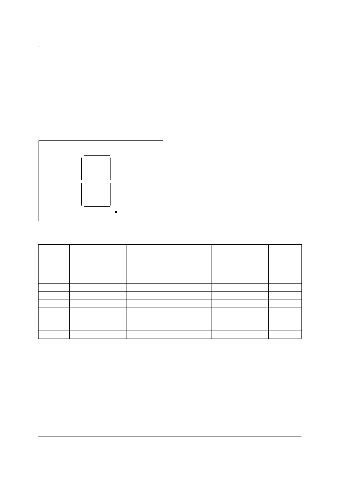
A 7-Segment Display consists of 7 LED's arranged in a figure-eight pattern, such that by selectively powering various combinations of segments alphanumeric characters may be displayed; a further LED is
present which, when powered, causes a dot or decimal point to be displayed (Figure 1). Each LED is
turned on by forward biasing its respective anode, all segment cathodes being commoned (Common Anode devices also exist).
The Digital Point LED is generally used to display numbers containing a non-integer part. Table 1 illustrates the required segment patterns for numeric representation, including the optional Decimal Point
character.
Figure 1. Structure of a 7 segment display
Table 1. LED's turned on for a given digit
abcde f gDP
0 1111110 X
1 0110000 X
2 1101101 X
3 1111001 X
4 0110011 X
5 1011011 X
6 1011111 X
7 1100000 X
8 1111111 X
9 1111011 X
DPXXXXXXX 1
X = Don't care
Biasing can be either continuous or multiplexed as long as the refresh frequency is high enough to ensure
image persistence for the human eye (at least 20 cycles per second to avoid flicker).
2/8
7-segment display drive using the ST6-REALIZER
2 PRACTICAL IMPLEMENTATION
2.1 Hardware layout
Biasing is achieved using the ST62 MCU's I/O lines. One line is used to bias the common cathode, while
7 lines are assigned to LED segments a - g and a further line, if required, to the DP. Each segment of the
display can thus be turned on or off, depending on the value written to the corresponding I/O line.
2.2 Software generation
Control software is automatically generated by the ST6-REALIZER, on the basis of a functional description.
The digit to be displayed is available as a variable, "Digit value". The display control software must then
write the relevant value to the I/O lines in accordance with Table 1.
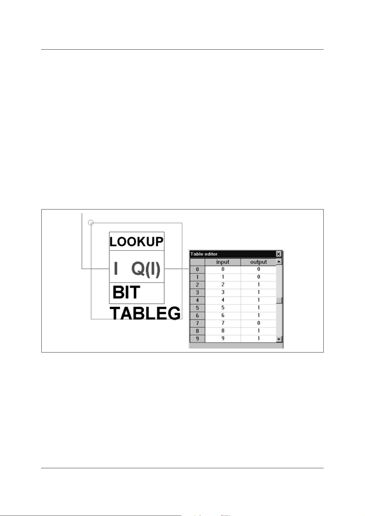
The ST6-REALIZER library provides a component, the lookuptable, for this kind of application. This table
assigns to each variable input value a constant output value defined in the ROM memory of the ST62
MCU. If a lookup table is defined for each LED or segment, the output data is of BIT type as shown in the
Figure 2 for segment g.
Figure 2. Lookup table for segment g
Finally, the resultant bits are transferred to the I/O port via the digout components (Figure 3).
3/8

7-segment display drive using the ST6-REALIZER
Figure 3. 7-segment drive with bitwise lookup table
However this approach implies the use of 7 lookup tables (1 for each segment). This means the MCU has
to scan a table 7 times, with consequent impact on execution time. A better alternative is to concatenate
the 7 segments into a bytewise variable, and therefore use only one lookup table with output data of
UBYTE type. In this case, the content of the lookup table is a byte defined as described in Table 2:
Table 2. 7-segment coding in one byte
D7 D6 D5 D4 D3 D2 D1 D0
Don't care g f e d c b a
The resulting byte is then transferred to 7 digout components by using an unpacker component, bunpack,
and gives the complete description as per Figure 4.
4/8

7-segment display drive using the ST6-REALIZER
Figure 4. 7-segment drive with bytewise lookup table
By using the simulation features of the ST6-REALIZER, the reduction in execution time has been quantified as follows:
7 bitwise lookup tables: 5170µs
1 bytewise lookup table: 1125µs
2.3 Multiple digit display
These concepts can be extended to multiple-digit display systems. The simplest approach is to drive each
digit separately, which requires at least 7 I/O lines per digit (excluding DP and assuming the common
cathodes are tied to an external supply). It is possible to greatly reduce the number of I/O lines by adopting
a multiplexing technique. In this scheme, each of the segments are common for all display digits, while the
cathodes are driven sequentially to select the active digit. The 7 I/O lines which drive the segments are
then driven in accordance with the currently driven cathode. The lookup table is common to all digits but
its input will vary depending on the digit to be displayed.
The input thus depends on the cathode selection signal, which must switch with a period shorter than the
persistence time of the human eye in order to avoid flicker. In the present case, 20ms has been chosen.
Figure 5 illustrates such an application, where two digits are used to display values ranging from 0 to 99.
5/8

7-segment display drive using the ST6-REALIZER
Figure 5. Multiple digit display application
6/8

3 REVISION HISTORY
Table 3. Revision history
Date Revision Description of changes
November 1995 1 Initial release
13-June-2008 2 Logo modified
7-segment display drive using the ST6-REALIZER
7/8

7-segment display drive using the ST6-REALIZER
Please Read Carefully:
Information in this document is provided solely in connection with ST products. STMicroelectronics NV and its
subsidiaries (“ST”) reserve the right to make changes, corrections, modifications or improvements, to this document, and
the products and services described herein at any time, without notice.
All ST products are sold pursuant to ST’s terms and conditions of sale.
Purchasers are solely responsible for the choice, selection and use of the ST products and services described herein,
and ST assumes no liability whatsoever relating to the choice, selection or use of the ST products and services described
herein.
No license, express or implied, by estoppel or otherwise, to any intellectual property rights is granted under this document.
If any part of this document refers to any third party products or services it shall not be deemed a license grant by ST for
the use of such third party products or services, or any intellectual property contained therein or considered as a warranty
covering the use in any manner whatsoever of such third party products or services or any intellectual property contained
therein.
UNLESS OTHERWISE SET FORTH IN ST’S TERMS AND CONDITIONS OF SALE ST DISCLAIMS ANY EXPRESS
OR IMPLIED WARRANTY WITH RESPECT TO THE USE AND/OR SALE OF ST PRODUCTS INCLUDING WITHOUT
LIMITATION IMPLIED WARRANTIES OF MERCHANTABILITY, FITNESS FOR A PARTICULAR PURPOSE (AND
THEIR EQUIVALENTS UNDER THE LAWS OF ANY JURISDICTION), OR INFRINGEMENT OF ANY PATENT,
COPYRIGHT OR OTHER INTELLECTUAL PROPERTY RIGHT.
UNLESS EXPRESSLY APPROVED IN WRITING BY AN AUTHORIZED ST REPRESENTATIVE, ST PRODUCTS ARE
NOT RECOMMENDED, AUTHORIZED OR WARRANTED FOR USE IN MILITARY, AIR CRAFT, SPACE, LIFE
SAVING, OR LIFE SUSTAINING APPLICATIONS, NOR IN PRODUCTS OR SYSTEMS WHERE FAILURE OR
MALFUNCTION MAY RESULT IN PERSONAL INJURY, DEATH, OR SEVERE PROPERTY OR ENVIRONMENTAL
DAMAGE. ST PRODUCTS WHICH ARE NOT SPECIFIED AS "AUTOMOTIVE GRADE" MAY ONLY BE USED IN
AUTOMOTIVE APPLICATIONS AT USER’S OWN RISK.
Resale of ST products with provisions different from the statements and/or technical features set forth in this document
shall immediately void any warranty granted by ST for the ST product or service described herein and shall not create or
extend in any manner whatsoever, any liability of ST.
ST and the ST logo are trademarks or registered trademarks of ST in various countries.
Information in this document supersedes and replaces all information previously supplied.
The ST logo is a registered trademark of STMicroelectronics. All other names are the property of their respective owners.
© 2008 STMicroelectronics - All rights reserved
STMicroelectronics group of companies
Australia - Belgium - Brazil - Canada - China - Czech Republic - Finland - France - Germany - Hong Kong - India - Israel
- Italy - Japan - Malaysia - Malta - Morocco - Singapore - Spain - Sweden - Switzerland - United Kingdom - United States
of America
www.st.com
8/8
 Loading...