

Page 1

AN841
APPLICATION NOTE
A clock design using the ST6-REALIZER
INTRODUCTION
Today Clock systems are used in more and more applications because of the added features they open:
Current Time display, Event dating, process start time programming,...
Generally, this feature is part of a more global system, and cost effective solutions are required.
MCU solutions are more and more often used thanks to the onboard provided Timer and all the possibili-
ties offered by the MCU embedded resources to manage other tasks. This approach allows single chip solutions which brings a great advantage in fields like small home appliances.
A simple time of day clock, provided with an alarm feature, has then been developed as example with the
help of the ST6-REALIZER.
June 2008 Rev 2 1/10
Page 2

A clock design using the ST6-REALIZER
1 APPLICATION OVERVIEW
The clock system provides the following features:
– Current time counting
– Alarm triggering at a defined time
– Current time setup
– Alarm time setup
The time values are represented in the HH:MM format, but the described concept can easily be extended
to representation in seconds. By using this HH:MM format, the time value is represented by a pair of inte
ger variables ranging in [0..59] for the minutes and [0..23] for the hours.
The user interface consists of 4 keys:TIME SETUP, ALARM SETUP, HOURS and MINUTES.
With these 4 keys, both the current time and the alarm time can be adjusted:
– When the key TIME SETUP is activated, the Hours (Resp. Minutes) variable of the current time is in-
creased at each activation of the key HOURS (Resp. MINUTES).
– When the key ALARM SETUP is activated, the Hours (Resp. Minutes) variable of the Alarm time is in-
creased at each activation of the key HOURS (Resp. MINUTES).
A decrementation of any of the time variables is achieved by successive incrementations since they are
reset when they reach the maximum value (23 for the hours and 59 for the minutes). For instance, passing
from 22 Hours to 2 Hours needs 4 steps: 22 > 23 > 0 > 1 > 2.
-
2/10
Page 3
A clock design using the ST6-REALIZER
Current
Time
Computing
VR02064A
Alarm
Time
Setup
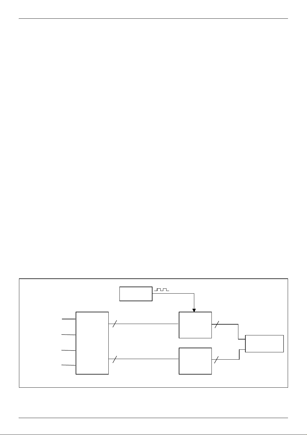
COMPARISON
TIMEBASE
USER
INTERFACE
TIME SETUP
ALARM SETUP
HOURS
MINUTES
Hour, Min Setup
Hour, Min Alarm Setup
2
2
2
2
2 FUNCTIONAL PRINCIPLE
All the featured functions of the clock system are managed on the final application under software control
by the MCU. However, using the ST6-REALIZER allows to generate this application software by function
al description of the system. Thus the software development can be achieved by a system oriented or
hardware like description.
2.1 Current time counting
The system uses a 1 Hz timebase generated with the embedded Timer of the ST62 MCU. This oscillating
timebase is used to trigger three chained Modulo-N counters (Unit Counter):
– one for the seconds (n = 60)
– one for the minutes (n = 60)
– one for the hours (n = 24).
When any of these Unit Counter reaches its maximum value, a clock is issued to increment the Unit coun-
ter of the next stage.
2.2 Current time setup
The current time value is modified by incrementation of the counters used for the current time counting.
This is achieved by duplicating the clock input of the involved counter directly in the current time counting
block. Practically, two different additional clocks are needed, one for the minutes incrementation and one
for the hours incrementation. Each of these additional clocks is controlled by the combination of the keys,
TIME SETUP, HOURS and MINUTES.
-
2.3 Alarm time setup
A structure very close to the current time setup has been used. Two counters are used, one for the minutes, and one for the hours. Unlike current time counting, the content of these counters can be modified
only by pressure on the keys ALARM SETUP, HOURS and MINUTES.
2.4 Alarm triggering
An alarm process is launched when the current time is equal to the alarm predefined time. The occurrence
is enabled by a double comparison: Hours equal, Minutes equal.
Figure 1. Application block diagram
3/10
Page 4

A clock design using the ST6-REALIZER
VR02064C
CLKin
Value
CLKout
3 PRACTICAL REALISATION
3.1 Timebase
The timebase is described by using the Oscillator component of the ST6-REALIZER library. Any “realtime” value can be defined for the period in a very explicit way. In the present case, the 1Hz timebase is
defined as an oscillating squarewave with half a period (Level High duration) of 00:00:00.50 in the
HH:MM:SS.xx format (
Practically, the ST6-REALIZER uses the embedded Timer of the ST62 MCU as timebase, and generates
by software any periodic variable.
Figure 2. Timebase description
Figure 2).
3.2 Current time counting
Each of the 3 chained Modulo-N counters presents:
– An input clock issued from the previous stage (Timebase for the 1st stage).
– An output clock to activate the following stage.
– A bytewise output with the current counted value (Second, Minute or Hour).
– An optional clock for the incremental set-up process.
Any content change can be performed only during a input clock transition from 0 to 1. Thus the reset
phase when the counter reaches its maximum value has to be anticipated. For instance the Hours Modu
lo-24 counter is reset if the two following conditions occur: Content equal to 23 and input clock transition.
In parallel, the resulting Reset signal is issued as output clock to increment the next stage as shown on the
Figure 3 in the case of a Modulo-5 counter.
Figure 3. Clock synchronism principle
-
4/10
Page 5

A clock design using the ST6-REALIZER
VR02064B
CLKin
A=B=C
Q
Val
N-1
N
Pr
0
Each Modulo N block is based on a Counter component provided within the ST6-REALIZER standard library. This symbol presents the advantage of generating a numeric variable as output. This means that
any numeric or arithmetic operation can be directly performed on that variable without worrying on its bi
nary representation. In the present case, the detection of the maximum value is achieved with a comparator symbol.
The comparator output is injected into the feedback loop at the falling edge of the input clock. This avoids
any parasitic Preset during the High level of the input clock when the comparator output switches to High
level. In parallel, the counter incrementation is prevented by forcing to Low level the Up input of the coun
ter.
Finally, each Unit Counter is represented in the ST6-REALIZER environment as shown in the Figure 4.
Figure 4. Unit Counter description
-
-
Figure 5. Waveforms of the Current Time Counters
5/10
Page 6

A clock design using the ST6-REALIZER
3.3 Current Time setup
The incrementation clock (Up input of the symbol) is duplicated through an OR gate with an external clock,
Setup signal, for Hours or Minutes setup. Any activation on this clock increments of 1 the content of the
counter (
Figure 6. Current Time setup with a duplicated clock
Figure 6).
6/10
Page 7

A clock design using the ST6-REALIZER
3.4 Alarm Time setup
As for the Current Time setup, the Alarm Time setup is achieved by incrementation of two Modulo-N
counters, one for the Minutes and one for the Hours. Each of them has his own input clock controlled by
the combination of the keys ALARM SETUP, HOURS and MINUTES.
A feedback loop is still needed to reset the counter when the maximum value is reached but its implementation can be much more simple than in the Current Time counting blocks. In fact a precise synchronism
is not mandatory, and a basic solution can be used (
Figure 7. Alarm Time setup
Figure 7).
7/10
Page 8

A clock design using the ST6-REALIZER
4 CONCLUSION
With the help of the ST6-REALIZER, the basic modules of a time of day clock have been developed. The
graphical description facility of the tool allows a modular description of the application, and therefore a
progressive development.
8/10
Page 9

5 REVISION HISTORY
Table 1. Revision history
Date Revision Description of changes
October 1995 1 Initial release
13-June-2008 2 Logo modified
A clock design using the ST6-REALIZER
9/10
Page 10

A clock design using the ST6-REALIZER
Please Read Carefully:
Information in this document is provided solely in connection with ST products. STMicroelectronics NV and its
subsidiaries (“ST”) reserve the right to make changes, corrections, modifications or improvements, to this document, and
the products and services described herein at any time, without notice.
All ST products are sold pursuant to ST’s terms and conditions of sale.
Purchasers are solely responsible for the choice, selection and use of the ST products and services described herein,
and ST assumes no liability whatsoever relating to the choice, selection or use of the ST products and services described
herein.
No license, express or implied, by estoppel or otherwise, to any intellectual property rights is granted under this document.
If any part of this document refers to any third party products or services it shall not be deemed a license grant by ST for
the use of such third party products or services, or any intellectual property contained therein or considered as a warranty
covering the use in any manner whatsoever of such third party products or services or any intellectual property contained
therein.
UNLESS OTHERWISE SET FORTH IN ST’S TERMS AND CONDITIONS OF SALE ST DISCLAIMS ANY EXPRESS
OR IMPLIED WARRANTY WITH RESPECT TO THE USE AND/OR SALE OF ST PRODUCTS INCLUDING WITHOUT
LIMITATION IMPLIED WARRANTIES OF MERCHANTABILITY, FITNESS FOR A PARTICULAR PURPOSE (AND
THEIR EQUIVALENTS UNDER THE LAWS OF ANY JURISDICTION), OR INFRINGEMENT OF ANY PATENT,
COPYRIGHT OR OTHER INTELLECTUAL PROPERTY RIGHT.
UNLESS EXPRESSLY APPROVED IN WRITING BY AN AUTHORIZED ST REPRESENTATIVE, ST PRODUCTS ARE
NOT RECOMMENDED, AUTHORIZED OR WARRANTED FOR USE IN MILITARY, AIR CRAFT, SPACE, LIFE
SAVING, OR LIFE SUSTAINING APPLICATIONS, NOR IN PRODUCTS OR SYSTEMS WHERE FAILURE OR
MALFUNCTION MAY RESULT IN PERSONAL INJURY, DEATH, OR SEVERE PROPERTY OR ENVIRONMENTAL
DAMAGE. ST PRODUCTS WHICH ARE NOT SPECIFIED AS "AUTOMOTIVE GRADE" MAY ONLY BE USED IN
AUTOMOTIVE APPLICATIONS AT USER’S OWN RISK.
Resale of ST products with provisions different from the statements and/or technical features set forth in this document
shall immediately void any warranty granted by ST for the ST product or service described herein and shall not create or
extend in any manner whatsoever, any liability of ST.
ST and the ST logo are trademarks or registered trademarks of ST in various countries.
Information in this document supersedes and replaces all information previously supplied.
The ST logo is a registered trademark of STMicroelectronics. All other names are the property of their respective owners.
© 2008 STMicroelectronics - All rights reserved
STMicroelectronics group of companies
Australia - Belgium - Brazil - Canada - China - Czech Republic - Finland - France - Germany - Hong Kong - India - Israel
- Italy - Japan - Malaysia - Malta - Morocco - Singapore - Spain - Sweden - Switzerland - United Kingdom - United States
of America
www.st.com
10/10
 Loading...