

Page 1

AN839
APPLICATION NOTE
Analog multiple key decoding
using the ST6-REALIZER
INTRODUCTION
The ST6 On-chip Analog to Digital Converter (ADC) is a useful peripheral integrated into the silicon of the
ST6 family members. One of its practical applications is to decode a number of keys through only one I/O
port pin. The technique is to connect the keys by a resistive voltage divider to the converter input. This
principle is particularly interesting since it requires only one I/O pin whereas a traditional matrix keyboard
requires a high number of I/O pins.
A practical application has been developed with the ST6-REALIZER environment and is illustrated in this
note.
Hardware considerations for the keyboard design are reviewed while the software generation by the
ST6-REALIZER is described.
June 2008 Rev 2 1/7
Page 2

Analog multiple key decoding using the ST6-REALIZER
1 PRINCIPLE OF OPERATION
The basic circuit of the decoder consists of a pull-up resistor connected to the ADC input, with the first key
directly switching to ground. The following keys are then connected in sequence to the ADC input through
serial resistors. The combination of the pull-up resistor, the serial resistors and the pressed key form a resistive voltage divider (Figure 1).
Figure 1. Analog keyboard resistor key matrix
When a key is pressed, the voltage at the ADC input is given by the activated voltage divider, generating
a different voltage at the ADC input for each key pressed. If the top key is pressed, the voltage measured
is always zero while the default voltage at the ADC input (if no key is pressed) is Vdd.
This analog voltage is converted by the ADC and the digital output value is used to determine which
switch is closed. It can be seen that if more than one key is pressed at the same time, the key detected is
the key in the chain closest to the ADC input. This allows the keys in the keyboard to be prioritised (Figure
2).
Figure 2. Multiple key press
Depending on the identified key, a direct signal activation can be achieved or a selective jump in the program flow can be performed.
2/7
Page 3
Analog multiple key decoding using the ST6-REALIZER
2 PRACTICAL REALISATION
2.1 Keyboard hardware description
The serial resistors are selected in order to give an equal distribution of voltage between Vdd (No key
pressed) and Vss (Last key pressed) for each switch combination, so as to give the best noise margin between keys. For n keys, the resistor values should be selected such that the voltage for the second key
from top is Vdd/n, for the 3rd 2Vdd/n, for the 4th 3Vdd/n and for the nth (n-1)Vdd/n.
Practically the maximum number of keys is limited by the precision of the resistors that gives for each key
pressed a voltage value within a window around the theoretical value.
In the case of a 10 keys system, the values (In Ohm) of the Table 1 for the resistors network have been
chosen.
Taking into account a +/- 2% resistors, voltage values and conversion results of the Table 2 can be obtained. Vmin is obtained when the serial resistors are at their minimum value and the pull-up resistor Rp
is at its maximum value. Vmax is obtained when the serial resistors are at their maximum value while the
pull-up resistor Rp is at its minimum value.
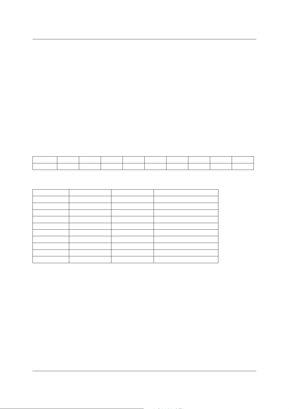
Table 1. Used resistors
Rp R1 R2 R3 R4 R5 R6 R7 R8 R9
10000.00 1100.00 1300.00 1800.00 2400.00 3300.00 5100.00 8200.00 16000.00 51000.00
Table 2. Voltage at the ADC input and 8bit conversion result (5V supply)
Active key Vmin Vmax Conversion result
Key0 0.00 0.00 0-0
Key1 0.48 0.51 24-26
Key2 0.94 1.00 48-51
Key3 1.44 1.52 73-78
Key4 1.94 2.04 99-104
Key5 2.44 2.54 124-129
Key6 2.95 3.05 151-156
Key7 3.45 3.54 179-180
Key8 3.95 4.02 202-205
Key9 4.48 4.52 229-230
The condition no key pressed corresponds to a result of 255.
2.2 Software generation
Thanks to the use of the ST6-REALIZER development tool, the application software is automatically generated from a graphical description of the application.
The functional description of the application includes:
1) The analog input through an ADC to read the value issued by the voltage dividers.
2) Key recognition.
3) Transfer of the result to other functional blocks, or conditional jumps in a state machine.
3/7
Page 4

Analog multiple key decoding using the ST6-REALIZER
The core is the recognition of the pressed key. This is achieved by comparing the digitised analog value
with the range limits defined in the Table 2. However these ranges [0-0], [24-26],...., [229,230] are not con-
tiguous, which implies two comparisons (Upper limit and lower limit) to check that a value is a portion to a
range. It means more ROM and RAM used with an higher execution time. Thus some extended ranges
with common limits have been defined as shown in the Table 3.
Table 3. Recognition ranges
Key pressed Recognition ranges
Key0 0-12
Key1 12-37
Key2 37-62
Key3 62-88
Key4 88-114
Key5 114-140
Key6 140-165
Key7 165-190
Key8 190-217
Key9 217-244
None 244-255
A range limit value is never reached (See Table 2), therefore no ambiguous situation can occur.
The key pressed can then be recognised with numeric comparators and some logical gates as shown in
the Figure 3. The output signals generated Key 0,.., Key 9, None are logical signals and can therefore be
used both as input signals to other functions or as conditions in a state machine.
Figure 3. Key recognition by analog value evaluation
4/7
Page 5

Analog multiple key decoding using the ST6-REALIZER
2.3 Possible improvements
It can be noticed that the inputs A and C of the comparators are interpreted as variables to which have
been assigned fixed values, the range limits. Even though this does not have any importance for the application process itself, it must be taken into account in some cases. In fact, some RAM locations, normally dedicated to variable storage, are used to store these constant values. This reduces the RAM space
available for the surrounding application (Data processing, I/O control,..).
This can be improved by creating a specific comparison symbol where the reference values are defined
as constant. Thus the limit values are stored in the ROM and not in the RAM space.
While doing this, it is also possible to fine tune the symbol function for the application. In the present case,
the new symbol has been defined as follows:
The variable input value is compared to 2 reference values Bot, Top attached to the symbol instance, providing 3 output:
– Input > Top
– Bot <= Input <= Top
– Input < Bot
Eventually, only 5 comparators are used and only one RAM location is used by the digitised representation of the voltage value instead of 11 in the previous case (Input value plus 10 border values).
The symbol customisation feature provided by the ST6-REALIZER environment thus permits then to have
a more simple graphical description (Only 5 comparators) while optimizing the memory requirements
(Figure 4).
Figure 4. System optimization by using customised components
5/7
Page 6

Analog multiple key decoding using the ST6-REALIZER
3 REVISION HISTORY
Table 4. Revision history
Date Revision Description of changes
October 1995 1 Initial release
13-June-2008 2 Logo modified
6/7
Page 7

Analog multiple key decoding using the ST6-REALIZER
Please Read Carefully:
Information in this document is provided solely in connection with ST products. STMicroelectronics NV and its
subsidiaries (“ST”) reserve the right to make changes, corrections, modifications or improvements, to this document, and
the products and services described herein at any time, without notice.
All ST products are sold pursuant to ST’s terms and conditions of sale.
Purchasers are solely responsible for the choice, selection and use of the ST products and services described herein,
and ST assumes no liability whatsoever relating to the choice, selection or use of the ST products and services described
herein.
No license, express or implied, by estoppel or otherwise, to any intellectual property rights is granted under this document.
If any part of this document refers to any third party products or services it shall not be deemed a license grant by ST for
the use of such third party products or services, or any intellectual property contained therein or considered as a warranty
covering the use in any manner whatsoever of such third party products or services or any intellectual property contained
therein.
UNLESS OTHERWISE SET FORTH IN ST’S TERMS AND CONDITIONS OF SALE ST DISCLAIMS ANY EXPRESS
OR IMPLIED WARRANTY WITH RESPECT TO THE USE AND/OR SALE OF ST PRODUCTS INCLUDING WITHOUT
LIMITATION IMPLIED WARRANTIES OF MERCHANTABILITY, FITNESS FOR A PARTICULAR PURPOSE (AND
THEIR EQUIVALENTS UNDER THE LAWS OF ANY JURISDICTION), OR INFRINGEMENT OF ANY PATENT,
COPYRIGHT OR OTHER INTELLECTUAL PROPERTY RIGHT.
UNLESS EXPRESSLY APPROVED IN WRITING BY AN AUTHORIZED ST REPRESENTATIVE, ST PRODUCTS ARE
NOT RECOMMENDED, AUTHORIZED OR WARRANTED FOR USE IN MILITARY, AIR CRAFT, SPACE, LIFE
SAVING, OR LIFE SUSTAINING APPLICATIONS, NOR IN PRODUCTS OR SYSTEMS WHERE FAILURE OR
MALFUNCTION MAY RESULT IN PERSONAL INJURY, DEATH, OR SEVERE PROPERTY OR ENVIRONMENTAL
DAMAGE. ST PRODUCTS WHICH ARE NOT SPECIFIED AS "AUTOMOTIVE GRADE" MAY ONLY BE USED IN
AUTOMOTIVE APPLICATIONS AT USER’S OWN RISK.
Resale of ST products with provisions different from the statements and/or technical features set forth in this document
shall immediately void any warranty granted by ST for the ST product or service described herein and shall not create or
extend in any manner whatsoever, any liability of ST.
ST and the ST logo are trademarks or registered trademarks of ST in various countries.
Information in this document supersedes and replaces all information previously supplied.
The ST logo is a registered trademark of STMicroelectronics. All other names are the property of their respective owners.
© 2008 STMicroelectronics - All rights reserved
STMicroelectronics group of companies
Australia - Belgium - Brazil - Canada - China - Czech Republic - Finland - France - Germany - Hong Kong - India - Israel
- Italy - Japan - Malaysia - Malta - Morocco - Singapore - Spain - Sweden - Switzerland - United Kingdom - United States
of America
www.st.com
7/7
 Loading...