

Page 1
AN832
A
A
APPLICATION NOTE
L4981A SYNCHRONIZATION
by C. Adragna
Devices Description
In most of SMPS using power factor correction, the convertion is accomplished with a PFC stage, in boost topology, that delivers a preregulated DC voltage to a downstream section. This provides the regulated final DC
buses, ensuring also the galvanic insul ation from the mai ns. Both sect ions use a P.W.M. technique eac h with
their own control.
This means that two different switch mode controllers work very close one to the other producing some potential
problem (eg. interferences, beating etc.).
The L4981A controller is provided with an input/output (I/O) synchronization pin (see datasheet pin16 description) which allows the device to be used both as a master or a slave in synchronised configuration.
Let us take into consideration how to interface the L4981A with other PWM controllers each requiring different
interconnections. The devices that have been considered in the following examples are the L4990 (PWM primary contoller provided with I/O sync.) and the UC3842 PWM controller without any dedicated pin for sync.).
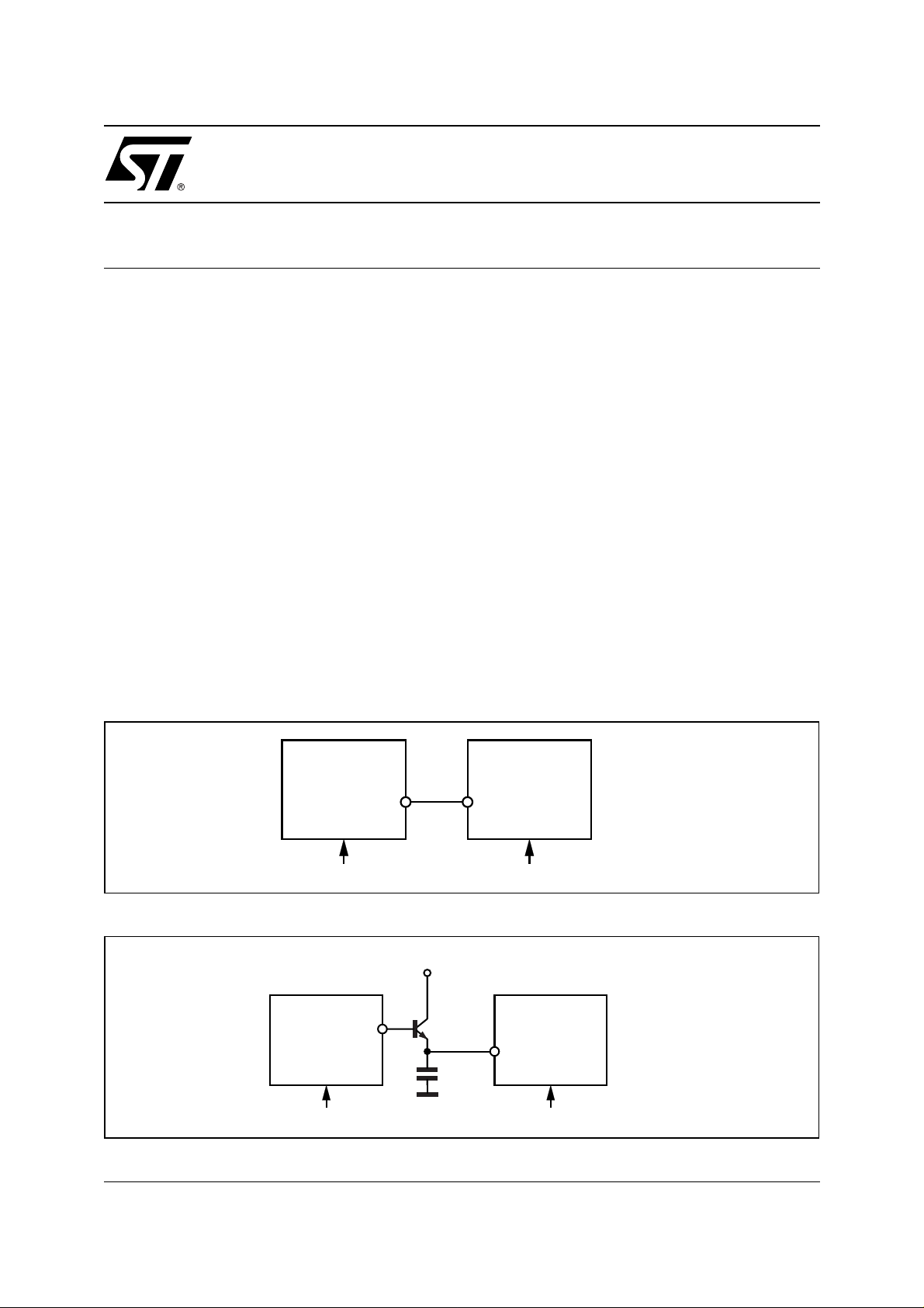
When L4990 with L4981A are used, different situations can be considered :
The PFC controller L4981A is the master and the L4990 is the s l ave (see fig. 1). Since the L4990 is provided
with a positive edge input sync., the two sync. pins can be simply wired together.
The L4990 is the master and the L4981A is the slave (see fig. 2).
Figure 1. Sync. example with L4981A used as master.
L4981A L4990
16 1
MASTER SLAVE
(fsw1)OSC (fsw2)OSCfsw1 > fsw2
Figure 2. Sync. example with L4981A used as slave
Ref
1
47pFMASTER SLAVE
16
L4981AL4990
D95IN293
November 2003
(fsw1)OSC (fsw2)OSCfsw1 > fsw2
D95IN294
1/3
Page 2
AN832 APPLICATION NO TE
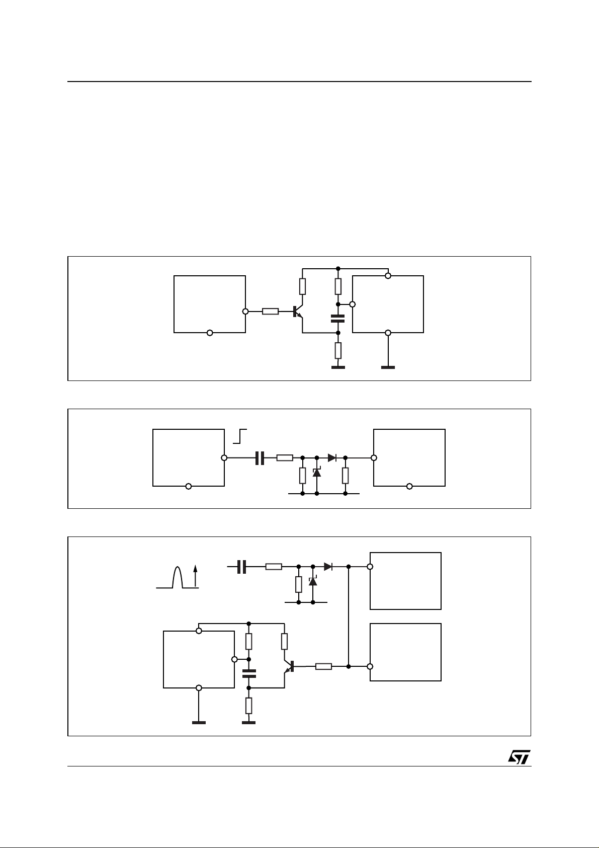
The L4981A needs a m inimum set-up time to recognize the sync. signal (see datasheet) and for this reason the
reported circuit is suggested. Using the UC3842 with the L4981A it is necessary to consider that the UC3842
does not have a dedicated sync. pin.
The suggested circuits are shown in fig. 3 and 4 for both master/slave configurations. For the above described
solut ions , it is n ece ss a ry to ta ke c are of pro pe rly s ett ing the osc illa ti on frequency of the two devices: in practice
the master oscillator frequency has to be higher than the slave one in any condition.
Finally, in fig. 5, it is mentioned an example in which an external frequency synchronizes both the PFC and the
PWM controller (L4990 or UC3842).
This can be a real situation in a TV or monitor application.
Figure 3. Sync. example between L4981A and a curren t mode con trolle r.
Figure 4.
Figure 5.
100 8.2K
8
L4981A
16
MASTER
616
MASTER SLAVE
VP ≈40V
470pF
1K
10nF
47
D95IN295A
120Ω 1N4148
3.3K 6.2V470pF 2.2K
120Ω
3.3K 6.2V
4
UC3842
D95IN296B
1
5
SLAVE
L4981AUC3842
L4990
2/3
8
UC3842
5
1008.2K
4
10nF
47
1K
L4981A
16
D95IN297A
Page 3

AN832 APPLICATION NOTE
Information furnished is believed to be accurate and reliable. However, STMicroelectronics assumes no responsibility for the consequences
of use of such information nor for any infringement of patents or other rights of third parties which may result from its use. No license is granted
by implic ation or oth erwise unde r any patent or patent r i ghts of STMicroelectroni cs. Speci fications me ntioned in this publicat i on are subject
to change without notice. This publication supersedes and replaces all information previously supplied. STMicroelectronics products are not
authorized for use as crit i cal components in life suppo rt devices or sy st em s without express written approval of STM i croelectronics.
The ST logo is a register ed trademark of ST M i croelectroni cs.
All other n am es are the property of their respective owners
© 2003 STMi croelectroni cs - All rights reserved
Australi a - B elgium - Braz i l - Canada - China - Czech Rep ubl i c - Finland - France - Germany - Hong Kong - I ndi a - Israel - Ital y - Japan -
Malaysia - Malta - Morocco - Singapore - Spain - Sweden - Switzerland - United Kingdom - United States
STMicroelectronics GROUP OF COMPANIES
www.st.com
3/3
 Loading...