

Page 1

AN827
APPLICATION NOTE
A 500W HIGH POWER FACTOR WITH THE L4981A
CONTINUOUS MODE IC
The widespread use of passive AC/DC off-line converters causes l ow power fac tor and high line current
harmonic distortion. To reduce these phenomena and to comply with relevant regulatory agency requirements , designers are employing active power factor correction in their off-line SMPS applications. This
paper describes a practical, low c ost and easy to i mpl ement 500W power fac tor corrected application
that employs the L4981A Continuous Mode PFC IC.
INTRODUCTION
Reduction of line current harmonic distortion and improvement of power factor is of great concern to many designers of off-line switched mode power supplies. This concern has been motivated by present and impending
regulatory requirements regarding line current harmonics. The reasons for improving power factor and reducing
line current harmonic distortion are well known and understood. Active power factor correction using the boost
topology and operating in the continuous i nductor current control mode is an excellent method to comply with
these requirements and is well accepted in the industry.
This paper will present a practical power factor corrected design for a 500 Watt output and universal mains input
application. The detail ed derivations of al l power, I C biasing and control component values and t ypes will be
shown. The evaluation results from an actual working demoboard will be presented as well as several relevant
oscillograms.
DESIGN SPECIFICATIONS
The design specifications given below are realized by the implementation of a functional demoboard.
The design target specifications are as follows:
– Universal mains input AC voltage V
– DC regulated output voltage V
– Full load output ripple voltage ∆V
– Rated output power P
– Maximum output overvoltage V
– Switching frequency f
– Maximum inductor current ripple ∆I
– Input power factor PF > 0.99
– Input line current total harmonic distortion <5%
To meet these specifications, the selection of component values and material types is very important. The next
sections will describe the component selection criteria along with some critical derivations. For detailed explanations on the controller operation and pin description, refer to Application
Note AN628
the corresponding Datasheet
Designing A High Power Factor Switching Preregulator With The L4981 Continuous Mode [1]
out
sw
L4981A/B Power Factor Corrector [2].
out
= 500W
omax
= 80kH z
= 88Vac to 264Vac, 60/50Hz
irms
= 400Vdc
= ±8V
ripple
= 450V
= 23%
L
and
November 2003
1/20
Page 2

AN827 APPLICATION NO TE
POWER COMPONENTS SELECTION
The power component values and types are derived and selected in the next section. Please refer to Figure 2,
500 Watt Demoboard Schematic.
Input Diode Bridge
The input diode bridge, D1, can be a standard slow-recovery type. The selection criteria include the maximum
peak reverse breakdown voltage, maximum forward average c urrent, maximum surge current and thermal considerations.
Maximum peak reverse voltage:
V
prvVirmsmax
2 1.2 safety m inarg()264V 2 1.2 448V=⋅⋅=⋅⋅=
Therefore use a 600V rated diode.
Maximum forward average current:
I
rmsmax
I
fave
The thermal considerations require the I
chosen has a I
of 25A. Additionally, a small heatsink is required to keep the case temperature within speci-
fave
P
OUT
-----------------------------
V
rmsm in
I
rmsmax
--------------------------------
rating to be significantly higher than the value calculated. The part
fave
2⋅
π
500
------------------- 6.31A===
n⋅
88 0.9⋅
6.31 2⋅
----------------------- 2.84A===
π
fication.
Maximum surge current:
There is a significant inrush current at start-up due to the large value bulk capacitor, C6, at the output. There is
minimal impedance from the mains to this capacitor, thus at the peak of the input voltage waveform a large inrush current exists. This inrush current can be significantly reduced by some means of current limiting such as
an NTC or triac/resistor combinati on. The input bridge diode’ s maxi mum surge current rating must not be exceeded. This demoboard has a low cost and simple NTC for current inrush limit ing. The effi ciency c an be i mproved by using the triac/resistor scheme, however the cost and complexity increases.
Input Fuse
The input fuse, F1, must open during severe current overloads without tripping during the transient inrush cur-
rent condition or during normal operation. The fuse must have a current rating above the m aximum continuous
current (6.3Arms) that occurs at the low line voltage (88V). The fuse chosen for this demoboard has a continuous current rating of 10A/250VAC.
Input Filter Capacitor
The input filter capacitor, C3, is placed across the diode bridge output. This capacitor must smooth the high fre-
quency ripple and must sustain the maximum instantaneous input voltage. In a typical application an EMI filter
will be placed between the mains and the PFC circuit. This demoboard does not have the EMI filter except for
2/20
Page 3

AN827 APPLICATION NOTE
this input capacitor. However, the eval uat i on results listed in Table 1 were made with an EMI filter placed between the mains input and the PFC circuit. The design of the EMI filter is not described here. The value of the
input filter capacitor can be calculated as follows:
I
Cin Kr
Cin 0.25
---------------------------------------------------------->
2 π fSwrV
⋅⋅ ⋅⋅
---------------------------------------------------- - 0.59µF=⋅>
2 π 80k 0.06 88⋅⋅ ⋅ ⋅
Where:
Kr is the current ripple coefficient r = 0.02 to 0.08
The maximum value of this capacitor is limited to avoid line current distortion. The value chosen for this demo-
board is 0.68
µ
F.
Output Bulk Capacitor
The choice of the output bulk capacitor, C6, depends on the electri cal parameters that affect the fi lter perf or-
mance and also on the subsequent application.
Capacitance Value:
rms
rms m in
6.31
The value shall be chosen to limit the output voltage ripple according to the following formula:
Assume low ESR and
∆
V
= ±8V
ripple
P
C
--------------------------------------------- -
out
2π 2f ∆VOV
out
⋅⋅ ⋅
O
P
out
------------------------------------------- 207 µF===
2π 120 8 400⋅⋅⋅
The value chosen is 330uf to ensure that the maximum specified voltage ripple is not exceeded.
Although the ESR does not normally affect the voltage ripple, it has to be considered for the power losses due
to the line and switching frequency ripple currents. It is important to verify that the low and high frequency ripple
currents do not exceed the manufacturer’s specified ratings at the operating case temperature. Capacitors may
be connected in parallel to decrease the equivalent ESR and to increase the ripple current handling capability.
If a specific hold-up time is required, that is the capacitor has t o deliver the suppl y voltage for a specifi ed time
and for a specified dropout voltage, then the capacitor value will be determined by the following equation:
2P
⋅⋅
C
out
----------------------------------------------=
V
o min
outthold
2
V
–
op min
2
Where:
P
is the maximum output power
out
V
is the minimum output voltage at max. load
omin
V
is the minimum operating voltage before "power fail" detection
opmin
t
is the required hold-up time
hold
Voltage Rating:
The capacitor output voltage rating should not be exceeded under worst case conditions. The minimum voltage
rating is calculated as follows:
3/20
Page 4

AN827 APPLICATION NO TE
V
> V
cap
out
+ ∆V
ripple
+ V
= 400 + 8 + 40 = 448V
margin
Where: V
is the nominal regulated DC output voltage
out
∆
V
is the ac voltage superimposed on the regulated DC output voltage
ripple
∆
V
is the allowance for tolerances in V
margin
and additional margin before OVP intervention
out
The capacitor chosen has a voltage rating of 450VDC. The overvoltage trip level of P in 3 (OVP) must be set
below 450VDC.
Power Mosfet
The power mosfet, Q1, is used as the active switch due to its high frequency capability, ability to be driven directly from the controller and availability. The main criteria for its selection include the drain to source breakdown
voltage (BVdss), delivered power and temperature considerations.
Voltage Rating:
The power mosfet has to sustain the maximum boosted output dc voltage according to the following equation:
> V
BV
dss
The power mosfet chosen has a BV
+ ∆V
out
of 500V.
dss
ripple
+ V
= 400 + 8 + 40 = 448V
margin
Power Rating:
The main parameters to consider are Rdson and the thermal characteristics of the package and heatsink. The
main losses in the power mosfet are the conduction and switching l osses. The swi tching l osses can be separated into two quantities , c apaciti ve and c rossover l osses. The swit ching l osses are dependent on t he mosfet
current di/dt. The maximum conduction (on-state) power losses can be calculated according to the following
equations:
500
--------- -
0.9
------------------ 2
288⋅
16 2 88⋅⋅
-----------------------------–⋅=⋅=
3π400⋅
I
Qrmsmax
P
onmax
= 5.42A
= I
Qrms
I
Qmsmax
2max · R
P
out
----------------------------------------- 2
η 2 V
⋅
(DS)on max
= 5.422 · 0.54 = 15.86W
irms min
16 2 V
⋅⋅
-----------------------------------------------–
⋅
3πV
irms min
out
Where:
I
max is the max. power mosfet rms current
Qrms
V
min is the min. specified rms input voltage
irms
R
on typ. = 0.27Ω at 25°C at 10 A, VGS = 10V
(DS)
R(
on max = 0.54Ω at 100°C
DS)
The capacitive switching losses at turn-on are calculated as follows:
P
capaci c etan
1.5
3.3 C
ossVout
1
-- - C
extVout
2
2
⋅+⋅
f
2W=⋅⋅=
sw
4/20
Page 5

AN827 APPLICATION NOTE
Where:
C
= 650pF is the mosfet drain capacitance at 25V
oss
C
= 100pF is the equivalent stray capacitance of the layout and external parts
ext
The estimated crossover switching losses (turnon and turn-off) are calculated as follows:
P
crossover
= V
out
· I
Qrms
· fsw · t
+ Prec = 400 · 5.42 · 80k · 40ns + 1.5 = 8.43W
cr
Where:
is the crossove r tim e
t
cr
P
is the boost diode recovery power loss contribution
rec
To reduce the turn-off losses in the mosfet, an RCD turn-off snubber has been employed. The capacitor value
is calculated as follows:
C11
I
Q1pktrise
-----------------------------
∆V
out
8.92 40 ns⋅
----------------------------- - 892pF===
400
⋅
Therefore, use C11 = 820pF, 1000VDC rating
The resistors, R23-24, must dissipate the energy stored in the snubber capacitor upon t urn-on of the power
mosfet. The capacitor must fully disc harg e during the sw itching cycl e.
The time constant of the RC combination is determined as follows:
1
1
------
10
----------------------- - 1524=⋅≤
C11⋅
f
sw
R
The power dissipated in the resistors, R23-24, is calculated as follows:
P
diss
1
-- - C11 V
2
out
2
1
-- - 820p F 400
f
sw
2
2
80 k 5.25W=⋅⋅⋅=⋅⋅=
Therefore, use R23 = R24 = 510
Ω
, 3W rating.
The power mosfet chosen is the STMicoelectonics Part Number STW20NA50.
This part has a BV
= 500V, R
dss
= 0.27Ω, and is in a TO-247 package. In order to keep the junction tem-
DSon
perature at a safe level, the mosfet is attached to an AAVID Heatsink Part Num ber 61085 with a thermal resistance of 3.0°C/W. This will keep the mosfet junction temperature at a safe level at worst case conditions, lowline input voltage (88V) and full load (500W).
The thermal resistance of the heatsink may need to decrease depending upon the ambient temperature, type
of enclosure (vented or non-vented) and the method of cooling (natural or forced convection).
Boost Diode
The main criteria for the selection of the boost diode, D2, include the repetitive peak reverse breakdown voltage
(V
), average forward current (I
rrm
), reverse recovery time (trr) and thermal considerations.
fave
Voltage Rating:
The voltage rating of the boost diode i s determined by the same equati on as for t he power mosfet. T he value
chosen is V
= 600V.
rrm
5/20
Page 6

AN827 APPLICATION NO TE
Current Rating:
The power losses in the boost diode consist of the conduction and switching losses. The switching losses are
a function of the reverse recovery ime (t
pared to the conduction losses if a suitable ultra fast recovery diode is chosen. The conduction power losses
can be calculated as follows:
) and output voltage (V
rr
) . The switching losses are negligible com-
out
I
I
Drms
P
condVtoIoutIDrms
----------------------------------
2V
out
P
in
in rms min
2
P
-----------
V
out
out
Rd 1.15 1.25 3.2420.043 1.89W=⋅+⋅=⋅+⋅=
500
--------- - 1.25A===
400
⋅⋅
16 2 V
------------------------------------------------- 3.24A==
3πV
⋅⋅
in rms min
out
Where:
V
= 1.15V is the threshold voltage of the diode Rd = 0.043W is the diode differential resistance
to
The diode must sustain the average output current and also keep the power losses to a minimum in order to
keep the diode junction temperature within acceptable limits. The switching losses can be significantly reduced
if an ultra-fast diode is employed. Since this circuit operates in the continuous current mode, the mosfet has to
recover the boost diode minority carrier charge at turn-on.
Thus, a diode with a small reverse recover time, t
, must be used. This circuit employs the STMicroelectronics
rr
Turboswitch Diode Part Number STTA806D. This part offers the best solution for the continuous current mode
operation due to its very fast reverse recovery time, 25ns typical. This part has a breakdown voltage rating (V
of 600V, average forward current rating (I
) of 8A and reverse recovery time (trr) of 25ns.
fave
rrm
The diode is attached to the same heatsink as the power mosfet, Q1. The STTA806D is non-isolated thus requiring a thermal insulator with good heat transfer characteristics. The STTA806DI is an isolated package and
can be attached directly to the heatsink. Silicone thermal grease may be applied to improve the thermal contact
between the diode and heatsink.
)
Boost Inductor
The boost inductor, T1, design starts with defining the minimum inductance value, L, to limit the high frequency
current ripple,
∆
IL. The next step is to define the number of turns, air gap length, ferrite core geometry, size and
type for the specified power level. Finally, the wire size and type are determined.
In the continuous mode approach, the acceptable current ripple factor, K
, can be considered between 10% to
r
35%. For this design, the maximum specified current ripple factor is 23%. The maximum current ripple occurs
when the peak of the input voltage is equal to Vout/2.
Occurs at V
6/20
inpk
= V
= 200V; V
out/2
V
∆I
∆I
L
-------------------------
Lmax
4fSWL⋅⋅
= 141V
inrms
V
inpkVoutVinpk
--------------------------------------------------=
V
outfsw
out
–()
L⋅⋅
400
---------------------------------------- - 2.50A==
4 80k 0.5mH⋅⋅
For all other input voltages
Page 7

AN827 APPLICATION NOTE
K
r
∆I
L
----------------- - I
2I
⋅
Lpk
Lpk
2I
Lrms
------------------- -=⋅=;=
V
2Pin⋅
inrms
The minimum boost inductor value can be calculated as follows:
V
out
min
-------------------------------------- -
4fsw∆I
⋅⋅
Lmax
L
400
------------------------------------------ 0.5mH== =
480kHz2.50⋅⋅
The Table shown below relates the current ripple to the input voltage.
V
in (rms)
88 124 6.31 8.92 2.13 0.119
120 170 4.63 6.55 2.44 0.186
141 199 3.94 5.57 2.50 0.224
180 255 3.09 4.37 2.31 0.264
200 283 2.78 3.93 2.07 0.263
220 311 2.53 3.58 1.73 0.242
240 339 2.31 3.27 1.29 0.197
264 373 2.10 2.97 0.63 0.106
V
in(peak)
I
L(rms) Iin (rms)
I
L(peak)
Current Ripple
The number of turns, N, can be calculated according to the following formula:
K
r
LI
⋅
N
Lpk
----------------------------
⋅
A
effBmax
0.5mH 8.92mA⋅
---------------------------------------------------- 59 Turns== =
211 10
6m2
0.36T⋅⋅
Where:
L is the calculated inductance value to limit the ripple current,
I
is the worst case inductor current occurring at low-line input voltage (88V)
Lpk
A
is the effective cross-sectional area of the core
eff
B
is the maximum allowable flux density of the core
max
∆
IL.
The air gap is determined by referring to the magnetic core manufacturer’s AL vs. air gap curves. The air gap
needed for the specified inductance, tur ns and core type i s found to be 2.8mm in t he center post. To approximate the minimum core size needed for the conversion, the following equation may be used:
114
--------- - 468=⋅==
2.8
+()⋅[]⋅≥
) and the effective length
gap
3
:
=⋅⋅≥
3
.
Volume K L I
LpkILpk∆IL
Where K is the specific energy constant that depends on the ratio of the gap length (l
(l
) of the core set and the maximum ∆B swing. Practically, K can be estimated as follows:
eff
I
K11.5
eff
---------- 11.5
I
gap
Thus, we have the following calculation for the minimum core set volume in cm
Volume 468 0.5 10
3–
8.92 8.92 2.5+()⋅[]23.8cm
The core chosen for this design is an ETD geometry ferrite core set with the following characteristics:
7/20
Page 8

AN827 APPLICATION NO TE
Core type ETD4916A
Effective core volume = 24.0 cm
Effective magnetic path length = 114 mm
Effective core area = 211 mm
Ferrite material is 3C85 or equivalent
Np = 59T Ns = 5T
The ETD geometry has the following advantages:
1) Round center post for ease of winding
2) Commercially available from Philips, Siemens, Thomson, Magnetics, etc..
3) Increased winding area
4) The center leg area is equal to the sum of the areas of the two external legs. The legs are working with the
same flux density
The wire size is determined by the maxim um copper losses allowed and available winding area. For this design
the wire size selected was 30AWG, 30 strand Litz.
An auxiliary winding is used to supply power to the controller. The number of turns was determined experimentally to be 5. The worst case conditions for the auxiliary winding power supply voltage are at low-line input voltage (88V) and full load (500Watts) and at high-line input voltage (264V) and light-load.
The a uxilia ry w ind ing mu st s upply sufficient voltage to prevent turn-off (UVLO) during normal operation and also
must not supply excessive voltage causing burn-out of the controller.
3
.
2
CoilCraft Part Number R4849-A meets the above specifications and is available.
IC BIASING AND CONTROL COMPONENTS SELECTION
The IC biasing and control component values are derived and selected in the next section. Please refer to
Figure2, 500 Watt Demoboard Schematic.
Pin 1 P-GND (Power stage ground)
This pin should be connected to the source of the power mosfet, Q1, with a short length and wide copper trace
on the printed circuit board to minimize the copper trace resistance and inductance. Refer to Figure 3, 500 Watt
Demoboard printed circuit board layout.
Pin 2 IPK (Overcurrent protection input)
In order to obtain a very precise overcurrent protection trip level, R12 and R13 are calculated as follows:
R12
V
---------- -
I
aux
R13
R
⋅
senseIpeak
------------------------------------
Iaux
ref
5.1
----------- 1mA===
5.1 k
0.033 17⋅
------------------------- - 561 Ω===
0.001
Use R12 = 562 ohms, R13 = 5.1k
The peak current threshold is set at 17A and R
8/20
is chosen as 0.033 ohms.
sense
Page 9

AN827 APPLICATION NOTE
Pin 3 OVP (Overvoltage protection input)
The overvoltage protection trip level is determined by the voltage divider across the output bulk capacitor, C6.
The resistor values R11, R21 and R22 are calculated as follows:
V
∆V
R21 R22+
---------------------------- -
R11
+
out
--------------------------------- 1
out
V
ref
400 47+
---------------------- - 1
5.1
909k 909k+
---------------------------------=–=–=
21k
Where
∆
V
= 47V is the maximum overvoltage limit.
out
The overvoltage limit selection is dependent upon the voltage rating of the output bulk capacitor (450VDC) and
the power mosfet (500BVdss). Care must be taken that the level is not set too low, thus causing false tripping
of the OVP.
Pin 4 IAC (AC current input)
This pin must be connected through resistors R1 and R2 to the rectified line to drive the multiplier with a current
IIAC proportional to the instantaneous line voltage as shown below:
Thus I
V
inpk
88 V()
I
IAC
I
IAC
ranges from 77µA to 231µA. The relationship between I
IAC
----------------------
R1 R2+
264 V()
--------------------------------- 231µA==
806 k 806k+
288⋅
--------------------------------- 77µA== =
806 k 806k+
2264⋅
and multiplier output current, Imult, is de-
IAC
scribed in section Pin 8 (MULTOUT).
Pin 5 CA-OUT (Current amplifier output)
The current amplifier output delivers its signal to the PWM comparator. An external network defines the suitable
loop gain to process the multiplier output and the inductor current si gnals. To avoi d oscillat ion problems, the
maximum inductor downslope (Vout/L) must be lower than the oscillator ramp-slope (Vsrp*fsw). The current amplifier high frequency gain can be described as follows:
R15
---------- - 1
G
ca
R14
V
srpfSW
----------------------------------
V
outRsense
L⋅⋅
5.0 80 k 0.5m⋅⋅
-----------------------------------------=≤+=
⋅
400 0.033⋅
Where:
V
= 5.0V is the oscillator ramp peak-peak voltage
srp
G
is the current amplifier gain
ca
f
= 80kHz is the switching frequency
sw
R
= 0.033Ω is the parallel combination of R30-32
sense
Thus, use R14=R16=2.7k, and R15=36K.
To define the value of the compensation capacitor, C9, it is useful to consider the open loop current gain, defined
by the ratio of the voltage across the sense resistor and the current amplifier output voltage. The crossover frequency is given by the following equation:
f
80k
sw
f
---------- -
c
2 π⋅
To ensure a good phase margin, the zero frequency, fz, should equal approximately f
---------- - 12.7kHz===
2 π⋅
/2.
c
9/20
Page 10

AN827 APPLICATION NO TE
V
f
sw
------- -
f
z
4π
C9
2
------------------------ 692pF==
R15 f
⋅
Sw
1
--------------------------------------- therefore,==
2 π C9 R15⋅⋅ ⋅
use C9 = 680pF
Pin 6 LFF (Load feed-forward input)
This pin allows the modification of the multiplier output current proportionally to the load in order to improve the
load transient response time. This function is not used in this circuit and the pin is connected to VREF.
Pin 7 VRMS (Voltage input)
This function is very useful for universal input mains applications to compensate the gain variation related to
the input voltage change. This pin is connected through an external network to the rectified line input. The best
control is achieved when the VRMS voltage level is in the range of 1.5 to 5.5V.
To avoid the rectified mains line ripple (2f), a two pole low-pass filter is realized with R3-R6 and C1-2. The lowest
pole is set near 3Hz and the highest pole near 13 Hz to reduce the gain to -80dB at 100 Hz.
---------------------------------------------------
rmsp in 7
=
R3 R4 R5 R6+++
f
pole1
f
pole2
--------------------------------------- - 3.66Hz==
R5 R6+()C2⋅
-------------------- 12.6 3.66()Hz==
R4 C1⋅
R3
1
1
V
rmsline
Where:
R3 = 33k
Ω
, R4 = 360kΩ, R5 = R6 = 620kΩ,
C1 = C2 = 220nF
At 88 Vrms, Vpin7 = 1.78 Vrms
At 264 Vrms, Vpin7 = 5.33 Vrms
Gain at 2f (100Hz) = -80dB
For single mains operation, this pin can be connected directly to Vref (pin 11) or to ground and the RC network
can be removed. If connected to ground, the Vrms multiplier input is clamped at 1.5V.
Pin 8 MULT-OUT (Output of the Multiplier)
This pin delivers the current Imult that is used to fix the reference voltage for the current amplifier. Pin 8 is connected through R14 to the negative side of the sense resistor, R30-32, to sum the (I
signals, where I
is the inductor current. The sum is the error voltage signal at the current amplifier non-inverting
L
· Rs) and the (I
L
mult
· R14)
input. The multiplier output current is determined by the equation given below:
I
mult
0.37 I
V
va out–
-------------------------------------------------------------------------------------------------- - I
AC
1.28V–()0.8 V
V
rms
⋅ 1.28V–()⋅
2
lff
IAC
V
va out–
------------------------------------------------⋅=⋅⋅=
1.28V–()
2
V
rms
10/20
Page 11

AN827 APPLICATION NOTE
Where:
V
= Error amplifier output voltage range
va-out
V
= V
lff
V
rms
I
IAC
To optimize the multiplier biasing f or each appl icati on, the rel ationshi ps between Imult and other i nput s i gnals
are reported in the
Application Note [1], Figures 13a-13h.
Pin 9 ISENSE (Current amplifier inverting input)
This pin is the current amplifier inverti ng i nput. It is externall y connected to t he network described at CA-OUT
(pin 5). Note that R14=R16=2.7k have the same value because of the high impedance feedback network. The
sense resistors, R30-R32, have a combined resistance of 0.033 ohms. The low value is chosen to minimize the
power losses since the total Inductor current flows through this resistor. The value must be large enough to provide a good signal to noise ratio signal to the current amplifier.
= 5.1V if not used for load feed-forward
ref
= Voltage at pin 7
= Input current at pin 4
Designing A High Power Factor Switching Preregulator With The L4981 Continuous Mode
Pin 10 SGND (Signal ground)
This pin should be connected close to the reference voltage filter capacit or (C7). Refer to Figure 3, 500 Watt
Demoboard printed circuit board layout.
Pin 11 VREF (Voltage reference)
An external capacitor filter of 1µF, C7, should be connected from pin 11 (Vref) to ground. This reference voltage
of 5.1V is externally avai lable and can deli ver up to 10mA for exter nal circuit needs such as the fast s tart-up
power supply circuit as described in Pin 19.
Pin 12 SS (Soft start)
This feature avoids current overload through the power mosf et duri ng t he ramp-up of the out put boosted vol tage. An internal switch discharges the capacitor if an output overvoltage (OVP) or a VCC undervoltage (UVLO)
is detected. The voltage at the soft-star t pin acts on the output of t he error amplifi er and the soft start t ime is
calculated as follows:
t
ssCss
V
va out–
--------------------- 1 µ F
I
ss
5.1V
------------------ 51ms===
100µ A
Where:
Css = C8 = 1
V
va-out
I
is the internal soft start current generator
ss
µ
F
= 5.1V is the typical error amplifier voltage swing
11/20
Page 12
AN827 APPLICATION NO TE
Pin 13 Vva-out (Error amplifier output)
To ensure system stability, the compensation network must be designed with sufficient phase margin. Additionally, the system must not regulate the twice mains frequency output ripple voltage in order to avoid line current
distortion. The compensation capacitor, C10, can be calculated as follows:
--------------------------------------------------------------------------------- K
C10
⋅⋅ ⋅ ⋅
4 π f
mains
1
R9 R10+()G
ea
------------------------- -=>
a
R9 R10+
∆ V
out
Where:
R9 + R10 are the resistors from the output voltage feedback resistor divider
G
is the small signal gain of the error amplifier
ea
∆
V
is the maximum output voltage ripple
out
1
------
Ka = for 50Hz and for 60Hz mains frequency
60
8
1
------
60
------------- 162nF=⋅>
824k
C
10
1
------
72
, therefore use standard value 220nF
The voltage open loop gai n contains two poles at the origin, causing stability problems. This c an be avoided by
shifting the error amplifier pole from the origin to near the crossover frequency. This can be accomplished by
placing a resistor, R19, in parallel with the compensation capacitor, C10. The crossover frequency is calculated
as follows:
P
f
---------------------------------------------------------
c
V
out∆Vea
out
⋅⋅⋅
2π C
out
--------------------------------------------------------- -
2πR9 R10+()C10⋅⋅
1
----------------------------------------------------------- -
400 3.82 2π 330πF⋅⋅⋅
500
---------------------------------------------- -
2π824k 220nF⋅⋅
1
11.77Hz===
Use R19 = 120k to increase error amplifier dc gain.
Pin 14 VFEED (Error amplifier input)
This pin is the error amplifier inverting input. This pin is connected to the resistor divider connected across the
boosted output voltage to provide regulation. The boosted output voltage is specified at 400VDC. The resistor
divider network is calculated as follows:
R9 R10+
------------------------- -
R20
824k
-------------- -
10.6k
V
out
----------- 1
V
ref
400
--------- - 1–=–==
5.1
Use R9 = R10 = 412k
Pin 15 P-UVLO (Programmable supply undervoltage threshold)
This pin may be used to modify the turn-on and turn-off power supply thresholds. This circuit does not employ
this feature and the pin is left floating. The typical turn-on threshold is 15.5V and the turn-off threshold is 10V.
Pin 16 SYNC (In/Out synchronization)
This function allows for synchronization i n master or slave mode wit h other cir cuits i n the sy stem. This demoboard does not use this function and the pin is left floating.
Pin 17 ROSC (Oscillator resistor)
12/20
Page 13
AN827 APPLICATION NOTE
Pin 18 COSC (Oscillator capacitor)
These pins determine the oscillator frequency of the circuit. A resistor, R17, is connected from pin 17 to ground.
A capacitor, C4, is connected from pin 18 to ground. The operating frequency is calculated as follows:
f
sw
2.44
-----------------------------
R
⋅
oscCosc
2.44
-------------------------- 80kHz approx.===
30.1k 1n⋅
Pin 19 VCC (Supply voltage input)
The IC must be supplied with a very low current, 0.3mA typical, during start-up. The turn-on threshold is 15.5V
typical with 5.5 Volts typical of hysteresis. The start-up current is provided by the resistor/capacitor network driven off the rectified line voltage. A fast start-up circuit i s employed to quickly turn on the IC and reduce power
consumption in the start-up resistor, R28. The capacit or, C12, has a value of 220
µ
F to ensure sufficient holdup time to allow the auxiliary winding to provide voltage after initial start-up. The fast start-up is realized with Q2,
Q3, R25, R26, R27, R28, D5 and C12. The fast start-up circuit is turned-off when the controller turn-on threshold
is reached and Vref forward biases Q2, pulling the gate of Q3 to ground.
The auxiliary winding on the main boost inductor provides the normal operating voltage for the controll er. The
voltage induced on this winding is rectified by diodes D7-D10. Resistor R29 provides current limiting and zener
D6 regulates the supply voltage to 18 Volts.
Pin 20 GDRV (Gate driver output)
The output of this pin is internally clamped at 15V to prevent breakdown of the power mosfet gate oxide. A resistor, R18, of 15
Ω
is placed in series with the gate of the power mosfet to avoid overshoot and limit the di/dt of
the switch. A 1N4148 diode, D3, is connected to the gate to provide fast turn-off of the power mosfet.
EVALUATION RESULTS
The 500W demoboard has been evaluated for the foll owing parameters: PF (power factor), % THD (percent
total harmonic distortion), H3.. H7 (percentage of current ’ s nth har monic amplitude), V out (out put voltage) and
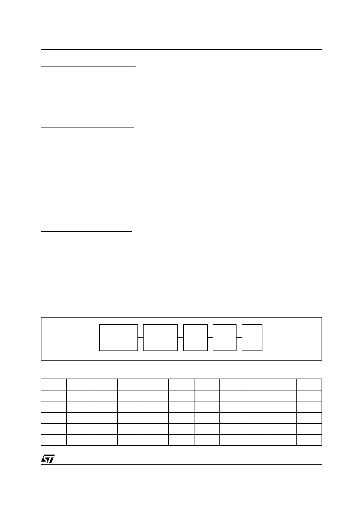
efficiency (n). The test configuration and test results are shown below:
Test Set-Up and Equipment
AC POWER
SOURCE
LARCET 3KW
PM1200
AC POWER
ANALYSER
EMI
FILTER
PFC
L4981
DEMO
LOAD
Table 1. 500W Demoboard Evaluation Results
V
in
Vrms (Hz) (W) (%) (%) (%) (%) (V) (W) (%)
88 60 560 99.9 2.9 1.3 1.7 1.2 402 490 87.5
110 60 543 99.9 2.8 1.4 1.8 1.3 403 492 90.6
220 50 525 99.8 3.3 1 2.4 1.1 4 06 499 95.1
270 50 523 99.8 3.4 1 2.6 1.1 408 504 96.3
f
P
i
PF THD H3 H5 H7
V
out
P
o
η
13/20
Page 14

AN827 APPLICATION NO TE
EMI/RFI FILTER
The harmonic content measurement was made with the EMI/RFI filter interposed between the AC source and
the demoboard under test, while the efficiency has been calculated without the filter contribution.
Figure 1.
EMI/RFI Test Filter
LINE PFC
EARTH
T1 T2
C1
C
D94IN052
Part List of the Figure 2
Part Des. Description Vendor’s Part #
Fuse F1 Fuse, 3AG Fast Acting 10A, 250VAC Digi-Key #F127-ND
Fuse Clip 3AG Fuse Clips Digi-Key #F048-ND
C1 Met. Poly. Film Cap., 0.22µF, 100V Panasonic ECQ-E1224KF Digi-Key #EF1224
C2 Met. Poly. Film Cap., 0.22µF, 100V Panasonic ECQ-E1224KF Digi-Key #EF1224
C3 Met. Poly. Film, .68uF, 250VAC, Panasonic ECQU2A684MV Digi-Key #P4615-ND
C4 Polyester Cap., .001µF, 50V, Panasonic ECQ-B1H102JF Digi-Key #P4551-ND
C5 Polyester Cap., .012µF, 50V Panasonic ECQ-B1H123JF Digi-Key #P4583-ND
C6 Alum. Electrolytic Cap., 330µF, 450VDC, 85°C Digi-Key#P6443-ND
C7 Electrolytic Cap., 1.0µF, 63V, Panasonic ECE-A1JU010,85°C Digi-Key #P6275-ND
C8 Electrolytic Cap., 1.0µF, 63V, Panasonic ECE-A1JU010,85°C Digi-Key #P6275-ND
C9 Polyester Cap. 680pfd., 50V, Panasonic ECQ-B1H681JF Digi-Key # P4580-ND
C10 Met. Poly. Film Cap., 0.22µF, 100V Panasonic ECQ-E1224KF Digi-Key #EF1224
C11 Ceramic Capacitor, 820pfd.,1000VDC Digi-Key #P4127-ND
C12 Electrolytic Cap., 220µF, 25V,Panasonic ECE-A1EU101,85°C Digi-Key #P6240-ND
D1 Diode Bridge, 600V, 25A Digi-Key #MB256-ND
D2 STTA806D/DI,, 600V, 8A, Isolated TO220AC Package STMicroelectronics STTA806D/DI
D3 Switching Diode, 1N4148, 100V Digi-Key #1N4148CT-ND
D4 Fast Recovery Diode, STTB406, 600V, 4A STMicroelectronics STTB406
D5 Zener Diode, 22V, 1/2W, DO-35 Package Digi-Key #1N5251BCT-ND
D6 Zener Diode, 18V, 1/2W, DO-35Package Digi-Key #1N5248BCT-ND
D7 Fast Recovery Rectifier Diode, 100V, 1.5A STMicroelectronics BYW-100-100
D8 Fast Recovery Rectifier Diode, 100V, 1.5A STMicroelectronics BYW-100-100
D9 Fast Recovery Rectifier Diode, 100V, 1.5A STMicroelectronics BYW-100-100
D10 Fast Recovery Rectifier Diode, 100V, 1.5A STMicroelectronics BYW-100-100
R1 Metal Film Res., 806K, 1/4W, 1% Digi-Key #806KXBK-ND
R2 Metal Film Res., 806K, 1/4W, 1% Digi-Key #806KXBK-ND
R3 Carbon Film Res., 33K, 1/4W, 5% Digi-Key #33KQBK-ND
14/20
Page 15

AN827 APPLICATION NOTE
Part List of the Figure 2 (continued)
Part Des. Description Vendor’s Part #
R4 Carbon Film Res., 360k, 1/4W, 5% Digi-Key #360KQBK-ND
R5 Carbon Film Res., 620k, 1/4W, 5% Digi-Key #620KQBK-ND
R6 Carbon Film Res., 620k, 1/4W, 5% Digi-Key #620KQBK-ND
R9 Metal Film Res., 412k, 1/4W, 1% Digi-Key #412KXBK-ND
R10 Metal Film Res., 412k, 1/4W, 1% Digi-Key #412KXBK-ND
R11 Metal Film Res., 21k, 1/4W, 1% Digi-Key #21.0KXBK-ND
R12 Metal film Res., 562, 1/4W, 1% Digi-Key #562XBK-N D
R13 Metal Film Res., 5.11k, 1/4W, 1% Digi-Key #5.11KXBK-ND
R14 Carbon Film Res., 2.7k, 1/4W, 5% Digi-Key #2.7KQBK-ND
R15 Carbon Film Res., 36k, 1/4W, 5% Digi-Key #36KQBK-ND
R16 Carbon Film Res., 2.7k, 1/4W, 5% Digi-Key #2.7KQBK-ND
R17 Metal Film Res., 30.1k, 1/4W, 1% Digi-Key #30.1KXBK-ND
R18 Carbon Film Res., 15 ohms, 1/4W, 5% Digi-Key #15QBK-ND
R19 Carbon Film Res., 120k, 1/4W, 5% Digi-Key #120KQBK-ND
R20 Metal Film Res., 10.7k, 1/4W, 1% Digi-Key # 10.7KXBK-ND
R21 Metal Film Res., 909k, 1/4W, 1% Digi-Key #909KXBK-ND
R22 Metal Film Res., 909k, 1/4W, 1% Digi-Key #909KXBK-ND
R23 Metal Oxide Resistor, 510 ohms, 3 Watts, 5% Digi-Key#P510W-3BK-ND
R24 Metal Oxide Resistor, 510 ohms, 3 Watts, 5% Digi-Key#P510W-3BK-ND
R25 Carbon Film Resistor, 10k, 1/4W, 5% Digi-Key #10KQBK-ND
R26 Carbon Film Resistor, 1.1M, 1/4W, 5% Digi-Key #1.1MQBK-ND
R27 Carbon Film Resistor, 1.1M, 1/4W, 5% Digi-Key #1.1MQBK-ND
R28 Carbon Film Res., 10k, 1/2W, 5% Digi-Key #10KH-ND
R29 Carbon Film Resistor, 33 ohms, 1/2W, 5% Digi-Key #33H-ND
R30 3 Watt, non-inductive 0.1 ohms, Type LO-3-.010 Newark #96F3616
R31 3 Watt, non-inductive 0.1 ohms, Type LO-3-.010 Newark #96F3616
R32 3 Watt, non-inductive 0.1 ohms, Type LO-3-.010 Newark #96F3616
NTC 1 20 Ga (0.8mm) Jumper Wire 22 Ga Jumper
NTC 2 20 Ga. (0.8mm) Jumper Wire 22 Ga Jumper
Heatsink 1 AAVID type 61085, 1.5Deg C/W/3in., 1.5" length AAVID #61085
Heatsink 2 Bridge Diode attachable heatsink datogliere
PCB 1 FR-4 Material CALS 95 001_A
T1 Coilcraft Part# R4849-A 0.5mH CoilCraft ’Part # R4849-A
Standoffs Aluminum Hex Standoff 0.375", 4-40 Thread Newark#89F1949
Q1 STW20NA50, 500V, 20A, 2.7 ohms TO-247 STMicroelectronics STW20NA50
Q2 NPN transistor high speed, 30V, .8A, TO-18 Package STMicroelectronics 2N2222
Q3 N-Channel Mosfet, STK2N50, 500V, 2A, SOT-82 STMicroelectronics STK2N50
J1 3 Pole, 15A, Terminal Block Newark #93F7182
J2 3 Pole, 15A, Terminal Block Newark #93F7182
U1 L4981A, PFC IC STMicroelectronics L4981A
IC Socket 20 Pin DIP Socket, Gold Pin and Clip Digi-Key #ED56203-ND
Misc. Mounting screws, nuts, insulators
15/20
Page 16

AN827 APPLICATION NO TE
Figure 2. 500W Demoboard Schematic
Vout
C6
450V
330µF
R21
909K
R9
412K
D2 STTA806DI
R27
R28
1.1M
R6
R5
R4
10K
5%
620K
620K
360K
-
1/4W
5%
5%
5%
T1
1%
1%
D8
D7
R26
R29
1.1M
1%
R22
909K
1%
R10
412K
D10D9
+
BYW100-100
33
1/4W
Q3
STK2N50
D5
5%
Q2
C2
100V
220nF
R3
5%
33K
1/4W
D6 18V
C12
220µF
22V
1/4W
2N2222
25V
C10
R19
120K 5%
VFEED
R7 R8
PUVLO VCC
R25 10K 5%
220nF
14
19
15
16
S/FM
100V
VAOUT
13
VRMS
OVP
U1
7
C11
D3 1N4148
3
L4981A
4
IPK
IAC
820pF
R18
GDRVMOUT
20
2
R11
R20
1000V
STW20NA50
Q1
15Ω 5%
1
6
11
1217 101895
SSC
8
CAOUT
1%
21K
1%
10.7K
LFF
R13
R23
510Ω
PGND
SGND
VREF
ROSC
COSC
ISENSE
C9
0.68nF 50V
5%
R15 36K
1%
5.11K
3W
C5
C7
12nF
D4
1µF
R16
R14
R24
2.7K
2.7K
50V
3W
510Ω
STTB-406
63V
C8
1µF
63V
1%
R17
30.1K
C4
1nF
50V
5%
R30 0.1Ω 3W
5%
D95IN258B
R31 0.1Ω 3W
R32 0.1Ω 3W
16/20
R1
806K
F1
10A
Vi (88 to 264V)
1%
R2
NTC2
806K
+
1%
D1
C1 220nF 100V
C3
0.68µF
+-
BRIDGE
250VAC
NTC1
R12 562 1%
+
-
Page 17

Figure 3. 500W Demoboard Printed Circuit Board Layout
AN827 APPLICATION NOTE
17/20
Page 18

AN827 APPLICATION NO TE
An Application Program named Designing PFC [3] is available for the designer. This program allows the designer to make changes to the input/output design specifications and calculates and selects the component values
and types. For example, this program can easily convert this design to single mains operation (120 or 240 Volts).
The results are presented in two screens, the schematic and parts list, and may be sent to a printer for a hardcopy for future reference. Two solutions at 110Vac (fig. 4) and 220Vac (fig. 5) are shown below.
Figure 4. 400W/230V; Vin = 110V ± 20V
C6
315V
Vout=230V
680µF
R21
360K
R9
330K
D2 BYT08P-400
-
T1
2W
10K
R28
5%
R27
1.1M
1%
1%
D8
D7
R26
R22
R10
BYW100-100
33
R29
1/4W
Q3
5%
1.1M
1%
360K
1%
330K
D10D9
+
STK2N50
D5
Q2
1/4W
D6 18V
25V
C12
220µF
22V
1/4W
2N2222
R25 10K 5%
R7 R8
R19
220K 5%
VFEED
PUVLO VCC
C10
120nF
14
19
15
16
S/FM
100V
13
OVP
VAOUT
U1
7
VRMS
D3 1N4148
3
L4981A
4
IAC
C11
IPK
330pF
R18
GDRVMOUT
20
2
250V
Q1
15Ω 5%
1
6
11
1217 101895
8
1%
15K
R11
1%
15K
R20
R23
STP9N30
LFF
SSC
CAOUT
R13
5.11K
2W
680Ω
PGND
SGND
VREF
ROSC
COSC
ISENSE
C9
0.47nF 50V
5%
R15 47K
1%
C5
12nF
R24
D4
C7
R17
R16
R14
50V
680Ω
STTB-406
1µF
63V
C8
1µF
1%
24K
C4
1.2nF
5%
6.2K
5%
6.2K
D95IN284C
2W
63V
60V
R30 120mΩ 2W
R31 120mΩ 2W
R32 120mΩ 2W
18/20
R1
200K
F1
10A
Vi (88 to 132V)
R2
1%
NTC2
200K
+
1%
D1
+-
BRIDGE
R12 360 1%
C3
470nF
250VAC
NTC1
+
-
Trasformer T1:
core: ETD 39 x 20 x 13 / gap ≈1.8mm.
Primary Inductance =0.25mH
44 Turns 15 x AWG29.
Secondary = 5 Turns
Page 19

Figure 5. 800W/400V; Vin = 220V ± 20V
C6
470µF
Vout=400V
AN827 APPLICATION NOTE
450V
R21
909K
R9
412K
D2 STTA806DI
R27
R28
1.1M
10K
5%
-
4W
T1
1%
1%
D8
D7
R26
R29
1.1M
1%
R22
909K
1%
R10
412K
D10D9
+
BYW100-100
33
1/4W
STK2N50
Q3
D5
5%
Q2
1/4W
D6 22V
25V
C12
220µF
22V
1/4W
2N2222
R25 10K 5%
R7 R8
R19
130K 5%
VFEED
PUVLO VCC
C10
220nF
14
19
15
16
S/FM
100V
VAOUT
13
VRMS
OVP
U1
7
C11
D3 1N4148
3
L4981A
4
IPK
IAC
820pF
R18
GDRVMOUT
20
2
R11
R20
1000V
Q1
15Ω 5%
1
6
11
1217 101895
SSC
8
CAOUT
1%
21K
1%
10.7K
3W
R23
510Ω
STH14N50/FI
PGND
SGND
LFF
VREF
ROSC
COSC
ISENSE
C9
0.47nF 50V
5%
R15 36K
1%
R13
5.11K
C5
12nF
R24
D4
C7
R17
R16
R14
50V
3W
510Ω
STTB-406
1µF
63V
C8
1µF
1%
24K
C4
1.2nF
5%
7.5K
5%
7.5K
63V
60V
R30 120mΩ 2W
D95IN283C
R31 120mΩ 2W
R32 120mΩ 2W
R1
510K
F1
10A
Vi (176 to 264V)
1%
R2
NTC2
510K
+
1%
D1
+-
BRIDGE
C3
220nF
250VAC
NTC1
+
R12 390 1%
Trasformer T1:
core: ETD 44 x 22 x 14 / gap =2mm.
Primary Inductance =0.43mH
53 Turns 10 x 0.36mm
Secondary = 5 Turns
-
19/20
Page 20

AN827 APPLICATION NO TE
REFERENCES
[1]
G. Comandatore and U. Moriconi, Application Note 628 Designing A High Power Factor Switching
Preregulator With The L4981 Continuous Mode, STMicroelectronics, Inc., STMicroelectronicsMay, 1994.
[2]
Datasheet Power Factor Corrector, STMicroelectronics, Inc., May, 1994.
[3]
Designing PFC Application Program, ST Microelectronics, Inc., April, 1995.
Information furnished is believed to be accurate and reliable. However, STMicroelectronics assumes no responsibility for the consequences
of use of such information nor for any infringement of patents or other rights of third parties which may result from its use. No license is granted
by implic ation or oth erwise under any patent or patent rights of STMicroelectronic s. Specific ations mentioned in this publication are subject
to change without notice. This publication supersedes and replaces all information previously supplied. STMicroelectronics products are not
authorized for use as critical components in life support devi ces or systems wi thout express written ap proval of STMi croelectronics.
The ST logo is a registered tradema rk of STMicroe l ectronics.
All other n am es are the pro perty of their respective owners
© 2003 STMi croelectro ni cs - All rights reserved
Australi a - B elgium - Brazil - Canad a - China - Czech Republic - F i nl and - France - Germany - Hong Kong - India - Is rael - Italy - Japan -
Malaysia - Malta - Morocco - Singapore - Spain - Sweden - Switzerland - United Kingdom - United States
STMicroelectronics GROUP OF COMPANIES
www.st.com
20/20
 Loading...