

Page 1
AN821
APPLICATION NOTE
NEW LAYOUT INSULATION REQUIREMENT
INTRODUCTION
In order to assume better level of security for telecommunication system users, some new rules have been
published. This is the case of the IEC950 standard which dedicates one chapter to this subject. This kind
of requirement is beginning to be active in Germany for example.
REQUIREMENT
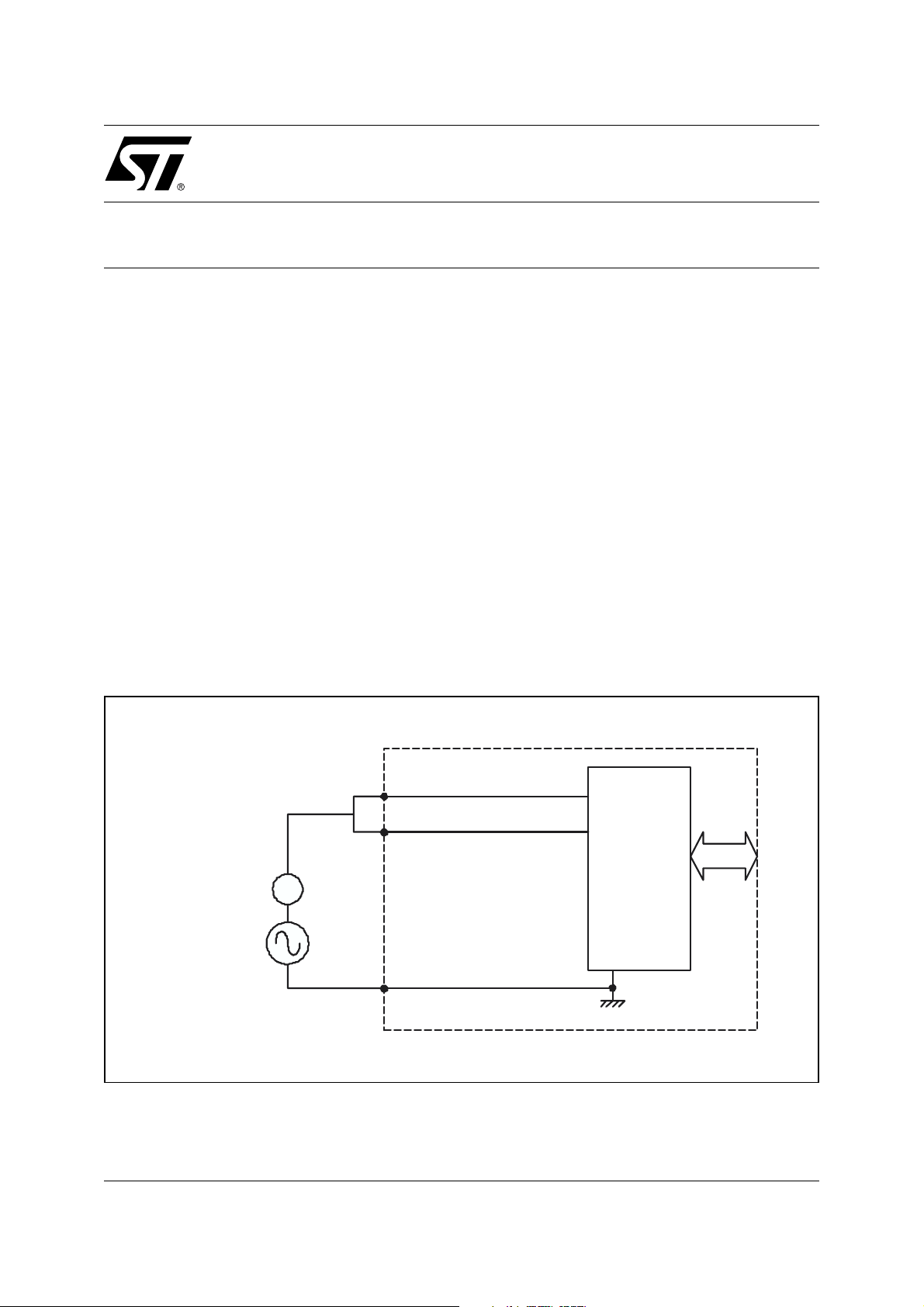
Figure 1 shows the principle of the test circuit. The test consists of the insulation measurement of the telecommunication network and the earth. During this test it is permitted to remove components. In fact in the
field the procedure is done as follow:
– The protection device is removed from the board.
– The telecommunication lines are connected together. Tip and Ring lines from all the subscribers for an
exchange equipment, or A and B lines for a telephone set.
– A voltage of 2 kV is applied between the lines and ground.
– The current flowing in the test circuit shall not exceed the requested limit, for example 10 mA in the
IEC950 case.
Figure 1. Test Circuit
TEST
GENERATOR
mA
TELECOM. EQUIPMENT
REV. 2
1/4May 2004
Page 2
AN821 APPLICATION NOTE
OUR PROPOSAL
To withstand these new requirements STMicroelectronics proposes an adapted input/output arrangement
for the THBT series.
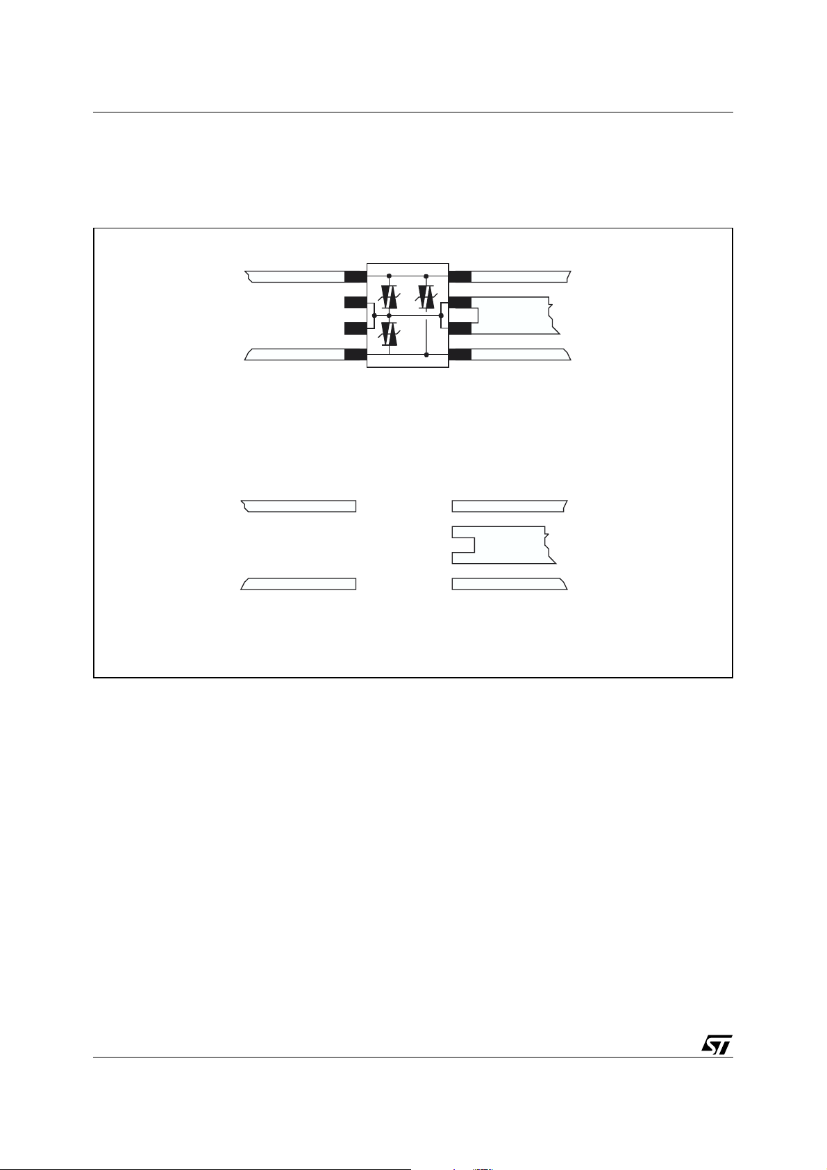
Figure 2. STMicroelectronics proposal
TIP TIP
TO THE
TELECOM.
NETWORK
TO THE
TELECOM.
NETWORK
RING
RING
WITH COMPONENT ON BOARD
TIP TIP
RING
RING
LAYOUT WITHOUT COMPONENT ON BOARD
TO THE
TELECOM.
EQUIPMENT
TO THE
TELECOM.
EQUIPMENT
Figure 2 shows our proposal that consists of following points:
– Insulation between inputs and outputs. For example TIP coming from the telecommunication network
is isolated from the TIP connected to the sensitive part of the circuit. That means, when the surge
suppressor is removed, no current can flow through the telecommunication equipment.
– For the component which has got four ground pins (like the THBT200xx), only two pins are enough to
withstand the maximum surge current capability of the component. That means only the two ground
pins located on the telecommunication equipment side are connected.
SUMMARY
New standards concerning the protection of the telecommunication network service personnel, and other
users of this network, from hazards in the equipment seems to be generalized. STMicroelectronics has
taken into account this fact and proposes to meet these requirements by layout like shown in Figure 2.
2/4
Page 3

REVISION HISTORY
Table 1. Revision History
Date Revision Description of Changes
June-1995 1 First Issue
10-May-2004 2 Stylesheet update. No content change.
AN821 APPLICATION NOTE
3/4
Page 4

AN821 APPLICATION NOTE
Information furnished is believed to be accurate and reliable. However, STMicroelectronics assumes no responsibility for the consequences
of use of such information nor for any infringement of patents or other rights of third parties which may result from its use. No license is granted
by implication or otherwise under any patent or patent rights of STMicroelectronics. Specifications mentioned in this publication are subject
to change without notice. This publication supersedes and replaces all information previously supplied. STMicroelectronics products are not
authorized for use as critical components in life support devices or systems without express written approval of STMicroelectronics.
The ST logo is a registered trademark of STMicroelectronics.
All other names are the property of their respective owners
© 2004 STMicroelectronics - All rights reserved
STMicroelectronics GROUP OF COMPANIES
Australia - Belgium - Brazil - Canada - China - Czech Republic - Finland - France - Germany - Hong Kong - India - Israel - Italy - Japan -
Malaysia - Malta - Morocco - Singapore - Spain - Sweden - Switzerland - United Kingdom - United States
www.st.com
4/4
 Loading...