

Page 1

®
AN676
APPLICATION NOTE
Battery charger using the ST6-REALIZER
INTRODUCTION
Because competition becomes greater and greater it is important to reduce time to market.
The ST6 Realizer helps to fullfill this duty. The time needed to realize a design is dramatically
reduced. Design of an application takes a few days instead of a few weeks.
Users who develop ST6 applications are systems electronics engineers; Often they do not
know the assembler well and there are reluctant to use it. The ST6 Realizer allows users to
design their applications using symbols known by hardware designers such as comparators,
counters, multiplexers. Once the design is over, the ST6 Realizer generates assembly code or
executable code for the different ST6 target hardware.
June 2008 Rev 2 1/14
Page 2

BATTERY CHARGER USING THE ST6-REALIZER
APPLICATION NOTE GOAL
This note aims at introducing the different features of the ST6 Realizer graphic tool. It is also a
tutorial to firstly help you get started with ST6 Realizer design, then for you to implement
advanced features to optimize your design or to evaluate the target hardware requirements.
The application note describes a battery charger because it illustrates the different features of
the ST6 Realizer throughout it. The charger implements a simple charging method.
Nevertheless charging end points using the negative voltage slope detection method or voltage
inflection points can be implemented with this battery charger ST6 board.
HARDWARE SCHEMATICS
The schematics describes the different hardware parts of the application:
The microcontroller connections
The power supply
The charging indicators
The start push button
The power command
2/14
Page 3

BATTERY CHARGER USING THE ST6-REALIZER
Figure 1 : Simple Battery Charger Circuit Schematic
HIGH
POWER SUPPLY
J1 JACK
GND
Battery cell: AA type / 1.2V - 0.5Ah
GND
22MF
C1
VCC
R10
470
R2
LOW
R8
470
T1
CURRENT
VOLTAGE
68 ohms
GND
U1
10 ohms
R4
BATTERY
NiCd BATTERY
BT1
2 ohms
R6
BD236-PNP-45V
GND
T3
7805
IMAX
VCC
GND
MAX CURRENT
ADJUST
RV1
50K-RV
READY
LED_LO
LED_HI
8MHZ-XT-P
GND
C310pF
GND
10pF
XT1
C2
1MF
CHARGE CURRENT
INDICATOR
LD3
LED-RED-5MM
LED-RED-5MM
LED-RED-5MM
LD2
LD1
GND
GND
470
GND
START PUSH-BUTTON
SW1
R1
470
R2
470
R7
START
C4
VCC
CURRENT
VOLTAGE
ST6210/20 MCU
IMAX
GND
6
7
8
9
10
ST6210
NMI
TEST
RESET/
PB7
PB6
PB5
PB411PB312PB213PB114PB015PA316PA217PA118PA019VSS
START
HIGH
LOW
100K
4
5
OSCOUT
LED_LO
DISCHRG
VCC VDD
1
2
3
U2
TIMER
OSCIN
20
READY
LED_HI
Note that in the circuit diagram the Microcontroller is shown as a simple box. The objective of
the ST6 Realizer is to enable you to write the program code for the microcontroller with the
same ease and in the same manner as you have drawn the hardware schematic.
3/14
Page 4

BATTERY CHARGER USING THE ST6-REALIZER
Figure 2 : Functional Diagram
Start
Imax
READY
HIGH
Icharge
Vcharge
The MCU manages all the functions of the application:
At reset the READY LED blinks to indicate that the charger is ready to charge.
The user pushes the START button to begin the HIGH charge.
The READY LED switches off. The HIGH LED highlights.
The LOW charge takes place when the VOLTAGE threshold of 1.5 V is reached.
The HIGH LED switches off. The LOW LED switches on.
The battery charge is over when the delay of LOW charge is reached.
The LOW LED switches off. The READY LED blinks.
When the current in the battery is too high, HIGH charge or LOW charge are bypassed.
MCU
LOW
HIGH CHARGE
LOW CHARGE
4/14
Page 5

Figure 3 : Flow Chart
BATTERY CHARGER USING THE ST6-REALIZER
Start
HIGH charge
Voltage > 1,5V
Yes
LOW charge
Charging time
expired
Yes
No
Current Too High
No
No
No
Current Too High
Yes
5/14
Page 6

BATTERY CHARGER USING THE ST6-REALIZER
HARDWARE RESOURCES
The application can run in stand-alone mode using an ST6215 microcontroller. It can be driven
by the ST622X, ST624X, ST626X Starter Kit.
The microcontroller requires:
3 analog inputs for:
Imax: the maximum current
Icharge: the charging current
Vcharge the actual voltage at the + connection of the cell
a digital input to connect the start push button
2 digital outputs to switch the LOW charge current and the HIGH charge current
3 digital outputs to switch the three LEDs that supply the user with information status
SOFTWARE DESIGN
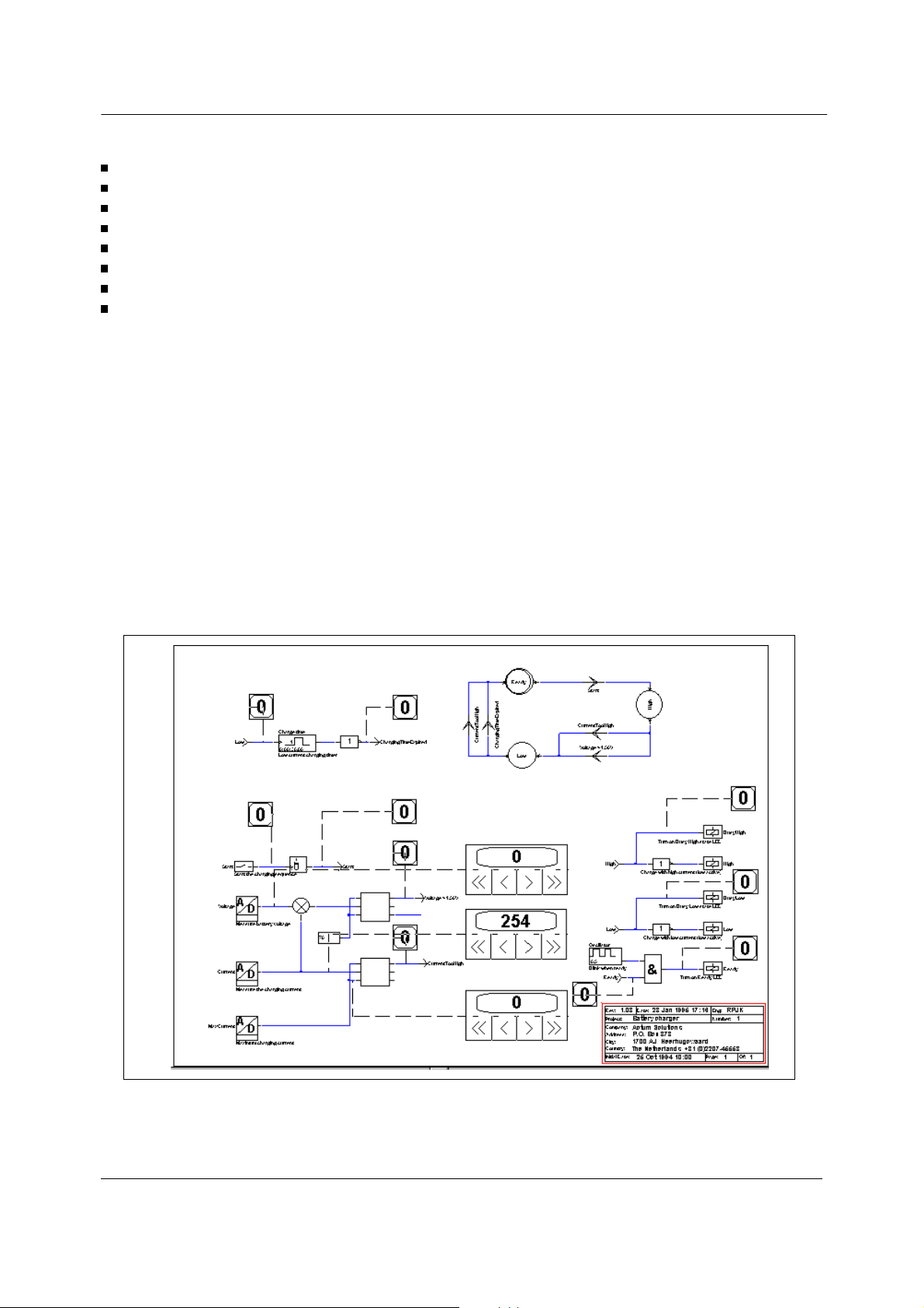
The flow chart is implemented in the schematic editor of the Realizer as a state machine.
Figure 4 : State Machine
The state machine sums up the behaviour of the application. Due to the fact that the ST6
Realizer is a graphic tool, it is easy to explain how the application works with symbols and state
machines.
Symbols named condition are events that allow the switching from state to state.
The condition symbols are connected either to an external input (Start, CurrentTooHigh,
Voltage>1.5V) or to internal outputs (ChargingTimeExpired).
Symbols named state are linked to actions. In this application:
HIGH STATE starts high charging current and switches on high level status LED
LOW STATE starts low charging current and switches on low level status LED
READY STATE indicates by blinking an LED that the charge is over or the application is
waiting for a new battery to be charged.
6/14
Page 7

BATTERY CHARGER USING THE ST6-REALIZER
Software schematics
internal output & internal input condition
external input conditions
external output actions
Figure 5 : Internal Output & Internal Input Condition
Figure 6 : External Input Conditions
7/14
Page 8

BATTERY CHARGER USING THE ST6-REALIZER
Figure 7 : External Output Actions
Selecting the I/O
Symbols such as digin, digout or ADC are connected to I/O pin ports. By selecting the target
hardware and by double clicking on the symbol it is possible to assign a pin port to this symbol
and to program it respectively as a digital input, a digital output or an analog input.
The realizer process
It is of interest to know how the ST6 Realizer works to avoid misunderstandings about the
design application .
Here is how the realizer builds up its code:
general definitions, like device name, registers
reset entry
initialisation of the port registers according to the connections made in the ST6 Realizer
create backup register for output ports
initialisation of the AD converter
initialisation of the timer for the 10 ms tick
initialisation of the RAM used by the Realizer application.
call symbols initialisation macros
start of the main loop (Realmain)
restart the AD converter when it is ready
read the number of 10ms ticks and copy them for use by the ST6 Realizer application
call symbol main macros, first all input symbol macros then all "normal" symbol macros and
finally the output symbol macros.
8/14
Page 9
BATTERY CHARGER USING THE ST6-REALIZER
call state machine macros
call edge-sensitive input macros
copy the backup values to the output ports
trigger the watchdog if this option is enabled
jump to the start of the loop (Realmain)
AD converter interrupt routine
timer 10ms interrupt routine
interrupt vector table
Generating code
Before generating the ST6 program code it is necessary to define the target hardware where
the executable code will be loaded. The ST6210 microcontroller suits the application well. Then
the analyse step is run with all the selected options to get the executable code.
Debugging the application
Once the design of the application is over, the the executable code is available. The next step
is to verify that the design corresponds to the design specifications. The validation of the design
is made with the simulator.
In the application state machine items are involved with the inputs and outputs of the system.
The way to debug the application is to verify that each condition activates the corresponding
state machine.
Figure 8 : Debugging Scheme With The Simulator
9/14
Page 10

BATTERY CHARGER USING THE ST6-REALIZER
The external inputs of the system are connected to adjusters. In this way it is easy to activate
the system. Numeric adjusters are used to get fixed input values. It is forbiden to put probes on
the state machine, however they can be put on the statein and stateout symbols.
At reset it is interesting to set adjusters to inactive values and to verify that the application
states are inactive but the initial state.
Then adjusters are activated with fixed values so that the system can react to external
stimulation. At this point it is useful to choose the step by step mode to detect spurious state
transitions and to verify state sequences.
It is advised to use host time instead of target time for time transitions because it takes less
time. But for benchmark timing it is more convenient to choose the target time to keep the
compatibility between instruction execution and time calculation. This information is given by
the information loop box.
Once the schematics has been tested, the executable code can be programmed into an
EPROM-based version of the ST6 microcontroller using the ST6 Starter Kits or EPROM
programmers.
10/14
Page 11

BATTERY CHARGER USING THE ST6-REALIZER
HARDWARE CONSTRAINTS
It is found that the real application in stand alone mode does not work as well as the simulated
application. The battery charge goes directly into low level current without charging the battery.
The problem is identified as coming from voltage fluctuations .
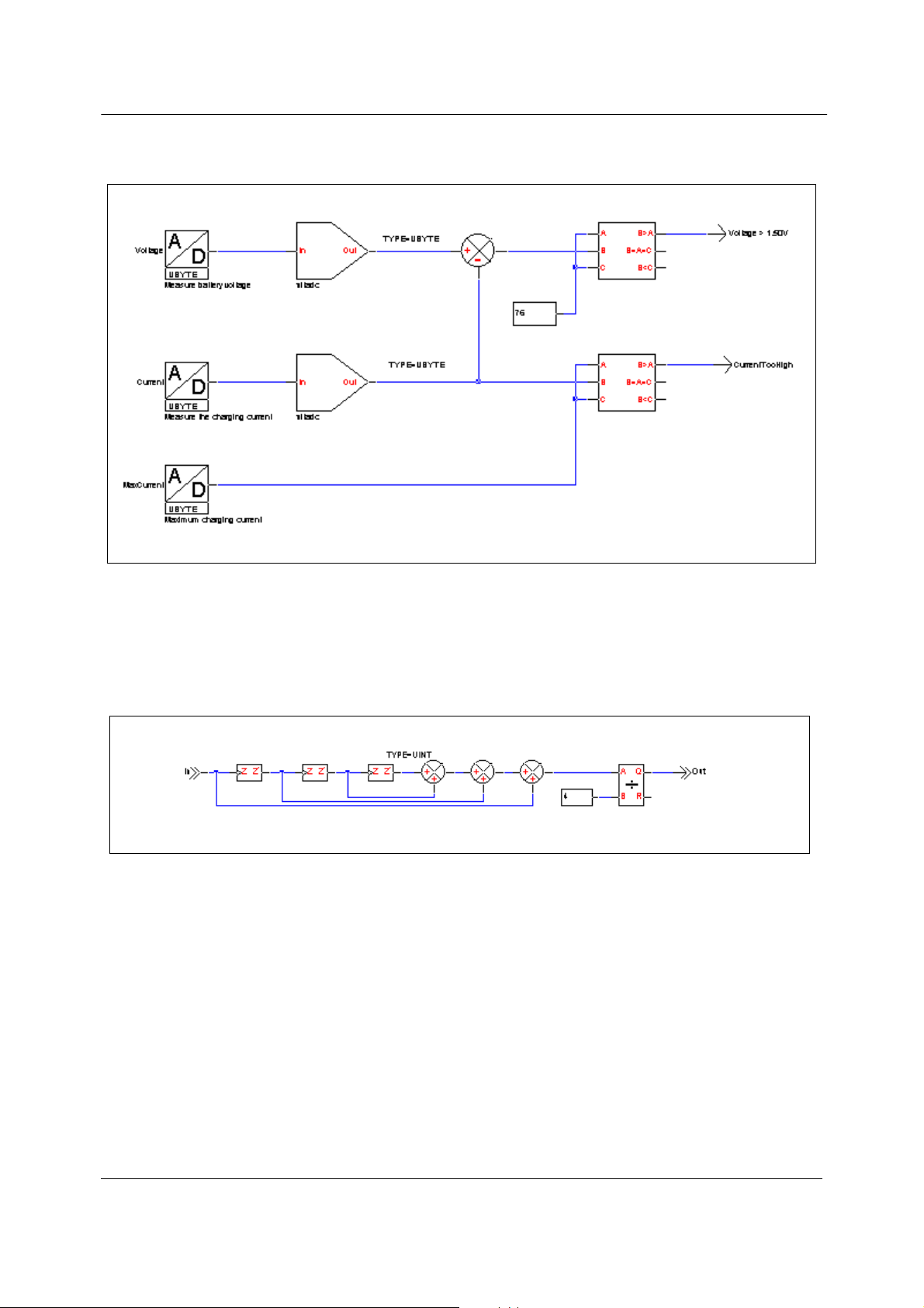
The first solution
The first solution considered was to average the ADC values to decrease the influence of the
voltage fluctuations. The average is designed in the figure below :
Figure 9 : Averaging Scheme
It takes four loops before the ADC voltage can be correctly averaged every loop. The input of
the first add2 symbol must be cast to UINT type because the output can be superior to an
UBYTE type. This way the UINT type is expanded to all following symbols.
In real terms it takes less than 1ms to run a loop. So it takes less than 4 ms to get a correct
average voltage. In addition the start push button must not be pressed while the average is not
stabilized.
The schematic design for the average is quite large. As it must be implemented on the ADC
that converts the charging current and the voltage, the root scheme drawing will be overloaded
with symbols and be confusing to read. On the other hand, the implementation of these ADC
converters is memory consuming. These drawbacks have been solved by creating
sub-schemes. The figure below shows the use of sub-schemes:
11/14
Page 12
BATTERY CHARGER USING THE ST6-REALIZER
Figure 10 : Use Of Sub-Schemes
The output of the sub-scheme symbol is cast to UBYTE type because the average result fits to
the values of an unsigned byte. In addition it is not worth keeping UINT 16-bit type because it
wastes RAM memory.
Inside the sub-scheme the treatment of the average looks like this:
Figure 11 : A Generic Averaging Sub-Scheme
The symbols portin and portout allow the sub-scheme to be link ed to the root scheme. The
label of portin and portout must match the names of the sub-scheme symbol.
While ADC values were averaged the behaviour of the real application were the same.The High
current charge did not occur.
Second solution
The use of a numeric oscilloscope proves that the problem came from voltage fluctuations that
occur during the establishment of the high current charging circuit. This problem is solved by
adding a new state to invalidate the voltage threshold during the setup time of the high current
charge. The new state is connected to a fixed timer whose duration is the setup time of the high
current charge.
12/14
Page 13

BATTERY CHARGER USING THE ST6-REALIZER
CONCLUSION
The ST6 Realizer is a powerful graphic tool that aims at designing software without requiring
knowledge of assembly language. It uses symbols that hardware designers know well. Another
advantage is that users can develop their application independently from the hardware board.
The ST6 simulator is included in the ST6 Realizer, so that users can validate their design
without the ST6 board. Many applications in automotive and home appliances can be
developped with the ST6 realizer.
13/14
Page 14

BATTERY CHARGER USING THE ST6-REALIZER
Revision History
Date Revision Description of changes
March-1995 1 Initial release
30-June-2008 2 Logo modified
Please Read Carefully:
Information in this document is provided solely in connection with ST products. STMicroelectronics NV and its subsidiaries (“ST”)
reserve the right to make changes, corrections, modifications or improvements, to this document, and the products and services
described herein at any time, without notice.
All ST products are sold pursuant to ST’s terms and conditions of sale.
Purchasers are solely responsible for the choice, selection and use of the ST products and services described herein, and ST
assumes no liability whatsoever relating to the choice, selection or use of the ST products and services described herein.
No license, express or implied, by estoppel or otherwise, to any intellectual property rights is granted under this document. If any
part of this document refers to any third party products or services it shall not be deemed a license grant by ST for the use of such
third party products or services, or any intellectual property contained therein or considered as a warranty covering the use in any
manner whatsoever of such third party products or services or any intellectual property contained therein.
UNLESS OTHERWISE SET FORTH IN ST’S TERMS AND CONDITIONS OF SALE ST DISCLAIMS ANY EXPRESS OR IMPLIED
WARRANTY WITH RESPECT TO THE USE AND/OR SALE OF ST PRODUCTS INCLUDING WITHOUT LIMITATION IMPLIED
WARRANTIES OF MERCHANTABILITY, FITNESS FOR A PARTICULAR PURPOSE (AND THEIR EQUIVALENTS UNDER THE
LAWS OF ANY JURISDICTION), OR INFRINGEMENT OF ANY PATENT, COPYRIGHT OR OTHER INTELLECTUAL PROPERTY
RIGHT.
UNLESS EXPRESSLY APPROVED IN WRITING BY AN AUTHORIZED ST REPRESENTATIVE, ST PRODUCTS ARE NOT
RECOMMENDED, AUTHORIZED OR WARRANTED FOR USE IN MILITARY, AIR CRAFT, SPACE, LIFE SAVING, OR LIFE
SUSTAINING APPLICATIONS, NOR IN PRODUCTS OR SYSTEMS WHERE FAILURE OR MALFUNCTION MAY RESULT IN
PERSONAL INJURY, DEATH, OR SEVERE PROPERTY OR ENVIRONMENTAL DAMAGE. ST PRODUCTS WHICH ARE NOT
SPECIFIED AS "AUTOMOTIVE GRADE" MAY ONLY BE USED IN AUTOMOTIVE APPLICATIONS AT USER’S OWN RISK.
Resale of ST products with provisions different from the statements and/or technical features set forth in this document shall
immediately void any warranty granted by ST for the ST product or service described herein and shall not create or extend in any
manner whatsoever, any liability of ST.
ST and the ST logo are trademarks or registered trademarks of ST in various countries.
The ST logo is a registered trademark of STMicroelectronics. All other names are the property of their respective owners.
Australia - Belgium - Brazil - Canada - China - Czech Republic - Finland - France - Germany - Hong Kong - India - Israel - Italy -
Japan - Malaysia - Malta - Morocco - Singapore - Spain - Sweden - Switzerland - United Kingdom - United States of America
Information in this document supersedes and replaces all information previously supplied.
© 2008 STMicroelectronics - All rights reserved
STMicroelectronics group of companies
www.st.com
14/14
 Loading...