

Page 1
AN590
APPLICATION NOTE
PWM GENERATION WITH ST62 AUTO-RELOAD TIMER
by Microcontroller Division Applications
INTRODUCTION
This note des cribe s how to u se th e ST 62 A uto -re load Tim er ( AR Tim er) to g ene rate a PW M
signal with tunable frequency an d duty cycle. As an examp le, the genera tion of a 31.25 kHz
PWM signal with duty cycle proportional to an analog input voltage is presented.
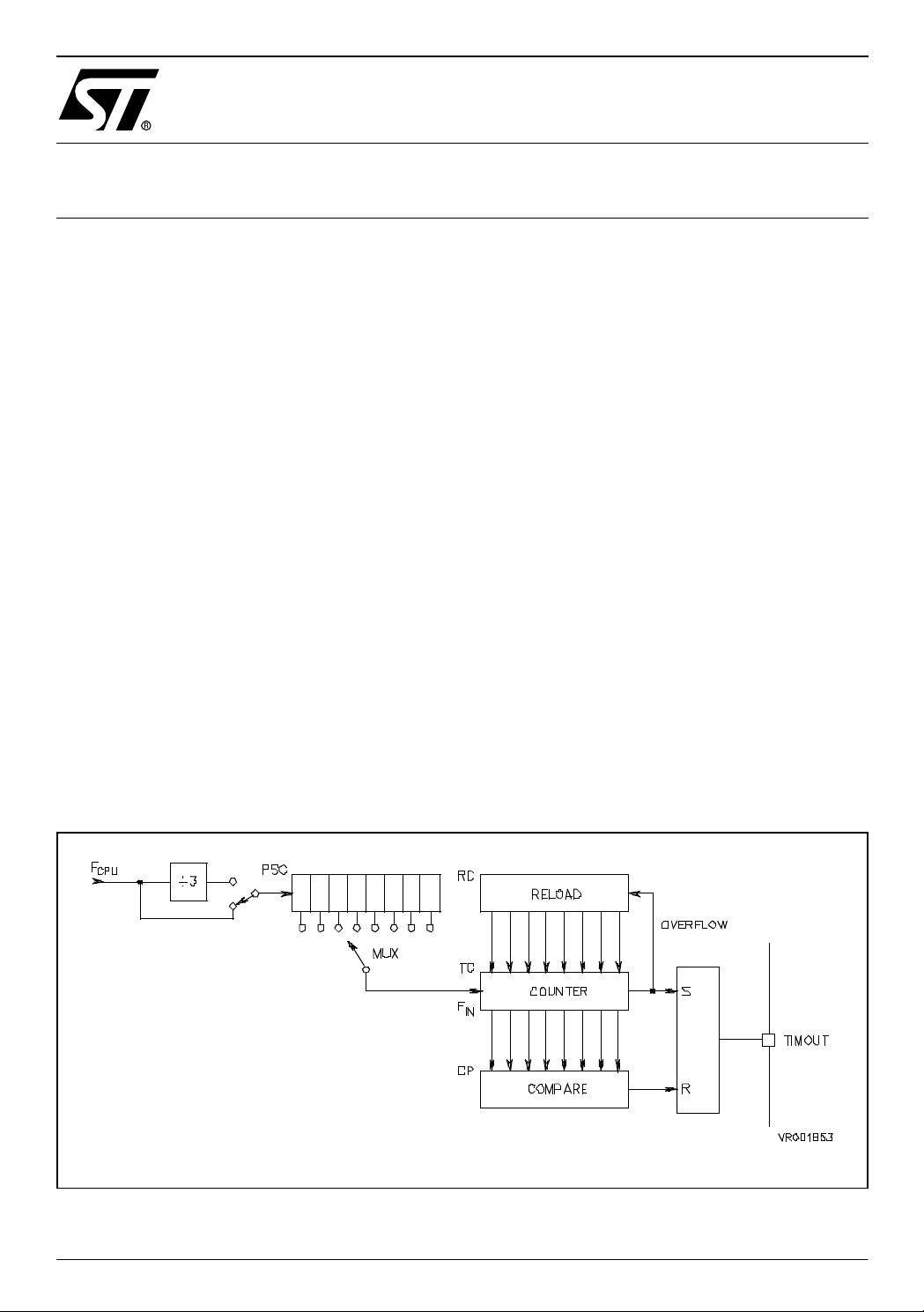
Auto-reload Timer description
This timer is an 8 bit timer/counter with prescaler. It includes auto-reload PWM, capture and
compare capability with one input and one output pin. It is controlled by the following registers
(8 bit):
– Mode Control Register (MC)
– Status registers (SC0, SC1)
– Load register (LR)
– Incremental counter register (TC)
– Compare register (CP)
– Reload/Capture register (RC)
It can also wake up the MCU from wait mode and exit from stop m ode if an external event is
present on the input pin. The prescaler ratio can be programmed to choose the timer input frequency F
(see Table 1).
IN
Figure 1. Aut o- reload Timer Block Diagr am
AN590/0703 1/7
1
Page 2
PWM GENER ATION WITH ST62 AUT O- RELOAD TIMER
Pulse Width Modulation (PWM) Generation
Using the PWM gen eration ca pability of the AR -Timer, th e micro contro ller CPU has only to
start/stop the time r and update the duty cycle. High s peed PWM signals in th e range of
100kHz can be generated. The timer clock input frequency
clock f
and the prescaler ratio. The PWM signal period is controlled by the Reload register.
osc
can be selected by the oscillator
IN
F
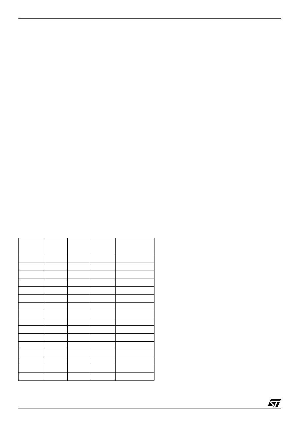
The duty cycle is defined by the Compare register CP (see Figure 2).
The register TC is incremented from RC to 255d, then reloaded at RC to count again. The
PWM output is set on the overflow of TC and reset when TC=CP.
CP can have any valu e betwe en RC and 2 55d. So RC sho uld be m inimal and the presc aler
ratio as small as possible to achieve a maximum resolution.
Major formulae for PWM generation are:
F
IN
F
PWM
= f
/ (prescaler ratio)
osc
= FIN / (256 - RC)
Duty cycle: (CP -RC) / (256 - RC)
Resolution: 1 / (256 - RC)
With a 8MHz oscillator and a pre scaler ratio of 1, the m aximum resol ution (1/256) leads to a
PWM frequency F
of 31.25kHz. A resolution of 1/64 allows to increase F
PWM
to 125kHz.
PWM
Table 1. Prescaler Programming Ra tio
Bit 0
PS2 PS1 PS0
Reg.SC1
0000 1
0001 2
0010 4
0011 8
0100 16
0101 32
0110 64
0111 128
1000 3
1001 6
1010 12
1011 24
1100 48
1101 96
1110 192
1111 384
PRESCALER
Ratio
2/7
2
Page 3
Figure 2. PWM Timer Operation
PWM GENERAT ION WITH ST62 AUTO-RELOAD TIMER
Example 1 :
Target: Generate a 12kHz PWM signal with a duty cycle of 37%, using an oscillator frequency
of 4MHz:
We want to generate a periodic signal at a frequency of 12 kHz and a duty cycle of 37% .
The CPU frequency (quartz frequency) is 4 MHz.
Let’s try with a prescaler ratio of 3:
= 4 MHz / 3 = 1333.33 kHz
F
IN
12 kHz = 1333.33 kHz / (256d - RC)
gives RC = 144.889, rounded to 145
Resolution = 1 /(256 - 145) = 1 / 111
Duty cycle desired: 37%
0.37 = (CP - 145) / (256 - 145) yields CP = 186.07, rounded to 186.
Summary: p resc aler = 3 , R C = 14 5d, CP = 18 6d: the se nu mbers yi eld a PW M freque nc y of
12.012 kHz, a duty cycle of 36.94 % and a resolution of 0.9 %, which is very cl ose to the init ial
goal.
3/7
Page 4

PWM GENER ATION WITH ST62 AUT O- RELOAD TIMER
Program example:
– SC0 is not programmed, so it keeps its reset value 00h (all flags cleared)
– The PWM signal starts as soon as the last instruction (ldi MC) is executed
Program example
****************** A-R Timer Register Set ********************************
RC .def 0D9h,0FFh,0FFh ;reload/capture register
CP .def 0DAh,0FFh,0FFh ;compare register
MC .def 0D5h,0FFh,0FFh ;mode control register
SC0 .def 0D6h,0FFh,0FFh ;status/control register 0
SC1 .def 0D7h,0FFh,0FFh ;status/control register 1
LR . def 0DBh,0FFh,0FFh ;load register
;============================================================
ldi CP, 186 ;compare register = 186d
ldi RC, 145 ;reload register = 145d
ldi SC1,001h ;clock source= CPU clock divided by 3
;prescaler ratio = 1
ldi MC, 11100000b ;auto-reload mode,interrupts disabled
;PWMOUT enabled, start timer
Example 2:
Target: genera te a PWM sign al of frequency 31 .25 kHz with a dut y cycle proportio nal to an
input analog voltage v arying between 0V and V
: 0V corresponds to 0% duty cycle, V
CC
CC
cor-
responds to 100% duty cycle. The CPU clock is 8 MHz:
Referring to example 1, we find that the prescaler ratio must be 1, the value in RC must be 0
and the value in CP is taken directly from the A/D output (varying from 0 to 255d depending
upon the analog input):
RC = 0
CP = 0...255d
prescaler ratio = 1
= 8 MHz
F
IN
= 8 MHz / 256 = 31.25 kHz
F
PWM
Duty cycle = CP / 256d
Resolution = 1/256d = 0.39 %
We need to implement a software loop which repetitively converts the analog input to a digital
value and copies this digital value into CP:
4/7
Page 5

PWM GENERAT ION WITH ST62 AUTO-RELOAD TIMER
Program example
A .def 0FFh,0FFh,0FFh ;Accumulator
;************** Port Register Set ************************************
PA .def 0C0h,0FFh,0FFh ;Data Register Port A
PADIR .def 0C4h,0FFh,0FFh ;Data Direction Reg. Port A
PAOPT .def 0CCh,0FFh,0FFh ;Option Register Port A
;**************** Timer Register Set *********************************
RC .def 0D9h,0FFh,0FFh ;reload capture register
CP .def 0DAh,0FFh,0FFh ;compare Register
MC .def 0D5h,0FFh,0FFh ;mode control register
SC0 .def 0D6h,0FFh,0FFh ;status control register 0
SC1 .def 0D7h,0FFh,0FFh ;status control register 1
LR .def 0DBh,0FFh,0FFh ;load register
;********************* ADC Register Set ******************************
ADCC .def 0D1h,0FFh,0FFh ;adc control register
ADC .def 0D0h,0FFh,0FFh ;adc result Register
;********************* MAIN *******************************************
;port A must be an IOP3 type (port with analog input mode):
ldi PADIR,000h
ldi PAOPT,001h ;PA0 is the analog input
ldi PA, 001h ;PA1..PA7 are input with pull-up
ldi SC1,00000000b ;PSC divides by 1
ldi CP,080h ;compare register = 128d
;(initial duty = 50%)
ldi RC,000h ;reload register = 0
;(count up from 0 to 255)
ldi MC,11100000b ;auto-reload mode,interrupt disabled
;PWMOUT enabled, start timer with
;duty cycle 50% at start-up
adc_loop
ldi ADCC,030h ;start A/D conversion
wt_eoc
jrr 6,ADCC,wt_eoc ;wait for end-of-conversion
ld A,ADC ;save result into Accumulator
ld CP,A ;copy it into CP register
jp adc_loop ;do it again
5/7
Page 6

PWM GENER ATION WITH ST62 AUT O- RELOAD TIMER
The length of the loop “ adc_loop” is the interval at which the duty cycle of the PWM signal will
be updated. In this example, this loop lasts around 76µs, so the PW M du ty cy cle is updated
every 2 or 3 PWM cycles.
Calculation of the 80µs:
- Instruct ions ldi, ld and jp last 4 cycles of 13 clock periods -> 4 x 4 x 13 8MHz periods =
26µs
- Instruction jrr lasts as long as the A/D takes to do the conversion, which is around 50µs at
8MHz -> total length of adc_loop at 8 MHz = approx. 76µs
This last example shows that, as requested, the CPU is not used to generate the PWM signal,
but only to start/stop it and to update the duty cycle.
6/7
Page 7

PWM GENERAT ION WITH ST62 AUTO-RELOAD TIMER
“THE PRESENT NOTE WHICH IS FOR GUIDANCE ONLY AIMS AT PROVIDING CUSTOMERS WITH INFORMATION
REGARDING THE IR PRO DUCT S IN OR DER FO R THEM TO SAV E TIME . AS A RES ULT, STMIC ROEL ECTR ONI CS
SHALL NOT BE HELD LIABLE FOR ANY DIRECT, INDIRECT OR CONSEQUENTIAL DAMAGES WITH RESPECT TO
ANY CL AIM S AR IS IN G FR OM T HE CO N TENT OF S UC H A NO TE A ND /O R T HE U SE M AD E BY C US TO ME RS O F
THE INFORMATION CONTAINED HEREIN IN CONNECTION WITH THEIR PRODUCTS.”
Information furnished is believed to be accurate and reliable. However, STMicroelectronics assumes no responsibility for the consequences
of use of such information nor for any infringement of patents or other rights of third parties which may result from its use. No license is granted
by implic ation or otherwise under any patent or patent ri ghts of STM i croelectr oni cs. Spec i fications mentioned i n this publication are subje ct
to change without notice. This publication supersedes and replaces all information previously supplied. STMicroelectronics products are not
authorized for use as cri tical comp onents in life support dev i ces or systems wi thout the express written approv al of STMicroel ectronics.
The ST logo is a registered trademark of STMicroelectronics
2003 STMicroelectronics - All Rights Reserved.
STMicroelectronics Group of Compan i es
http://www.s t. com
Purchase of I
2
C Components by STMicroelectronics conveys a license under the Philips I2C Patent. Rights to use the se components in an
2
I
C system i s granted pro vi ded that the sy stem conforms to the I2C Standard Specification as defined by Philips.
Australi a - B razil - Canada - China - Finl and - France - Germany - Hong Kong - Ind ia - Israel - Italy - Japan
Malaysi a - M al ta - Morocco - Singapore - Spain - Sw eden - Switz erland - United Kingdom - U.S.A.
7/7
 Loading...