

Page 1

AN4144
Application note
Voltage mode control operation and parameter optimization
By Enrico Poli
Introduction
Voltage mode driving is the stepper motor driving method patented by STMicroelectronics®
which improves the performance of classic control systems.
This driving method performs smoother operation and higher micro-stepping resolutions
and is the best solution for applications where high precision positioning and low mechanical
noise are mandatory.
This application note describes the operating principles of Voltage mode driving and the
strategies for the regulation of the control parameters in order to fit the application
requirements.
The application note also investigates and provides solutions to one of the most common
issues in Voltage mode driving systems: the resonances of the stepper motors.
July 2012 Doc ID 023491 Rev 1 1/28
www.st.com
Page 2

Contents AN4144
Contents
1 Voltage mode driving . . . . . . . . . . . . . . . . . . . . . . . . . . . . . . . . . . . . . . . . 5
1.1 Basic principles . . . . . . . . . . . . . . . . . . . . . . . . . . . . . . . . . . . . . . . . . . . . . 5
1.2 Back EMF compensation algorithm . . . . . . . . . . . . . . . . . . . . . . . . . . . . . . 7
1.3 Motor supply voltage compensation . . . . . . . . . . . . . . . . . . . . . . . . . . . . . 11
1.4 Compensation of thermal drift of the phase resistance . . . . . . . . . . . . . . 12
2 Tuning of the BEMF compensation parameters . . . . . . . . . . . . . . . . . . 13
2.1 Collecting the application characteristics . . . . . . . . . . . . . . . . . . . . . . . . . 13
2.2 First dimensioning . . . . . . . . . . . . . . . . . . . . . . . . . . . . . . . . . . . . . . . . . . 15
2.2.1 Holding, acceleration, deceleration and running currents . . . . . . . . . . . 16
2.2.2 Compensation register values out of range . . . . . . . . . . . . . . . . . . . . . . 17
2.3 Fine tuning . . . . . . . . . . . . . . . . . . . . . . . . . . . . . . . . . . . . . . . . . . . . . . . . 17
2.3.1 Step 1: verify the phase current during the speed sweep . . . . . . . . . . . 18
2.3.2 Step 2: adjust the starting amplitude (KVAL) . . . . . . . . . . . . . . . . . . . . . 18
2.3.3 Step 3: adjust the intersect speed value . . . . . . . . . . . . . . . . . . . . . . . . 19
2.3.4 Step 4: adjust the starting and final slopes . . . . . . . . . . . . . . . . . . . . . . 19
2.3.5 Step 5: final check . . . . . . . . . . . . . . . . . . . . . . . . . . . . . . . . . . . . . . . . . 20
3 Supply voltage compensation guidelines . . . . . . . . . . . . . . . . . . . . . . . 22
4 Thermal drift compensation guidelines . . . . . . . . . . . . . . . . . . . . . . . . 23
5 Stepper motor resonances . . . . . . . . . . . . . . . . . . . . . . . . . . . . . . . . . . . 24
5.1 The effects of the resonances on Voltage mode driving . . . . . . . . . . . . . 24
5.2 Facing resonances . . . . . . . . . . . . . . . . . . . . . . . . . . . . . . . . . . . . . . . . . . 25
5.2.1 Damping resonances using the mechanical load . . . . . . . . . . . . . . . . . 25
5.2.2 Reducing motor current . . . . . . . . . . . . . . . . . . . . . . . . . . . . . . . . . . . . . 26
5.2.3 Skipping the resonance points increasing the acceleration . . . . . . . . . . 26
6 Revision history . . . . . . . . . . . . . . . . . . . . . . . . . . . . . . . . . . . . . . . . . . . 27
2/28 Doc ID 023491 Rev 1
Page 3

AN4144 List of figures
List of figures
Figure 1. Motor phase electrical model . . . . . . . . . . . . . . . . . . . . . . . . . . . . . . . . . . . . . . . . . . . . . . . . 6
Figure 2. Phasor representation of motor phase equation. . . . . . . . . . . . . . . . . . . . . . . . . . . . . . . . . . 6
Figure 3. BEMF compensation curve. . . . . . . . . . . . . . . . . . . . . . . . . . . . . . . . . . . . . . . . . . . . . . . . . . 9
Figure 4. Maximum output current limitation example . . . . . . . . . . . . . . . . . . . . . . . . . . . . . . . . . . . . 10
Figure 5. Supply voltage compensation system . . . . . . . . . . . . . . . . . . . . . . . . . . . . . . . . . . . . . . . . 11
Figure 6. Phase inductance measurement . . . . . . . . . . . . . . . . . . . . . . . . . . . . . . . . . . . . . . . . . . . . 14
Figure 7. Bad k
Figure 8. Good k
Figure 9. Running current limit . . . . . . . . . . . . . . . . . . . . . . . . . . . . . . . . . . . . . . . . . . . . . . . . . . . . . . 16
Figure 10. Speed sweep with first dimensioning parameters . . . . . . . . . . . . . . . . . . . . . . . . . . . . . . . 18
Figure 11. Evaluation of the optimal intersect speed value . . . . . . . . . . . . . . . . . . . . . . . . . . . . . . . . . 19
Figure 12. Tuned starting slope value . . . . . . . . . . . . . . . . . . . . . . . . . . . . . . . . . . . . . . . . . . . . . . . . . 20
Figure 13. Tuned final slope value. . . . . . . . . . . . . . . . . . . . . . . . . . . . . . . . . . . . . . . . . . . . . . . . . . . . 20
Figure 14. Final check acquisition showing artifacts . . . . . . . . . . . . . . . . . . . . . . . . . . . . . . . . . . . . . . 21
Figure 15. Magnified acquisition verifies the presence of artifacts . . . . . . . . . . . . . . . . . . . . . . . . . . . 21
Figure 16. Position ripple caused by the step change . . . . . . . . . . . . . . . . . . . . . . . . . . . . . . . . . . . . . 24
Figure 17. Phase current distortion . . . . . . . . . . . . . . . . . . . . . . . . . . . . . . . . . . . . . . . . . . . . . . . . . . . 25
Figure 18. Motor stall caused by resonances . . . . . . . . . . . . . . . . . . . . . . . . . . . . . . . . . . . . . . . . . . . 25
measurement waveform . . . . . . . . . . . . . . . . . . . . . . . . . . . . . . . . . . . . . . . . . . . . . 15
e
measurement waveform . . . . . . . . . . . . . . . . . . . . . . . . . . . . . . . . . . . . . . . . . . . . 15
e
Doc ID 023491 Rev 1 3/28
Page 4

List of tables AN4144
List of tables
Table 1. BEMF compensation parameters . . . . . . . . . . . . . . . . . . . . . . . . . . . . . . . . . . . . . . . . . . . . . 8
Table 2. BEMF compensation parameters normalized to the supply voltage (V
Table 3. BEMF compensation register values according to application parameters . . . . . . . . . . . . 15
Table 4. Motor status and BEMF compensation registers relationship. . . . . . . . . . . . . . . . . . . . . . . 16
Table 5. Output current according to the electrical position . . . . . . . . . . . . . . . . . . . . . . . . . . . . . . . 19
Table 6. Document revision history . . . . . . . . . . . . . . . . . . . . . . . . . . . . . . . . . . . . . . . . . . . . . . . . . 27
) . . . . . . . . . . . . 10
BUS
4/28 Doc ID 023491 Rev 1
Page 5

AN4144 Voltage mode driving
1 Voltage mode driving
This section describes the basic principles of Voltage mode driving and its implementation in
STMicroelectronics devices with a focus on the compensation of:
● The back electromotive force (Section 1.2)
● The motor supply voltage variation (Section 1.3)
● The thermal drift of the phase resistance (Section 1.4).
1.1 Basic principles
The classic current mode driving method limits the phase current to a reference value using
a comparator and a current sensor (usually an external resistor). This control is the most
intuitive but brings with it some drawbacks: the current ripple can be significant and
obtaining an acceptable control of the current can be challenging. In trying to solve these
problems, current control algorithms were made more and more complex, including
techniques such as fast decay and mixed decay. With the introduction of microstepping in
stepper motor driving a new current control algorithm limit became evident: the analog
circuitry and the control loop should be able to manage lower currents with higher
resolution.
Voltage mode totally changes the control approach implementing an open-loop control: a
sinusoidal voltage is applied to the motor phases and the electro-mechanical system
response with a sinusoidal current.
Note: Due to its principle of operation, Voltage mode driving is not suited to full step driving. The
best performance is always obtained using microstepping operation.
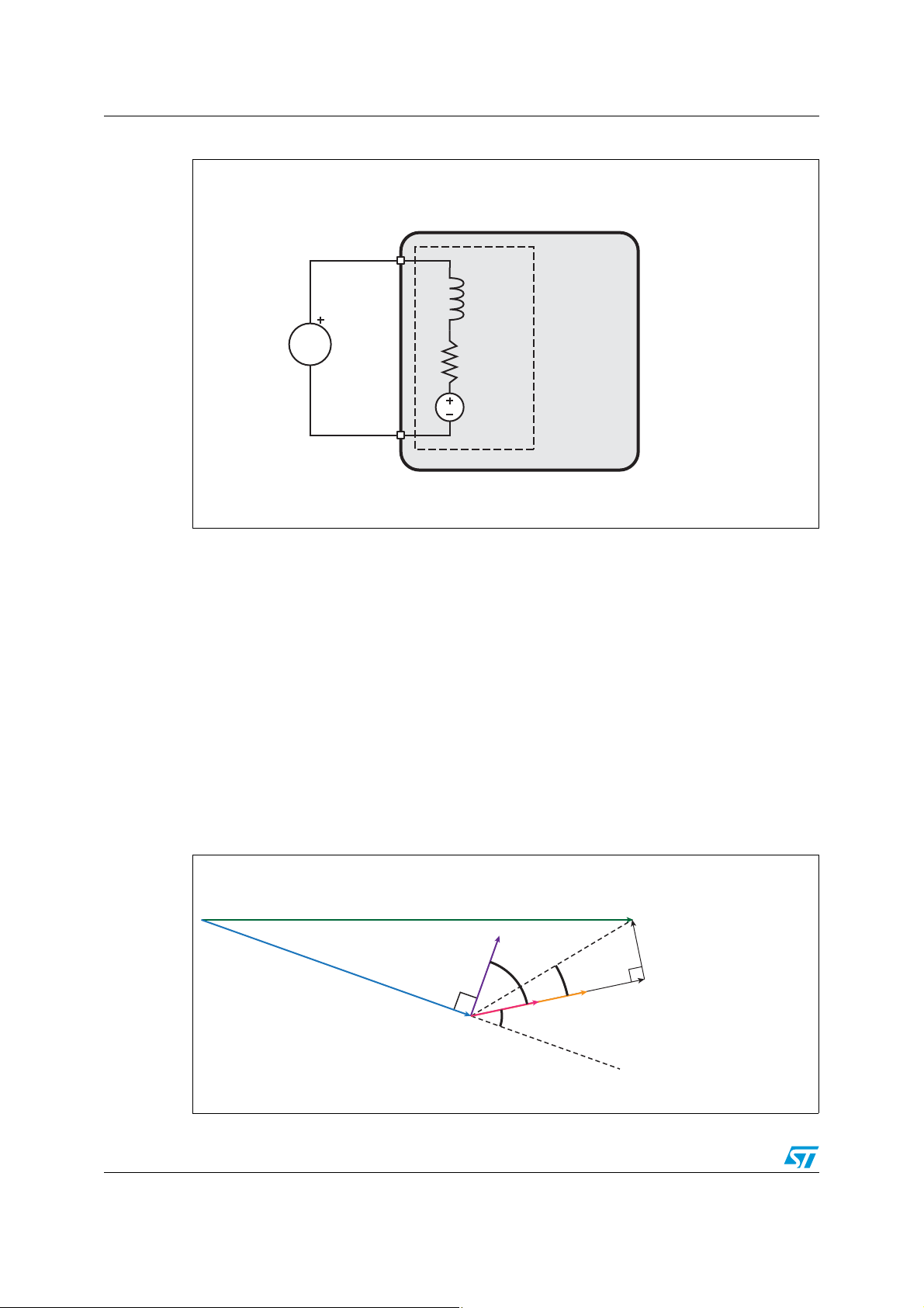
This result can be obtained through the analysis of the stepper motor electrical model.
Equation 1, extracted from the model in Figure 1, shows how the current of a generic motor
phase is related to:
● Phase voltage V
Back electromotive force (BEMF)
●
● Phase resistance (R
PH
) and inductance (Lm).
m
The back electromotive force is typically a sinusoidal voltage with frequency and amplitude
proportional to motor rotation speed. The BEMF frequency (f
rotation speed expressed in steps per second (f
); this frequency is exactly the same as
STEP
) is equal to one quarter of the
el
the hypothetical current sinewave that should be applied to the motor phase in order to
make the motor turn at f
frequency through a linear coefficient k
step rate. The BEMF amplitude is proportional to step
STEP
: this parameter depends on motor characteristics
e
and structure (rotor material, coil turns, etc.).
Doc ID 023491 Rev 1 5/28
Page 6
Voltage mode driving AN4144
VPH(t)
BEMF(fel, t)
L
m
R
m
Stepper motor
Motor phase
AM12849v1
iPHt()
V
PH
t() BEMF felt,()+
R
m
i2πfelLm⋅+
----------------------------------------------------------=
α
β
δ
V
PH
I
PH
Φ
STA
Φ
ROT
BEMF
Rm · I
PH
δ = arctan(2πf
el
· Lm/Rm)
2
πf
el
· Lm · I
PH
AM12850v1
Figure 1. Motor phase electrical model
Equation 1
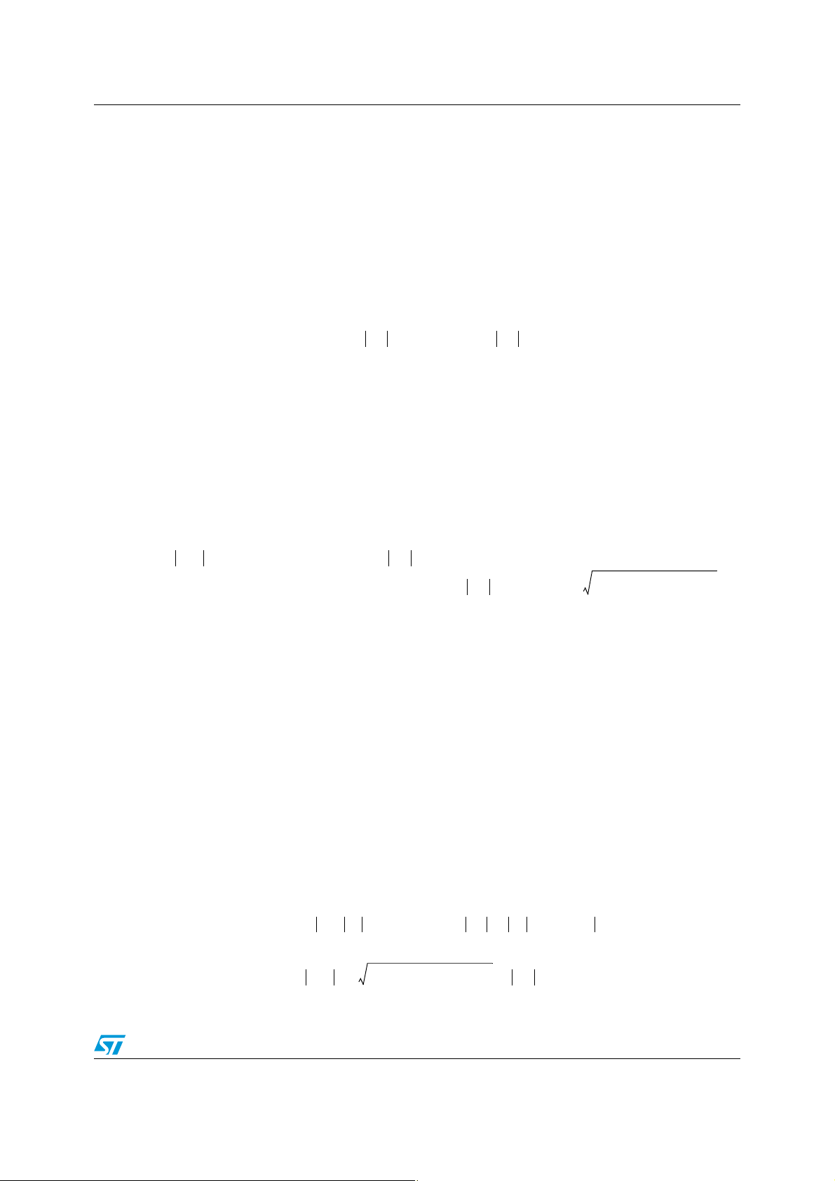
Considering all the currents and voltages of the electrical model as sinusoidal, Equation 1
can be written as a vector equation (Equation 2). The resulting vector system, which is
shown in Figure 2, adds a new variable to the current vs. voltage relationship: the load angle
β which is the angle between stator and rotor magnetic field vectors. The load angle is in
direct relation with the angle α lying between the phase current and BEMF phasors, as
shown in Equation 3.
The torque (Tq) applied to the motor shaft is proportional to both the phase current and the
sine of the load angle, as shown by Equation 4, where the k
constant which is equal to the k
constant, but expressed in Nm/A instead of V/Hz.
e
parameter is the motor torque
t
Figure 2. Phasor representation of motor phase equation
6/28 Doc ID 023491 Rev 1
Page 7
AN4144 Voltage mode driving
IPHfel()
V
PHfel
()BEMF fel()+
R
m
i2πfelLm⋅+
-------------------------------------------------------=
α
π
2
-- - β–=
T
q
KtI
PH
α()cos KtI
PH
π
2
-- - β–
⎝⎠
⎛⎞
cos⋅⋅=⋅⋅=
KtNm/A[]KeV/Hz[]=
V
PH
2
R
m
2
2πfel()2L
m
2
⋅+()I
PH
2
kefel⋅()
2
+⋅=
2 πα– arc 2πfelLm/R
m
⋅()tan–()I
PH
Kefel⋅()R
m
2
2πfel()2Lm⋅
2
+⋅⋅ ⋅cos–
VPH Rmi2πfelLm⋅+ IPH⋅ V
BEMFfel
()+≤
V
PH
R
m
2
2πfel()2L
m
2
⋅+ IPH⋅ K
efel
()⋅+=
Equation 2
Equation 3
Equation 4
Starting from Equation 2, it is possible to obtain the voltage amplitude which, when applied
to the motor phase, makes the amplitude of phase current constant. The basic principle of
Voltage mode control is based on this relationship. The resulting formula (Equation 5) shows
how the voltage amplitude is a complex function of phase current, motor parameters and
other factors.
Equation 5
Resolving this equation, to obtain the phase voltage to be applied for various speeds, is very
complex and computationally onerous. In addition, the phase relationship between the
current and the BEMF phasors (α) is difficult to measure or evaluate for a specific
application.
The STMicroelectronics control method, starting from this complex model, implements an
effective driving strategy that overcomes these issues with the classic current mode control
method in most microstepping applications.
1.2 Back EMF compensation algorithm
In order to devise a simple but effective compensation method, consider the formulas in
Equation 6. In this manner, the dependence on the load angle (β) can be removed, obtaining
a formula which allows the evaluation of the V
I
current independent of the motor speed (or its equivalent fel).
PH
Equation 6
voltage that is able to produce a constant
PH
Doc ID 023491 Rev 1 7/28
Page 8
Voltage mode driving AN4144
V
PH _APPLIED
R
mIPH_TARGETKefel
for 2πfelRm/L
m
«⋅+⋅
2πf
elLmIPH_TARGET
⋅⋅ Kefel for 2πfelRm/L
m
«⋅+
⎩
⎨
⎧
=
R
mIPH_TARGET
⋅
Ω[] A[] V[]=⋅
4Rm/2πL⋅
m
step
cycle
-------------- -
Ω[]/H[]⋅
step
cycle
-------------- -
= Hz[]⋅
step/s=
Using this formula, a compensation algorithm that gives the phase voltage amplitude (VPH)
for a target phase current (I
) and motor speed (fel) is defined.
PH
The compensation algorithm of Equation 6 can be further simplified according to the
electrical frequency. Two different cases can be considered, when the motor speed is low
(2
πf
<< R/L) and when it is high (2πf
el
>> R/L).
el
Equation 7 shows how the formula can be approximated when these two cases are
considered.
Equation 7
The Voltage mode control implemented in STMicroelectronics’ products is based on the
simplified model described by Equation 7.
In particular, the following parameters are extracted and used to describe the compensation
curve:
● K
is the voltage applied to the motor phase at zero speed. It is the starting point of
val
the BEMF compensation curve
● Intersect speed is the motor speed that determines the switching from the low-speed
compensation factor (starting slope) to the high-speed one (final slope)
● Starting slope is the rate at which the phase voltage is increased in the low-speed
range (i.e. motor speed is less than intersect speed)
● Final slope is the rate at which the phase voltage is increased in the high-speed range
(i.e. motor speed is greater than intersect speed).
These parameters are listed inTab le 1 .
Table 1. BEMF compensation parameters
Parameter Description Formula Unit
Voltage applied to the
K
val
Intersect
speed
phase at zero speed in
order to obtain the
target current value.
Motor speed
discriminating the
compensation slope
that should be used.
8/28 Doc ID 023491 Rev 1
Page 9
AN4144 Voltage mode driving
Ke/4
V
Hz
-------
/
step
cycle
-------------- -
=
V[] s/step⋅
2π L
mIPH-TARGETKe
+⋅⋅()/4
V
Hz
-------
/
step
cycle
-------------- -
=
V[] s/step⋅
V
PH
V
BUS
t
ON
t
SW
-------- V
BUS
DutyCycle
PMW
⋅=⋅=
VPH/V
BUS
Speed
[step/s]
Intersect
speed
Kv al
Starting
slope
Final
slope
AM12859v1
Table 1. BEMF compensation parameters (continued)
Parameter Description Formula Unit
Compensation slope
Starting
slope
Final slope
used when motor
speed is lower than
intersect speed.
Compensation slope
used when motor
speed is higher than
intersect speed.
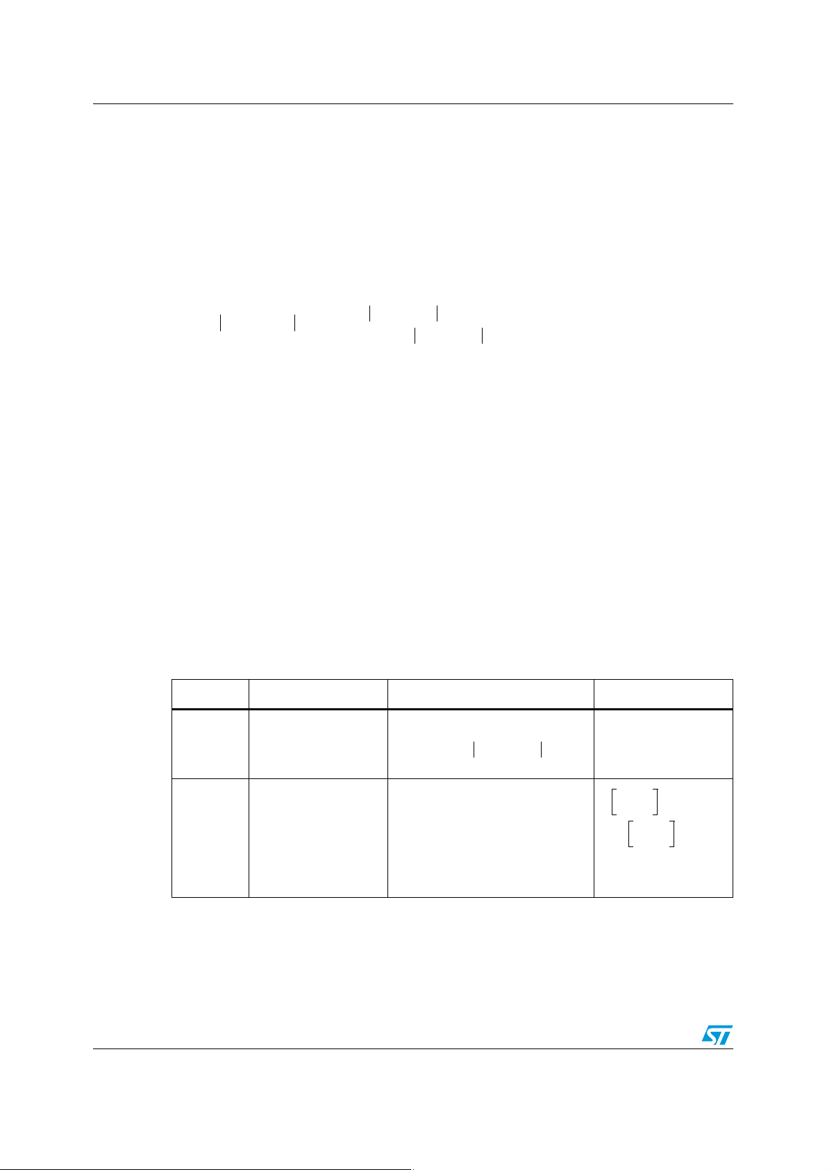
The control system generates the phase voltage using a PWM modulation. The outputs
switch between supply voltage V
and ground at a fixed frequency. The mean voltage of
BUS
the resulting square-wave is adjusted through its duty cycle (on time over square-wave
period ratio) according to the following formula:
Equation 8
The duty cycle ranges from 0% (the output is always forced to ground) to 100% (the output
is always forced to V
BUS
).
The BEMF compensation curve is implemented adjusting the PWM duty cycle, so all the
voltage values must be normalized to the supply voltage of the power stage (Figure 3).
Figure 3. BEMF compensation curve
Doc ID 023491 Rev 1 9/28
Page 10

Voltage mode driving AN4144
R
mIPH_TARGET/VBUS
⋅
Ω[] A[]/V[]=%⋅
4Rm/2πL
m
⋅
step
cycle
-------------- -
Ω[]/H[]⋅
step
cycle
-------------- -
= Hz[]⋅
step/s=
Ke/4()/V
BUS
V
Hz
-------
/
step
cycle
-------------- -
⎝⎠
⎛⎞
=/ V[]=% s/step⋅
2π L
mIPH-TARGETKe
+⋅⋅()/4()/V
BUS
V
Hz
-------
/
step
cycle
-------------- -
⎝⎠
⎛⎞
=/ V[]=% s/step⋅
1.6
Maximum current value according to bus voltage
Motor characteristics:
1.2
1.4
R
m
=
5
L
m
=
3
mH
k
e
=
0.03V/Hz
1
1.2
]
0.6
0.8
Current [
0.4
0
0.2
052
002051
00
10
5
0
Speed [step/s]
36
V
24 V 15 V 12 V
Ω
AM12860v1
Table 2. BEMF compensation parameters normalized to the supply voltage (V
Parameter Formula Unit
K
val
Intersect speed
Starting slope
Final slope
The supply voltage of the systems limits the maximum phase current which is a function of
the motor speed. If the phase voltage which is needed to obtain the target current is greater
than the supply voltage, the phase current cannot reach the expected value (Figure 4).
BUS
)
Figure 4. Maximum output current limitation example
A
10/28 Doc ID 023491 Rev 1
Page 11

AN4144 Voltage mode driving
V
PH
V
BUS
DutyCycle
PMW
⋅=
6
"53
6
2%'
$%6)#%
!$#).
!$#
!-V
V
PH
V
BUS
ε⋅()DutyCycle
PMWKε
⋅()V
BUS
DutyCycle
PMW
⋅=⋅=
1.3 Motor supply voltage compensation
The power stage generates the voltage sinewaves using a PWM modulation method, so the
average output voltage value is proportional to the motor supply voltage (V
bridge duty cycle (see Equation 9). Therefore, perturbations on this voltage cause errors on
the output voltage and then on the phase currents.
Equation 9
In most industrial applications, the supply voltage is not well regulated and it may undergo
significant voltage fluctuations, due to various factors, e.g. variations of load conditions.
The Voltage mode algorithm implemented in STMicroelectronics devices provides a
compensation system that increases the supply voltage rejection of PWM modulator.
The supply voltage is constantly monitored through a voltage divider and an integrated
analog-to-digital converter and the power stage duty cycle is changed in order to
compensate for its variations.
Figure 5. Supply voltage compensation system
) and power
BUS
The voltage divider should be sized in order to obtain V
/2 at the ADC input when the
REF
supply voltage is at its nominal value. When the supply voltage is perturbed, the same
distortion is proportionally applied to the ADC input and the nominal duty cycle is multiplied
by a compensation coefficient k
, as shown in Equation 10.
ε
Equation 10
where k
=1/ε.
ε
Doc ID 023491 Rev 1 11/28
Page 12

Voltage mode driving AN4144
RmT() R
mT0,
RT() R
mT0,
R
mT0,
δ TT
0
–()⋅⋅+=Δ+=
In any case, the compensation system is limited by the actual supply voltage: if the
compensated duty cycle (DutyCycle
PWM
⋅ k
) is greater than 100%, the supply voltage is
e
not large enough to obtain the target current (maximum output current limit has been
reached) and the compensation algorithm fails.
1.4 Compensation of thermal drift of the phase resistance
During operation, the motor dissipates energy and increases its temperature, therefore the
phase resistance. The relationship between phase resistance and temperature is shown in
Equation 11: the change in the phase resistance is proportional to the temperature variation,
its nominal value (phase resistance at room temperature T
(
σ) of the material composing the coil.
Equation 11
As described in previous paragraphs, the voltage-to-current relation depends on different
motor parameters, including phase resistance (R
in Equation 1). In particular, a higher
m
phase resistance reduces the load current at the same applied voltage.
The duty cycle of the PWM output is multiplied by a scalar factor in order to compensate for
the resistance variation.
) and the temperature coefficient
0
12/28 Doc ID 023491 Rev 1
Page 13

AN4144 Tuning of the BEMF compensation parameters
2 Tuning of the BEMF compensation parameters
This paragraph describes how the BEMF compensation parameters can be tuned in order to
obtain the best results. Setting the correct compensation parameters is fundamental to
Voltage mode algorithm performance.
The tuning sequence can be divided into the following steps:
● Collecting the characteristics of the application and motor (Section 2.1)
● Obtaining a preliminary set of parameters (Section 2.2)
● Tuning the parameters in order to obtain the needed results (Section 2.3).
2.1 Collecting the application characteristics
The compensation system is based on the electrical model of the stepper motor, so its setup
is strongly dependent on the motor characteristics.
The required information is:
● Resistance of the motor phase (R
● Inductance of the motor phase (L
● Electrical constant of the motor (k
The R
and Lm values are usually reported on the motor datasheet. They can also be
m
measured with common measuring instruments.
)
m
)
m
).
e
If the user has an RLC meter, they can connect it to one of the motor phases and measure
the series R and L at 100 Hz (make sure the motor does not move). The resulting values are
considered to be R
If they do not have an RLC meter, the R
and Lm.
m
can be measured using a bench multimeter
m
applied to one of the phases.
To measure the L
● Connect a DC voltage at one motor phase and apply the voltage and current probes of
, use the following procedure:
m
the oscilloscope, as shown in the Figure 6 A
● Increase the voltage up to the value where the current equals the nominal value
● For a better measurement, lock the rotor position
● Unplug one terminal of the voltage source cable without switching it off and disable (or
set to the max.) the current limitation
● Connect the voltage source rapidly and monitor, on the scope, the voltage and current
waveform
● The measurement is good if the voltage trace is similar to a step and the current
increases exponentially (Figure 6 B)
● Measure the time for the current waveform to rise up to 63% of the nominal value
(Figure 6 B)
● This time is equal to the L
m/Rm
ratio.
Doc ID 023491 Rev 1 13/28
Page 14

Tuning of the BEMF compensation parameters AN4144
Phase A
Phase B
V
I
ph
I
ph
V
ph
V
ph
(A) (B)
63%
T = L
ph/Rph
AM12862v1
Figure 6. Phase inductance measurement
The k
is the coefficient that relates the motor speed to the BEMF amplitude. This value is
e
not usually present on stepper motor datasheets, but it can be easily measured by means of
an oscilloscope:
● Connect one of the motor phases to an oscilloscope channel
● Set the oscilloscope to the trigger value on the rising or falling edge of the channel and
set the threshold value close to zero (few mV above or below zero)
● Turn the motor shaft. This can be done by hand or by means of another motor. The
most important thing is to obtain a rotation speed as constant as possible
● Set oscilloscope time and voltage scales in order to display a sinewave during the
motor rotation.
If the rotor is turned by hand, the operations should be repeated until a good sinewave is
obtained. A good sinewave keeps its amplitude constant for at least 2 or 3 cycles (Figure 7
and Figure 8). This operation might require several attempts.
● Measure the peak voltage to frequency ratio of the sinewave. The resulting value is the
motor electric constant expressed in V/Hz.
14/28 Doc ID 023491 Rev 1
Page 15

AN4144 Tuning of the BEMF compensation parameters
R
mIPH_TARGET/VBUS
28⋅⋅
4Rm/2πL
m
⋅()226t
tick
⋅⋅
Ke/4()/V
BUS
()216⋅
2π L
mIPH-TARGETKe
+⋅⋅()/4()/V
BUS
()216⋅
Figure 7. Bad k
measurement waveform Figure 8. Good ke measurement waveform
e
2.2 First dimensioning
A preliminary set of parameters can be obtained starting from the simplified model of the
stepper motor described in Section 1.1.
Starting from the formulas listed in Ta bl e 2 of Section 1.2, it is possible to define the BEMF
compensation register values as shown in the following table:
Table 3. BEMF compensation register values according to application parameters
Parameter Register name Register value
KVAL_HOLD,
K
val
Intersect speed INT_SPEED
Starting slope ST_SLP
Final slope
KVAL_ACC,
KVAL_DEC, KVAL_RUN
FN_SLP_ACC,
FN_SLP_DEC
where t
= 250 ns
tick
The resulting values are not the optimal compensation values because they are obtained
starting from a simplified model of the motor. They can be used as a starting point for further
optimization of the control system.
The same result can be easily obtained using the BEMF compensation tool which is
integrated into the L6470 evaluation software.
Doc ID 023491 Rev 1 15/28
Page 16

Tuning of the BEMF compensation parameters AN4144
6
/546"53
-INIMUMOUTPUT
VOLTAGE
#OMPENSATION
CURVEFOR)
25."
#OMPENSATION
CURVEFOR)
25.!
4HE)
25."
CURVE
CANNOTBEPERFORMED
3PEED
;STEPS=
!-V
2.2.1 Holding, acceleration, deceleration and running currents
The BEMF compensation system allows different current values according to motion status.
The different current values are set through a specific set of registers, as shown in Ta b le 4 .
Table 4. Motor status and BEMF compensation registers relationship
Motor status Registers
Hold (motor stopped) KVAL_HOLD
Acceleration
Deceleration
Constant speed
KVAL_ACC, INT_SPEED, ST_SLP,
FN_SLP_ACC
KVAL_DEC, INT_SPEED, ST_SLP,
FN_SLP_DEC
KVAL_RUN, INT_SPEED, ST_SLP,
FN_SLP_ACC
The holding current generates the magnetic field that keeps the motor in position after the
motion is completed. Its value is usually lower than the others because it is not necessary to
face the friction and the inertial component of the load torque. In these conditions the BEMF
value is zero, so no compensation is needed and the only parameter defining the current is
KVAL_HOLD.
During the acceleration phase the current is set through the KVAL_ACC, INT_SPEED,
ST_SLP and FN_SLP_ACC parameters.
The constant speed current setup shares most of the parameters with the acceleration
setup (INT_SPEED, ST_SLP and FN_SLP_ACC), so the two currents are closely related.
The BEMF compensation curve for the acceleration phase (INT_SPEED, ST_SLP and
FN_SLP_ACC parameters) defines the minimum output voltage at each speed limiting the
minimum constant speed current (Figure 9).
Figure 9. Running current limit
16/28 Doc ID 023491 Rev 1
Page 17

AN4144 Tuning of the BEMF compensation parameters
2.2.2 Compensation register values out of range
In some cases the values obtained using the formulas listed in Ta b le 3 may be out of the
range of the respective registers.
If one of the K
registers exceeds the maximum limit of 255 (corresponding to a PWM
VAL
duty cycle close to 100%), the motor supply voltage is not large enough to force the target
current into the phase resistance. In this case, the application parameters (supply voltage,
target current and motor characteristics) are not consistent and they should be changed.
Example 1
V
=12 V; Rm=9 Ω; I
BUS
K
= R
VAL
m
⋅ |I
PH_TARGET
PH TARGET
| / V
BUS
= 2 A
8
⋅ 2
= 384 > max. KVAL value (255)
Target current is not achievable.
If the intersect speed exceeds the maximum value, the resistive component of the motor
phase impedance dominates the inductive component, so the increase of the impedance
with speed can be considered negligible and its compensation is unnecessary. In this case,
the maximum intersect speed value may be used and during the fine tuning phase particular
attention should be paid to the intersect speed region.
Example 2
L
= 4 mH; Rm =10 Ω
m
4
⋅ R
=10000 steps/s -> maximum value should be used.
m/Lm
If one or more of the compensation slope parameters (ST_SLP, FN_SLP_ACC and
FN_SLP_DEC) exceeds the maximum value, the motor supply voltage is not enough to
counteract the BEMF voltage increase.
The maximum compensation rate is 0.04% of the bus voltage at step/s. Considering a
starting K
value equal to zero, this compensation rate reaches 100% of the bus voltage
VAL
at a rotation speed of only 250 step/s.
So a high compensation value does not correspond to any real application. The application
parameters (supply voltage, target current and motor characteristics) are not consistent and
they should be changed.
2.3 Fine tuning
In some cases, the results obtained after the first dimensioning of the BEMF parameters
(Section 2.2) do not fit with the performance required by the application. In these cases the
optimal compensation can be obtained by fine tuning the system.
Performing these adjustments requires a current probe that is able to measure the phase
currents over the entire operating range of the application.
The following procedure describes how to tune the acceleration parameters of the BEMF
compensation system (KVAL_ACC, INT_SPEED, ST_SLP and FN_SLP_ACC). Replacing
the KVAL_ACC and FN_SLP_ACC values with the respective deceleration parameters
(KVAL_DEC and FN_SLP_DEC), the same procedure can be used to tune the BEMF
compensation in the deceleration phase. Intersect speed and starting slope parameters are
shared by both the acceleration and deceleration compensation setups (Section 2.2.1), so
their tuning should be performed one time only.
Doc ID 023491 Rev 1 17/28
Page 18

Tuning of the BEMF compensation parameters AN4144
2.3.1 Step 1: verify the phase current during the speed sweep
The most important step in the fine tuning of the BEMF compensation system is the analysis
of the result obtained through the first dimensioning procedure.
This check can be performed monitoring the phase current of the motor during a slow
acceleration (e.g. 200 - 400 step/s
If the amplitude of the phase current is constant during the entire acceleration, the BEMF is
well compensated. Otherwise, the BEMF compensation parameters should be tuned.
Figure 10 shows an example of sub-optimal BEMF compensation obtained using the first
dimensioning formulas (target peak current equal to 1 A).
Figure 10. Speed sweep with first dimensioning parameters
2
) up to the maximum speed of the application.
2.3.2 Step 2: adjust the starting amplitude (KVAL)
The first value which must be adjusted is the starting amplitude (KVAL). The value is tuned
using the following method:
1. Copy the first dimensioning value of the parameter into the KVAL_HOLD register.
2. Set the electrical position register EL_POS to one of the full step position values
(0x000, 0x080, 0x100 or 0x180).
3. Turn on the device outputs sending a HardStop command to the IC (only one phase of
the motor is driven according to the electrical position value as listed in Ta b l e 5 , the
other outputs are forced to ground through the low-side MOSFETs).
4. Measure the driving current and adjust the KVAL value in order to obtain the required
peak current.
18/28 Doc ID 023491 Rev 1
Page 19

AN4144 Tuning of the BEMF compensation parameters
Table 5. Output current according to the electrical position
Electrical position Output current
0x000
0x080
0x100
0x180
OUTB1 source, OUTB2 sink.
OUTA1 and OUTA2 shorted to ground.
OUTA1 source, OUTA2 sink
OUTB1 and OUTB2 shorted to ground.
OUTB2 source, OUTB1 sink
OUTA1 and OUTA2 shorted to ground.
OUTA2 source, OUTA1 sink
OUTB1 and OUTB2 shorted to ground.
2.3.3 Step 3: adjust the intersect speed value
The most important parameter in the BEMF compensation algorithm is the intersect speed.
Its optimal value can be determined by performing a speed sweep (i.e. a slow acceleration
as described in Section 2.3.1) setting the final slope value equal to the starting slope value
which has been obtained during the first dimensioning.
The resulting phase current is almost constant in the first part of the motion and it decreases
at higher speed (a motor stall may occur before the maximum speed is reached). The
intersect speed value is the motor speed at which the phase current begins decreasing; e.g.
in Figure 11 the optimal intersect speed value is about 138.9 step/s.
Figure 11. Evaluation of the optimal intersect speed value
2.3.4 Step 4: adjust the starting and final slopes
After setting the new value for the intersect speed, the starting and final slopes must be
adjusted. It is recommended to change one of the two values at a time; changing both the
starting and final slopes simultaneously may make it more difficult to find the optimal
combination. As for the intersect speed, the correct values can be obtained by measuring
the phase current during a series of speed sweeps.
Doc ID 023491 Rev 1 19/28
Page 20

Tuning of the BEMF compensation parameters AN4144
To tune the starting slope value, the initial part of the acceleration (from zero to the intersect
speed) must be considered (Figure 12). If the current amplitude increases, the starting
slope value must be reduced, otherwise it must be increased.
The same operation must be done for the evaluation of the final slope value, but the final
part of the acceleration must be considered (Figure 13).
Figure 12. Tuned starting slope value
Figure 13. Tuned final slope value
2.3.5 Step 5: final check
When all the values have been tuned and the optimal compensation is obtained, a final
check should be done. Performing a speed sweep the measured current amplitude must be
almost constant. According to the oscilloscope characteristics, some artifacts (Figure 14)
may be displayed when long time acquisitions are performed.
20/28 Doc ID 023491 Rev 1
Page 21

AN4144 Tuning of the BEMF compensation parameters
Figure 14. Final check acquisition showing artifacts
In order to avoid mistaking artifacts for real compensation errors, the following suggestions
should be considered:
● If present, use the ZOOM function of the oscilloscope to magnify the critical areas
(Figure 15)
● Split the acceleration into more parts.
Figure 15. Magnified acquisition verifies the presence of artifacts
Doc ID 023491 Rev 1 21/28
Page 22

Supply voltage compensation guidelines AN4144
3 Supply voltage compensation guidelines
The effectiveness of the compensation is strongly dependent on the actual duty cycle value
because the system is not able to overcome the maximum duty cycle of 100%. When the
variations of the application supply voltage make the use of the compensation system
essential, the maximum target current is limited by the lower voltage value which is expected
from the power supply output.
For this reason, the application setup, i.e. motor characteristics and phase currents, should
be chosen considering the minimum expected supply voltage.
For example, suppose 85% of the 24 V bus is needed in order to reach the target current at
1000 step/s. If the bus voltage is reduced by 20% (i.e. the actual voltage is 24 V
19.2 V), the compensation system increases the duty-cycle by a factor of 1/0.8 = 1.25. In
this case the resulting duty cycle is 106.25%, which is greater than the maximum available
value (100%).
Example 3
V
V
BUS
BUS
= V
BUS,nom
= 0.8 ⋅ V
= 24 V -> DutyCycle
BUS,nom
= 19.2 V -> DutyCycle
@1000 step/s = 85%
PWM
@1000 step/s = 85% / 0.8 =106.25%
PWM
⋅ 0.8 =
22/28 Doc ID 023491 Rev 1
Page 23

AN4144 Thermal drift compensation guidelines
4 Thermal drift compensation guidelines
The compensation of the thermal drift of the phase resistance is not automatically
performed by STMicroelectronics devices, but a compensation factor (KTHERM) is made
available through a dedicated register.
The thermal compensation factor (KTHERM) is a scalar value between 1 (no compensation)
and 1.5, which is applied to the PWM value obtained by the other compensation systems
(BEMF compensation and supply voltage compensation).
As shown in Equation 11 of Section 1.4, the thermal drift of the resistance is directly
proportional to the nominal resistance value (R
reason the thermal drift compensation becomes more important when the driven motor has
a high phase resistance value.
A suggested implementation of the thermal drift compensation is based upon the phase
current measurement during the non-operative period of the motor (if present).
The proposed method requires an initial calibration of the system (performed when the
motor is cold) and described by the following sequence:
1. The motor is stopped in a specific electrical position.
2. The overcurrent or stall detection threshold is set to a calibration value (I
3. The output voltage is increased at a low rate through the KVAL_HOLD parameter.
4. When the calibration current is reached, the respective KVAL_HOLD value must be
stored (KCAL) in the MCU memory.
) and the temperature variation. For this
m,T0
).
cal
Since the KCAL value is related to the design parameters only, this calibration can also be
performed during the design of the application. However, because of the variation of the
application characteristics (bus voltage, motor phase resistance, etc.) and the device
circuitry (current sensing), it would be useful to perform the calibration sequence on each
system instead of defining a single KCAL value during the application design.
When a significant change of the motor temperature is expected, the following
compensation sequence can be performed:
1. The motor is stopped in the same electrical position used during the calibration.
2. The overcurrent or stall detection threshold is set to a calibration value (I
cal
).
3. The KVAL_HOLD value is set to KCAL.
4. The compensation coefficient (K_THERM) is increased or decreased in order to reach
the calibration current using the overcurrent/stall information provided by the device.
Doc ID 023491 Rev 1 23/28
Page 24

Stepper motor resonances AN4144
S
T
E
P
T
POSITION
!-V
5 Stepper motor resonances
The stepper motors, as in all complex mechanical systems, have one or more resonance
points. These resonances are strictly related to the motion performed by the stepper motors:
at each step (or microstep) the rotor approaches the new position and it oscillates around
this position before stopping (Figure 16). When the step rate matches the oscillation
frequency, the mechanical resonance is stimulated which results in a jittering motion. In
some cases the vibration can be strong enough to cause a step loss or motor stall.
Figure 16. Position ripple caused by the step change
The position, and the strength of these resonance points, depends on the relationship
between motor characteristics (in particular the inertia and the stiffness of the rotor) and
mechanical load connected to the shaft.
5.1 The effects of the resonances on Voltage mode driving
The vibrations caused by the motor resonances distort the back electromotive force making
the model described in Section 1.1 no longer valid. In fact, if the back EMF is not sinusoidal,
applying a sinusoidal voltage to the motor phase results in a distorted current (Figure 17).
The distortion of the phase current may amplify the resonances and cause a motor stall
(Figure 18).
24/28 Doc ID 023491 Rev 1
Page 25

AN4144 Stepper motor resonances
Figure 17. Phase current distortion
Figure 18. Motor stall caused by resonances
3FTPOBODFDPOEJUJPO
DVSSFOUEJTUPSUFE
4UBMMDPOEJUJPO
OP#&.'OPDVSSFOUEJTUPSUJPO
5.2 Facing resonances
Facing resonances is a critical issue in the development of a stepper motor application. This
section lists the most common solutions to reduce or avoid resonance effects.
5.2.1 Damping resonances using the mechanical load
The worst condition for stepper motor driving is when the shaft is unloaded. When the shaft
remains unloaded, all the energy provided to the motor is dissipated by the rotor itself
exciting its resonance points.
!-V
Doc ID 023491 Rev 1 25/28
Page 26

Stepper motor resonances AN4144
Even a small load can dampen the rotor oscillations enough to make the motion smoother.
Moreover, the mechanical load adds inertia to the system shifting the resonance points. The
stepper motor mounting can also influence the resonance frequencies.
5.2.2 Reducing motor current
As previously described, the resonances are caused by the rotor oscillations during a step
change. The amplitude of these oscillations is proportional to the intensity of the stimulating
magnetic field, i.e. the current value. Reducing the phase current to the minimum required
reduces the strength of the resonances.
Many times the resonance points of the stepper motor are represented as a lack of torque
on the speed-torque curve. This representation may cause misunderstandings with this
issue. The reduced torque is not the root cause of the problem (resonance), but it is the
consequence of it. Therefore, increasing the phase current in order to compensate for the
torque reduction is usually not a solution.
5.2.3 Skipping the resonance points increasing the acceleration
The most common method to avoid resonance points is to quickly accelerate past their
positions. Working within the range of the system resonances is never recommended even
for a short period of time.
High acceleration values allow the motor to pass through the resonance points faster,
reducing the negative effects.
26/28 Doc ID 023491 Rev 1
Page 27

AN4144 Revision history
6 Revision history
Table 6. Document revision history
Date Revision Changes
26-Jul-2012 1 Initial release.
Doc ID 023491 Rev 1 27/28
Page 28

AN4144
Please Read Carefully:
Information in this document is provided solely in connection with ST products. STMicroelectronics NV and its subsidiaries (“ST”) reserve the
right to make changes, corrections, modifications or improvements, to this document, and the products and services described herein at any
time, without notice.
All ST products are sold pursuant to ST’s terms and conditions of sale.
Purchasers are solely responsible for the choice, selection and use of the ST products and services described herein, and ST assumes no
liability whatsoever relating to the choice, selection or use of the ST products and services described herein.
No license, express or implied, by estoppel or otherwise, to any intellectual property rights is granted under this document. If any part of this
document refers to any third party products or services it shall not be deemed a license grant by ST for the use of such third party products
or services, or any intellectual property contained therein or considered as a warranty covering the use in any manner whatsoever of such
third party products or services or any intellectual property contained therein.
UNLESS OTHERWISE SET FORTH IN ST’S TERMS AND CONDITIONS OF SALE ST DISCLAIMS ANY EXPRESS OR IMPLIED
WARRANTY WITH RESPECT TO THE USE AND/OR SALE OF ST PRODUCTS INCLUDING WITHOUT LIMITATION IMPLIED
WARRANTIES OF MERCHANTABILITY, FITNESS FOR A PARTICULAR PURPOSE (AND THEIR EQUIVALENTS UNDER THE LAWS
OF ANY JURISDICTION), OR INFRINGEMENT OF ANY PATENT, COPYRIGHT OR OTHER INTELLECTUAL PROPERTY RIGHT.
UNLESS EXPRESSLY APPROVED IN WRITING BY TWO AUTHORIZED ST REPRESENTATIVES, ST PRODUCTS ARE NOT
RECOMMENDED, AUTHORIZED OR WARRANTED FOR USE IN MILITARY, AIR CRAFT, SPACE, LIFE SAVING, OR LIFE SUSTAINING
APPLICATIONS, NOR IN PRODUCTS OR SYSTEMS WHERE FAILURE OR MALFUNCTION MAY RESULT IN PERSONAL INJURY,
DEATH, OR SEVERE PROPERTY OR ENVIRONMENTAL DAMAGE. ST PRODUCTS WHICH ARE NOT SPECIFIED AS "AUTOMOTIVE
GRADE" MAY ONLY BE USED IN AUTOMOTIVE APPLICATIONS AT USER’S OWN RISK.
Resale of ST products with provisions different from the statements and/or technical features set forth in this document shall immediately void
any warranty granted by ST for the ST product or service described herein and shall not create or extend in any manner whatsoever, any
liability of ST.
ST and the ST logo are trademarks or registered trademarks of ST in various countries.
Information in this document supersedes and replaces all information previously supplied.
The ST logo is a registered trademark of STMicroelectronics. All other names are the property of their respective owners.
© 2012 STMicroelectronics - All rights reserved
STMicroelectronics group of companies
Australia - Belgium - Brazil - Canada - China - Czech Republic - Finland - France - Germany - Hong Kong - India - Israel - Italy - Japan -
Malaysia - Malta - Morocco - Philippines - Singapore - Spain - Sweden - Switzerland - United Kingdom - United States of America
www.st.com
28/28 Doc ID 023491 Rev 1
 Loading...