


AN4133
Application note
Using the SPIRIT1 transceiver under ARIB STD-T108 in the
920 MHz band
By Placido De Vita
Introduction
SPIRIT1 is a very low power RF transceiver, intended for RF wireless applications in the
sub-1 GHz band. It is designed to operate both in the license-free ISM and SRD frequency
bands at 169, 315, 433, 868, 915 and 920 MHz.
The Japanese Association of Radio Industries and Businesses (ARIB) was established in
response to several trends such as the growing internationalization of telecommunications,
the convergence of telecommunications and broadcasting and the need for promotion of
radio-related industries. The ARIB organism defines the basic technical requirements for
standard specifications of radio equipment.
This application note outlines the expected performance when using the Spirit1 under ARIB
STD-T108 (see References on page 33) in the 920 MHz band. For details on the regulatory
limits in the 920 MHz frequency band, please refer to the ARIB STD-T108 regulation in
References on page 33.
These can be downloaded from www.arib.or.jp/english/index.html.
July 2012 Doc ID 023362 Rev 1 1/35
www.st.com

Contents AN4133
Contents
1 An overview of ARIB STD-T108 regulation . . . . . . . . . . . . . . . . . . . . . . . 5
1.1 Convenience radio stations . . . . . . . . . . . . . . . . . . . . . . . . . . . . . . . . . . . . 5
1.2 Low-power radio stations . . . . . . . . . . . . . . . . . . . . . . . . . . . . . . . . . . . . . . 6
2 Application circuit . . . . . . . . . . . . . . . . . . . . . . . . . . . . . . . . . . . . . . . . . . . 8
3 Transmitter . . . . . . . . . . . . . . . . . . . . . . . . . . . . . . . . . . . . . . . . . . . . . . . . 11
3.1 Adjacent channel leakage power . . . . . . . . . . . . . . . . . . . . . . . . . . . . . . . 11
4 Permissible values for unwanted emission intensity . . . . . . . . . . . . . 20
5 Receiver . . . . . . . . . . . . . . . . . . . . . . . . . . . . . . . . . . . . . . . . . . . . . . . . . . 29
5.1 Limit on secondary radiated emission . . . . . . . . . . . . . . . . . . . . . . . . . . . 29
6 References . . . . . . . . . . . . . . . . . . . . . . . . . . . . . . . . . . . . . . . . . . . . . . . . 33
7 Revision history . . . . . . . . . . . . . . . . . . . . . . . . . . . . . . . . . . . . . . . . . . . 34
2/35 Doc ID 023362 Rev 1

AN4133 List of tables
List of tables
Table 1. Permissible values for unwanted emission intensity. . . . . . . . . . . . . . . . . . . . . . . . . . . . . . . 5
Table 2. Limit on secondary radiated emissions, etc. at receiver . . . . . . . . . . . . . . . . . . . . . . . . . . . . 6
Table 3. Permissible values for unwanted emission intensity. . . . . . . . . . . . . . . . . . . . . . . . . . . . . . . 7
Table 4. Limit on secondary radiated emissions, etc. at receiver . . . . . . . . . . . . . . . . . . . . . . . . . . . . 7
Table 5. Document revision history . . . . . . . . . . . . . . . . . . . . . . . . . . . . . . . . . . . . . . . . . . . . . . . . . 34
Doc ID 023362 Rev 1 3/35

List of figures AN4133
List of figures
Figure 1. SPIRIT1 application daughterboard . . . . . . . . . . . . . . . . . . . . . . . . . . . . . . . . . . . . . . . . . . . 8
Figure 2. SPIRIT1 application daughterboard plugged into the motherboard . . . . . . . . . . . . . . . . . . . 9
Figure 3. Daughterboard schematic. . . . . . . . . . . . . . . . . . . . . . . . . . . . . . . . . . . . . . . . . . . . . . . . . . 10
Figure 4. Convenience radio station channel mask of a radio channel whose frequency is
from 920.5 MHz to 922.3 MHz . . . . . . . . . . . . . . . . . . . . . . . . . . . . . . . . . . . . . . . . . . . . . . 13
Figure 5. Convenience radio station channel mask of a radio channel at 922 MHz . . . . . . . . . . . . . 13
Figure 6. Convenience radio station channel mask of a radio channel whose frequency is
from 922.3 MHz to 923.5 MHz . . . . . . . . . . . . . . . . . . . . . . . . . . . . . . . . . . . . . . . . . . . . . . 14
Figure 7. Convenience radio station channel mask of a radio channel at 923 MHz . . . . . . . . . . . . . 14
Figure 8. Low-power radio station channel mask of a radio channel whose frequency is
from 915.9 MHz to 916.9 MHz . . . . . . . . . . . . . . . . . . . . . . . . . . . . . . . . . . . . . . . . . . . . . . 15
Figure 9. Low-power radio station channel mask of a radio channel at 916.5 MHz. . . . . . . . . . . . . . 15
Figure 10. Low-power radio station channel mask of a radio channel whose frequency is
from 920.5 MHz to 922.3 MHz . . . . . . . . . . . . . . . . . . . . . . . . . . . . . . . . . . . . . . . . . . . . . . 16
Figure 11. Low-power radio station channel mask of a radio channel at 921.5 MHz . . . . . . . . . . . . . 16
Figure 12. Low-power radio station channel mask of a radio channel whose frequency is
from 922.3 MHz to 928.1 MHz (antenna power is 1 mW or less)l . . . . . . . . . . . . . . . . . . . 17
Figure 13. Low-power radio station channel mask of a radio channel at 928 MHz . . . . . . . . . . . . . . . 17
Figure 14. Low-power radio station channel mask of a radio channel whose frequency is
from 922.3 MHz to 928.1 MHz (antenna power is more than 1 mW and 20 mW or less). . 18
Figure 15. Low-power radio station channel mask of a radio channel at 925 MHz . . . . . . . . . . . . . . . 18
Figure 16. Low-power radio station channel mask of a radio channel whose frequency is
from 928.1 MHz to 929.7 MHz . . . . . . . . . . . . . . . . . . . . . . . . . . . . . . . . . . . . . . . . . . . . . . 19
Figure 17. Low-power radio station channel mask of a radio channel at 929 MHz . . . . . . . . . . . . . . . 19
Figure 18. Convenience radio station emission in the 10 - 710 MHz bandwidth . . . . . . . . . . . . . . . . . 20
Figure 19. Convenience radio station emission in the 710 - 900 MHz bandwidth . . . . . . . . . . . . . . . . 21
Figure 20. Convenience radio station emission in the 900 - 915 MHz bandwidth . . . . . . . . . . . . . . . . 21
Figure 21. Convenience radio station emission in the 915 - 920.3 MHz bandwidth . . . . . . . . . . . . . . 22
Figure 22. Convenience radio station emission in the 920.3 - 924.3 MHz bandwidth . . . . . . . . . . . . . 22
Figure 23. Convenience radio station emission in the 924.3 - 930 MHz bandwidth . . . . . . . . . . . . . . 23
Figure 24. Convenience radio station emission in the 930 - 1000 MHz bandwidth . . . . . . . . . . . . . . . 23
Figure 25. Convenience radio station emission in the 1 - 1.215 GHz bandwidth. . . . . . . . . . . . . . . . . 24
Figure 26. Convenience radio station emission in the 1.215 - 6 Hz bandwidth . . . . . . . . . . . . . . . . . . 24
Figure 27. Low-power radio station emission in the 10 - 710 MHz bandwidth. . . . . . . . . . . . . . . . . . . 25
Figure 28. Low-power radio station emission in the 710 - 900 MHz bandwidth. . . . . . . . . . . . . . . . . . 25
Figure 29. Low-power radio station emission in the 900 - 915 MHz bandwidth. . . . . . . . . . . . . . . . . . 26
Figure 30. Low-power radio station emission in the 915 - 930 MHz bandwidth. . . . . . . . . . . . . . . . . . 26
Figure 31. Low-power radio station emission in the 930 - 1000 MHz bandwidth. . . . . . . . . . . . . . . . . 27
Figure 32. Low-power radio station emission in the 1 - 1.215 GHz bandwidth . . . . . . . . . . . . . . . . . . 27
Figure 33. Low-power radio station emission in the 1.215 - 6 GHz bandwidth . . . . . . . . . . . . . . . . . . 28
Figure 34. Receiver radiated emission in the 10 - 710 MHz bandwidth. . . . . . . . . . . . . . . . . . . . . . . . 29
Figure 35. Receiver radiated emission in the 710 - 900 MHz bandwidth. . . . . . . . . . . . . . . . . . . . . . . 30
Figure 36. Receiver radiated emission in the 900 - 915 MHz bandwidth. . . . . . . . . . . . . . . . . . . . . . . 30
Figure 37. Receiver radiated emission in the 915 - 930 MHz bandwidth. . . . . . . . . . . . . . . . . . . . . . . 31
Figure 38. Receiver radiated emission in the 930 - 1000 MHz bandwidth. . . . . . . . . . . . . . . . . . . . . . 31
Figure 39. Receiver radiated emission in the 1 - 6 GHz bandwidth. . . . . . . . . . . . . . . . . . . . . . . . . . . 32
4/35 Doc ID 023362 Rev 1
AN4133 An overview of ARIB STD-T108 regulation
1 An overview of ARIB STD-T108 regulation
Radio equipment defined in this standard utilizes 915 to 930 MHz bandwidth. The ARIB
STD-T108 defines two different types of possible categories of application:
1. Convenience radio stations
2. Low-power radio stations
A short description of the two different categories is given in the following sections. The
main difference concerns the output power and band frequency used.
1.1 Convenience radio stations
Devices that operate in convenience radio stations will work in using either a simplex,
duplex, or semi-duplex broadcast method. The contents of communications are primarily the
signals for telemetry, telecontrol and data transmission systems. The operating frequency
band is between 920.5 MHz and 923.5 MHz. The maximum permitted antenna power is
250 mW (+24 dBm on a 50 ohm load, +27 dBm EIRP considering an antenna of 3 dBi gain).
A radio channel consists of up to 5 consecutive unit radio channels which are defined such
that their center frequency is located from 920.6 MHz to 923.4 MHz with 200 kHz separation
and a bandwidth of 200 kHz. There aren't specific requirements for the modulation method,
while the permissible value for occupied bandwidth is (200 x n) kHz or less, where n is the
number of unit radio channels constituting the entire radio channel and is an integer from 1
to 5.
An adjacent channel leakage power is permitted: two different channel masks are defined,
one for systems that work in the 920.5 MHz to 922.3 MHz band and a second one for the
systems that work in the 922.3 to 923.5 MHz band. For the two different masks refer to the
figures 3-1 and 3-2 of the ARIB STD-T108 regulation cited in References on page 33.
For the transmitter a permissible value for unwanted emission intensity is defined (see
Ta bl e 1 ).
For the receiver a limit for the secondary radiated emissions is defined (see Tab l e 2).
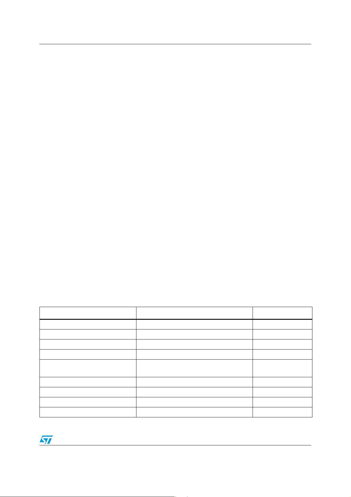
Table 1. Permissible values for unwanted emission intensity
f <= 710 MHz -36 dBm 100 kHz
710 MHz < f ≤ 900 MHz -55 dBm 1 MHz
900 MHz < f ≤ 915 MHz -55 dBm 100 kHz
915 MHz < f ≤ 920.3 MHz -36 dBm 100 kHz
920.3 MHz < f ≤ 924.3 MHz
(except for |f-fc| ≤ (200+100xn) kHz)
924.3 MHz < f ≤ 930 MHz -36 dBm 100 kHz
930 MHz < f ≤ 1000 MHz -55 dBm 100 kHz
1000 MHz < f ≤ 1215 MHz -45 dBm 1 MHz
1215 MHz < f -30 dBm 1 MHz
Frequency band Spurious emission strength (average power) Reference bandwidth
-55 dBm 100 kHz
Doc ID 023362 Rev 1 5/35
An overview of ARIB STD-T108 regulation AN4133
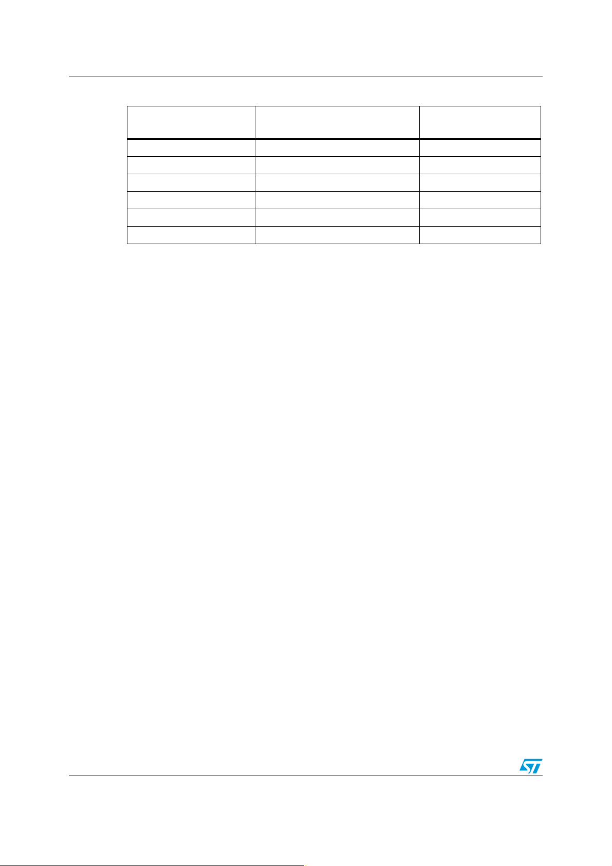
Table 2. Limit on secondary radiated emissions, etc. at receiver
Frequency band
f ≤ 710 MHz -54 dBm 100 kHz
710 MHz < f ≤ 900 MHz -55 dBm 1 MHz
900 MHz < f ≤ 915 MHz -55 dBm 100 kHz
915 MHz < f ≤ 930 MHz -54 dBm 100 kHz
930 MHz < f ≤ 1000 MHz -55 dBm 100 kHz
1000 MHz < f -47 dBm 1 MHz
Limit on secondary radiated
emissions, etc. (antenna input)
1.2 Low-power radio stations
Low-power radio stations differ from convenience radio stations in output power and usable
frequency band.
Regarding the output power, two different values are permitted as follows.
● An output power of 1 mW (0 dBm on a 50 ohm load, +3 dBm EIRP considering an
antenna of 3 dBi gain) is permitted in the band greater than or equal to 915.9 MHz to
less than or equal to 916.9 MHz , and greater than or equal to 920.5 MHz and less than
or equal to 929.7 MHz.
● An output power of 20 mW (+13 dBm on a 50 ohm load, +16 dBm EIRP considering an
antenna of 3 dBi gain) is permitted in the band greater than or equal to 920.5 MHz to
less than or equal to 928.1 MHz.
Reference bandwidth
As for convenience radio stations, an entire radio channel consists of up to 5 consecutive
unit radio channels which are defined such that their center frequency is located from 916.0
MHz to 916.8 MHz and from 920.6 MHz to 928.0 MHz with 200 kHz separation and a
bandwidth of 200 kHz, or which are defined such that their center frequency is located from
928.15 MHz to 929.65 MHz with 100 kHz separation and a bandwidth of 100 kHz. There
aren't specific requirements for the modulation method, while the permissible value for the
occupied bandwidth is (200 x n) kHz or less, where n is the number of unit radio channels
constituting the entire radio channel and is an integer from 1 to 5. In the case that the center
frequency is from 928.15 MHz to 929.65 MHz, it shall be (100 x n) kHz or less.
An adjacent channel leakage power is permitted: five different channel masks are defined,
functions of the usable bandwidth and of the output power. For the five different masks refer
to the figures 3-1 to 3-5 of the ARIB STD-T108 regulation, see References on page 33.
For the transmitter a permissible value for unwanted emission intensity is defined (see
Ta bl e 3 ).
For the receiver a limit for the secondary radiated emissions is defined (see Tab l e 4).
6/35 Doc ID 023362 Rev 1
AN4133 An overview of ARIB STD-T108 regulation
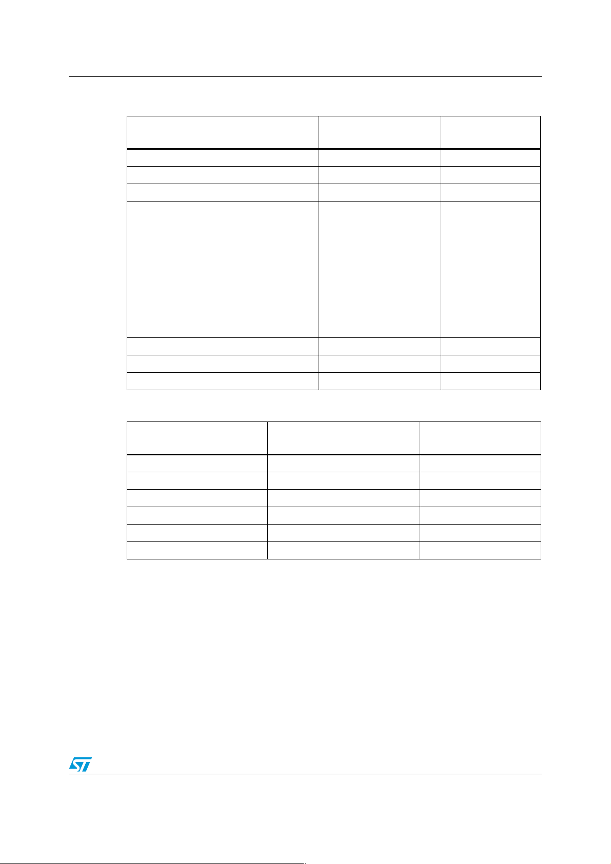
Table 3. Permissible values for unwanted emission intensity
Frequency band
f ≤ 710 MHz -36 dBm 100 kHz
710 MHz < f ≤ 900 MHz -55 dBm 1 MHz
900 MHz < f ≤ 915 MHz -55 dBm 100 kHz
915 MHz < f ≤ 930 MHz
(Except for |f-fc| ≤ (200+100xn) kHz if
bandwidth of unit radio channel is 200 kHz,
except for |f-fc| <= (100+50xn) kHz if the
bandwidth of unit radio channel is 100 kHz.
Except for |f-fc| <= (100+100xn) kHz if
frequency band is 915.9 MHz ≤ f ≤ 916.9 MHz
and 920.5 MHz ≤ f ≤ 922.3 MHz.
Where n is a number of unit radio channels
constituting the radio channel and is an
integer from 1 to 5).
930 MHz < f ≤ 1000 MHz -55 dBm 100 kHz
1000 MHz < f ≤ 1215 MHz -45 dBm 1 MHz
1215 MHz < f -30 dBm 1 MHz
Spurious emission
strength (average power)
-36 dBm 100 kHz
Reference bandwidth
Table 4. Limit on secondary radiated emissions, etc. at receiver
Frequency band
f ≤ 710 MHz -54 dBm 100 kHz
710 MHz < f ≤ 900 MHz -55 dBm 1 MHz
900 MHz < f ≤ 915 MHz -55 dBm 100 kHz
915 MHz < f ≤ 930 MHz -54 dBm 100 kHz
930 MHz < f ≤ 1000 MHz -55 dBm 100 kHz
1000 MHz < f -47 dBm 1 MHz
Limit on secondary radiated
emissions, etc. (antenna input)
Reference bandwidth
Doc ID 023362 Rev 1 7/35
Application circuit AN4133
2 Application circuit
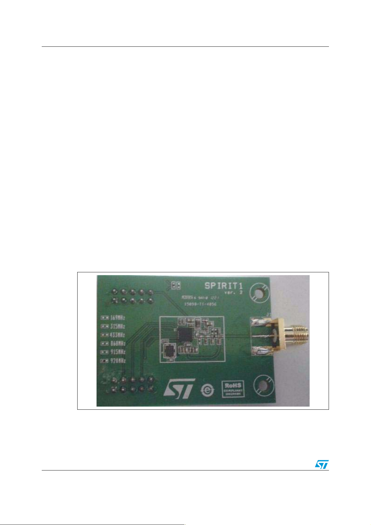
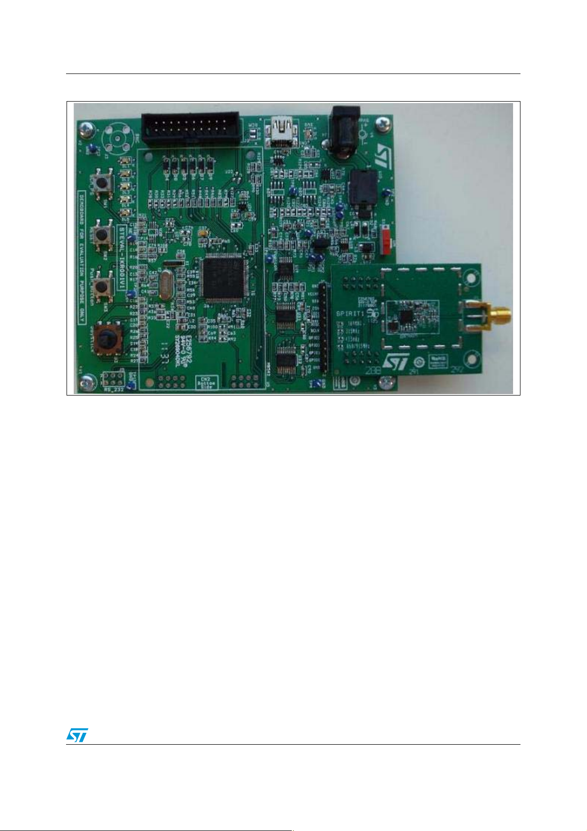
Figure 1 shows the SPIRIT1 application board. The application is composed of two boards:
a daughterboard and a motherboard. The daughterboard holds the SPIRIT1 with the circuits
necessary for operation. In order to function properly the daughterboard has to be plugged
into the motherboard (see Figure 2) using two header 5x2 connectors (J6 and J7).
The motherboard is provided with an STM32L152VBT6 microcontroller to correctly program
the transceiver. The microcontroller is programmed with firmware developed for the SPIRIT1
application. A graphical user interface (GUI) has been developed to correctly program the
SPIRIT1.
The daughterboard is provided with a 52 MHz crystal to provide the correct oscillator to the
SPIRIT1.
The SPIRIT1 has an internal SMPS that drastically reduces power consumption making the
SPIRIT1 the best in class for the application in this bandwidth. The SMPS is fed from the
battery (1.8 V to 3.6 V) and provides a programmable voltage (1.4 V usually) to the device.
An SMA connector is present to connect the board to the antenna or to the instrumentation
to verify the correct functionality and verify the ETSI standard request.
A few passive components (inductors and capacitors) are used for matching/filtering of the
power amplifier (PA) and balun network for the receiver.
To reduce the application cost the SPIRIT1 is designed to work without an external antenna
switch. This daughterboard is designed to show the functionality of the SPIRIT1 in this
condition. Of course an application with antenna switch can be implemented, but this isn't
described in this document.
Figure 1. SPIRIT1 application daughterboard
8/35 Doc ID 023362 Rev 1
AN4133 Application circuit
Figure 2. SPIRIT1 application daughterboard plugged into the motherboard
Doc ID 023362 Rev 1 9/35
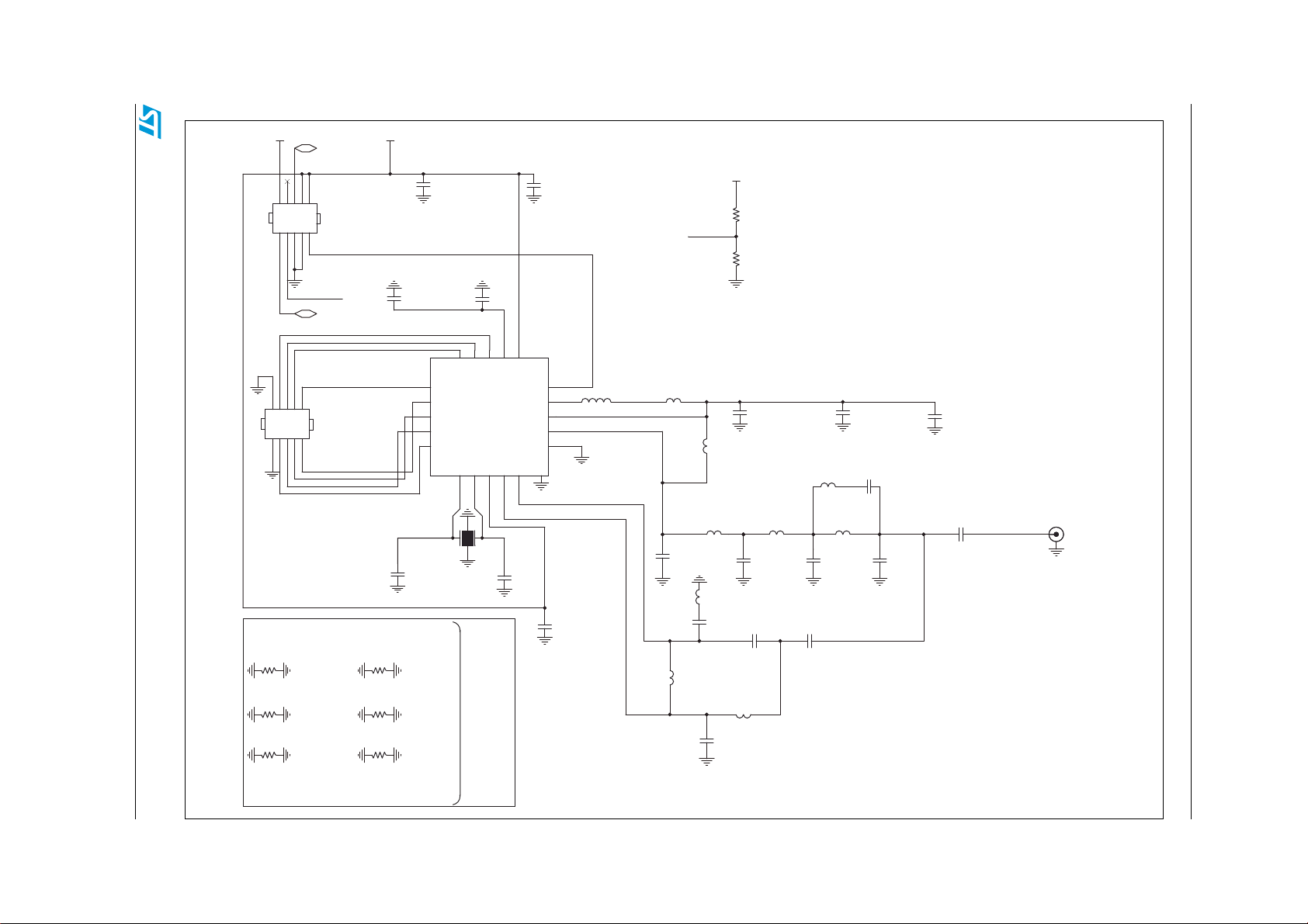
Figure 3. Daughterboard schematic
3V3
SPIRIT _DUMMY2
VCC_RF
AN4133 Application circuit
Doc ID 023362 Rev 1 10/35
246810
13579
246810
13579
R6
R6
R_0R0_0402
R_0R0_0402
R7
R7
R_0R0_0402
R_0R0_0402
R8
R8
R_0R0_0402
R_0R0_0402
DUMMY3
SPIRIT _DUMMY1
J7
J7
HEADER 5X2
HEADER 5X2
SCLK
B0=169MHz
B1=315MHz
B2=433MHz
J6
J6
HEADER 5X2
HEADER 5X2
GPIO3
GPIO2
GPIO1
GPIO0
SDO
SDI
CSn
SDn
C22
C22
C_330p_0402_C0G
C_330p_0402_C0G
U1
U1
1
2
3
4
5
SPIRIT 1_2
SPIRIT 1_2
NX3225GA-xxMHz (XTAL)
C9
C9
C_12P_0402_C0G_J_50
C_12P_0402_C0G_J_50
R9
R9
R10
R10
R11
R11
R_0R0_0402
R_0R0_0402
R_0R0_0402
R_0R0_0402
R_0R0_0402
R_0R0_0402
B3=868MHz
B3=915MHz
B3=920MHz
C20
C20
C_1U_0603_X7R_K_6V3
C_1U_0603_X7R_K_6V3
C0
C0
C_100n_0402_X7R
C_100n_0402_X7R
20
GPIO_0
SDO
SDI
SCLK
CSn
GPIO_318GPIO_219GPIO_1
VBAT2
XOUT6XIN7RXP9RXN
8
Y1
XTALY1XTAL
Mount
resistor
relative to
used band
C21
C21
C_100p_0402_C0G
C_100p_0402_C0G
17
16
VREG
VBAT1
15
SDn
14
SMPS1
13
SMPS2
12
TX
11
REXT
GND
10
21
C10
C10
C_10P_0402_C0G_J_50
C_10P_0402_C0G_J_50
L_10U_0805
L_10U_0805
C19
C19
C_TBD_0402_C0G
C_TBD_0402_C0G
3V3
R12
R12
R_TBD_0402
L0
L0
L_TBD_0402_50M
L_TBD_0402_50M
L1
L1
C_TBD_0402_C0G
C_TBD_0402_C0G
L4
L4
L_TBD_0402
L_TBD_0402
C_TBD_0402_C0G
C_TBD_0402_C0G
R_TBD_0402
R13
R13
R_TBD_0402
R_TBD_0402
C11
C11
C_1U_0603_X7R_ K_6V3
C_1U_0603_X7R_ K_6V3
L2
L2
L_TBD_0402
L_TBD_0402
C1
C1
C_TBD_0402_C0G
C_TBD_0402_C0G
C5
C5
C12
C12
C_100n_0402_X7R
C_100n_0402_X7R
L9
L9
C14 C_TBD_0402_C0GC14 C_TBD_0402_C0G
L_TBD_0402
L_TBD_0402
L3 L_TBD_0402L3 L_TBD_0402
C2
C2
C_TBD_0402_C0G
C_TBD_0402_C0G
C7
C7
C_TBD_0402_C0G
C_TBD_0402_C0G
C3
C3
C_TBD_0402_C0G
C_TBD_0402_C0G
C13
C13
C_TBD_0402_X7R
C_TBD_0402_X7R
C8
C8
C_TBD_0402_C0G
C_TBD_0402_C0G
RF_IN/OUT
RF_IN/OUT
J1
J1
DUMMY3
L8
L7
L7
L8
L_TBD_0402
L_TBD_0402
L_TBD_0402
L_TBD_0402
C15
C15
C_TBD_0402_C0G
C_TBD_0402_C0G
L5 L_TBD_0402L5 L_TBD_0402
C6 C_TBD_0402_C0GC6 C_TBD_0402_C0G
L6
L6
L_TBD_0402
L_TBD_0402
C4
C4

AN4133 Transmitter
3 Transmitter
All the measurements given are measured under the following conditions: Tc = 25 °C, Vdd =
3.0 V, f = 922 MHz (middle frequency of the bandwidth used), unless otherwise specified.
The maximum output power of the SPIRIT1 in this band is 10 dBm, so all the measurements
for the convenience radio stations and low-power radio stations with +24 dBm or +13 dBm
output power will be performed at +10 dBm. Low-power radio stations with output power of 0
dBm will be performed with the correct output power.
A radio channel consists of up to 5 consecutive unit radio channels which are defined such
that their center frequency is located from 920.6 MHz to 923.4 MHz with 200 kHz separation
and a bandwidth of 200 kHz. SPIRIT1 fully supports the center frequency, separation and
bandwidth requirements. No measurement in that sense will be done.
There aren't specific requirements for the modulation method, while the permissible value
for the occupied bandwidth is (200 x n) kHz or less, where n is the number of unit radio
channels constituting the entire radio channel and is an integer from 1 to 5. The
measurement in this case will be done with a GFSK (BT = 0.5) modulation with 100 kbps
data rate, 50 kHz frequency deviation. Different combinations of modulation, data rate and
frequency deviation creates signals that have a bandwidth lower than 200 kHz: a specific
check has to be done for each case.
There are no specific requirements in the standard about setting the detector, resolution
bandwidth (RBW) or video bandwidth (VBW) of the spectrum analyzer. The detector will be
set to peak, the resolution and video bandwidths will be set sufficiently large to ensure the
correctness of the measurement, and the display will be set to peak hold.
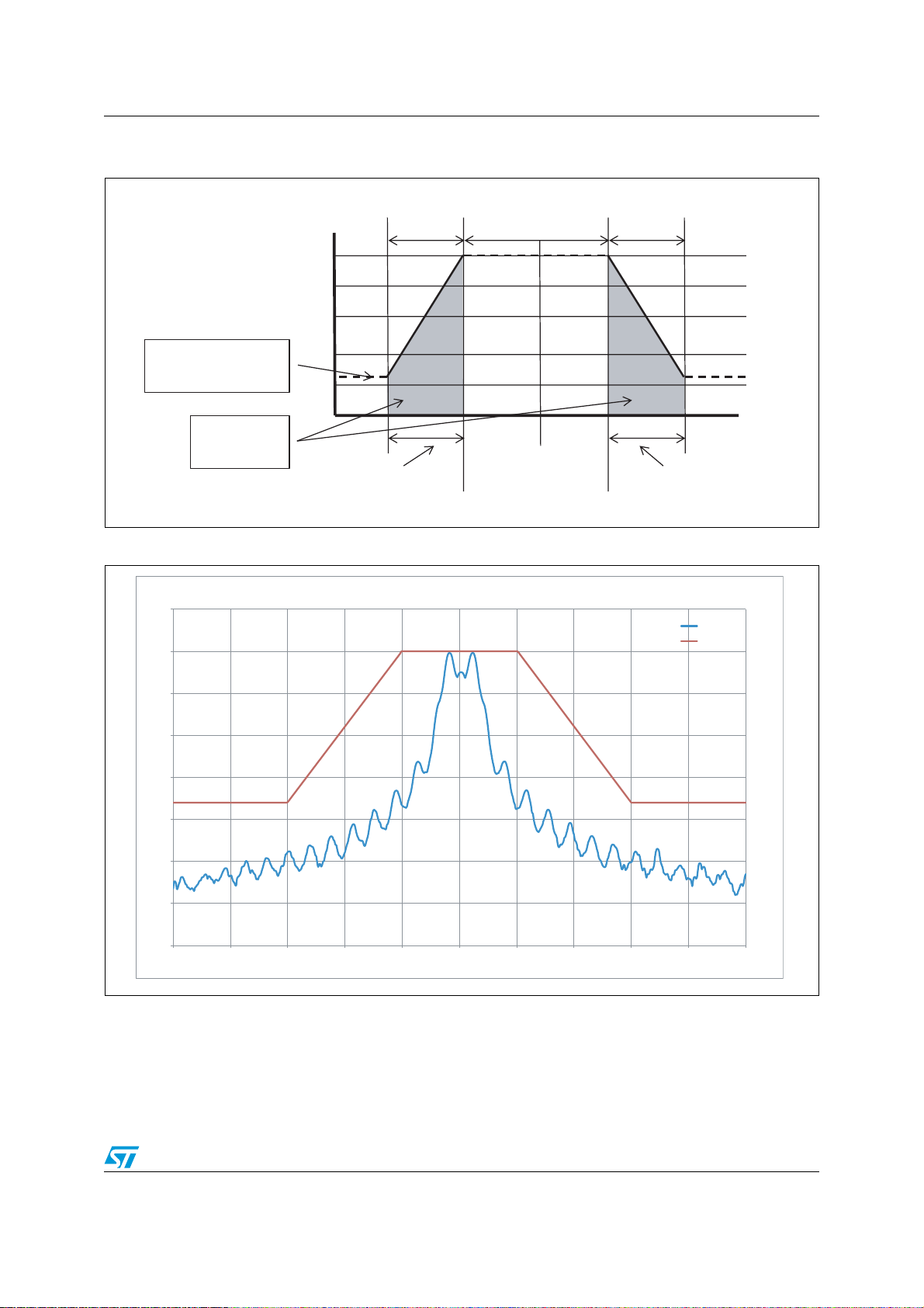
3.1 Adjacent channel leakage power
The adjacent channel leakage power is defined as the amount of the modulated RF signal
power which falls within a given adjacent channel. This power is the sum of the mean power
produced by the modulation, hum and noise of the transmitter.
Different masks are defined for the two types of operating modes. For the convenience radio
stations the masks given in Figure 4 and 6 are defined. The first one defines the channel
mask of a radio channel whose frequency is from 920.5 MHz to 922.3 MHz. The second one
defines the channel mask of a radio channel whose frequency is from 922.3 MHz to 923.5
MHz. The max output power permitted for the convenience radio station is 250 mW (+24
dBm), the SPIRIT1 doesn't support this output power, so the mask compliance is verified
with an output power of 10 dBm. An external PA should be used to reach the maximum
output power.
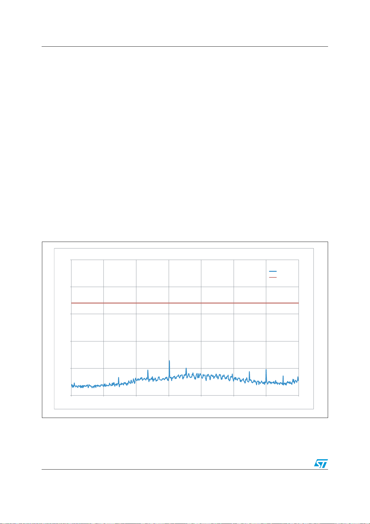
Figure 5 and 7 show the compliance measurement with the two masks and that the SPIRIT1
complies. If an external power amplifier is used to burst the output power to +24 dBm a
verification of the channel masks has to be done. If the mask requirements aren't met, a
reduction of the data rate and/or frequency deviation is necessary.
For the low-power radio stations the masks printed in Figure 8, 10, 12, 14, and 16 are
defined.
Figure 8 defines the channel mask of a radio channel whose frequency is from 915.9 MHz
to 916.9 MHz. In this case the maximum permitted output power is 1 mW (0 dBm), so the
measurement is performed with this output power level. Figure 9 shows the SPIRIT1
Doc ID 023362 Rev 1 11/35

Transmitter AN4133
compliance with the mask, the measurement is performed with the center frequency set to
916.5 MHz.
Figure 10 defines the channel mask of a radio channel whose frequency is from 920.5 MHz
to 922.3 MHz. The max output power permitted for this bandwidth is 20 mW (+13 dBm), the
SPIRIT1 doesn't support this output power, so the mask compliance is verified with an
output power of 10 dBm. In Figure 11 the SPIRIT1 compliance mask is shown. The output
power is set to 7 dBm to enter on the mask. To work with a higher output power, a reduction
of the data rate and/or frequency deviation is necessary. The center frequency is set to
921.5 MHz.
Figure 12 and 14 define the channel masks of a radio channel whose frequency is from
922.3 MHz to 928.1 MHz. The compliance mask measurements are shown respectively in
Figure 13 and15. The measurements are performed with the center frequency set to
928 MHz and 925 MHz respectively.
The mask in Figure 16 is defined for maximum permitted output power of 1 mW (0 dBm) of a
radio channel whose frequency is from 928.1 MHz to 929.7 MHz. The measurement is
performed with SPIRIT1 set to provide this output power level. Figure 17 shows the
compliance with the mask. The measurement is performed with the center frequency set to
929 MHz.
12/35 Doc ID 023362 Rev 1

AN4133 Transmitter
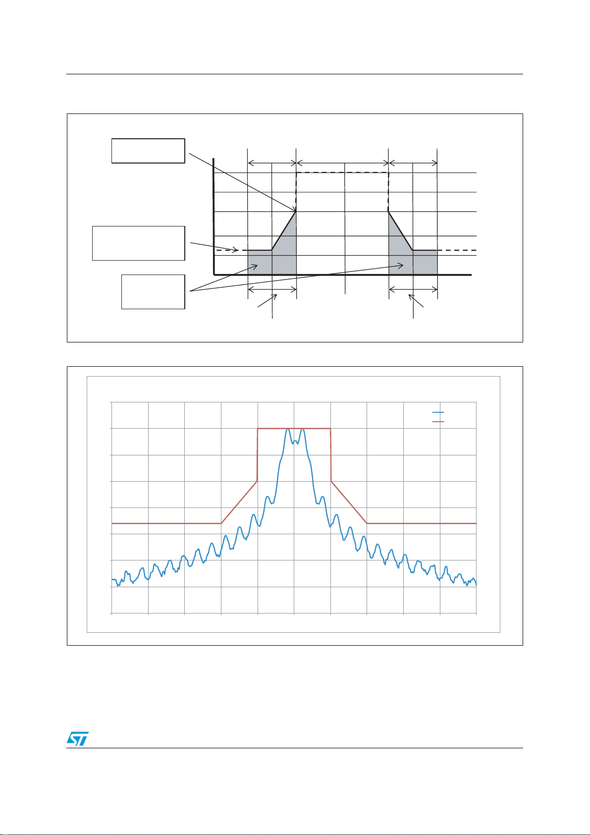
Figure 4. Convenience radio station channel mask of a radio channel whose frequency is from
920.5 MHz to 922.3 MHz
Unit: dBm/100kHz
200 kHz 200 kHz(200 x n) kHz
30
Power at the edge:
+4 d Bm o r les
s
20
10
0
Spurious emission strength
(920.3 MHz to 924.3 MHz)
-29 dBm/100 kH
z
-10
-20
-30
-40
0
-5
Adj a cent cha nne l
leakage power:
-5 d Bm o r less
Lower adja cen t
unit channe
l
f
c
(Center frequency)
Upp er adj a cent
unit channel
fc-200-100x(n-1) fc+20 0+100x (n-1)
Figure 5. Convenience radio station channel mask of a radio channel at 922 MHz
Unit:
kHz
Convenience radio station 10 dBm 920.5 MHz to 922.3 MHz bandwidth
30
Spirit
20
10
0
-10
Output power [dBm]
-20
-30
-40
-50
9.215E+08 9.216E+08 9.217E+08 9.218E+08 9.219E+08 9.220E+08 9.221E+08 9.222E+08 9.223E+08 9.224E+08 9.225E+08
Frequency [Hz]
ARIB Mask
Doc ID 023362 Rev 1 13/35

Transmitter AN4133
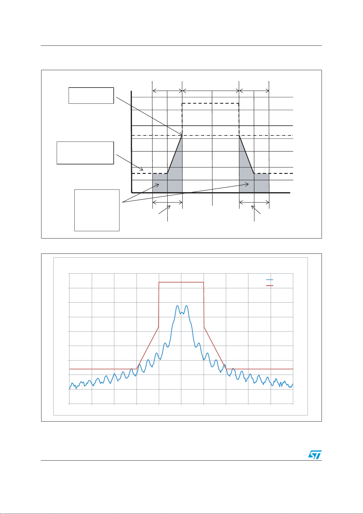
Figure 6. Convenience radio station channel mask of a radio channel whose frequency is from
922.3 MHz to 923.5 MHz
Unit: dBm/100kH
z
200 kHz 200 kHz(200 x n) kHz
30
20
10
0
Spurious emission strength
(920.3 MHz to 924.3 MHz)
-29 dBm/100 kH
z
-10
-20
-30
-40
0
-5
Adj a cent cha nnel
lea ka ge p ower:
-5 d Bm o r less
Lower adja cent
unit channe
l
f
c
(Center frequency)
Upp er a dja cen t
unit channel
fc-100xn fc+100xn
Figure 7. Convenience radio station channel mask of a radio channel at 923 MHz
Unit:
kHz
Convenience radio station 10 dBm 922.3 MHz to 923.5 MHz bandwidth
30
Spirit
20
10
0
-10
Output power [dBm]
-20
-30
-40
-50
9.225E+08 9.226E+08 9.227E+08 9.228E+08 9.229E+08 9.230E+08 9.231E+08 9.232E+08 9.233E+08 9.234E+08 9.235E+08
Frequency [Hz]
ARIB Mask
14/35 Doc ID 023362 Rev 1
AN4133 Transmitter
Figure 8. Low-power radio station channel mask of a radio channel whose frequency is from
915.9 MHz to 916.9 MHz
Unit: dBm/100kHz
Power at the edge:
-20 dBm or les
s
200 kHz 200 kHz(200 x n) kHz
0
-10
-20
Spurious emission strength
-30
(915 MHz to 930 MHz)
-36 dBm/100 kH
z
-40
-5
0
Adj a cent cha nne l
leakagepower:
-26 dBm or les
s
Lower adja cent
unit channe
l
f
-200-100x(n-1) fc+200+100x(n-1)
c
f
c
(Center frequency)
Upp er a djacent
unit channel
Figure 9. Low-power radio station channel mask of a radio channel at 916.5 MHz
Low-power radio station 0 dBm 915.9 MHz to 916.9 MHz bandwidth
10
Spirit
0
ARIB Mask
Unit:
kHz
-10
-20
-30
Output power [dBm]
-40
-50
-60
-70
9.160E+08 9.161E+08 9.162E+08 9.163E+08 9.164E+08 9.165E+08 9.166E+08 9.167E+08 9.168E+08 9.169E+08 9.170E+08
Frequency [Hz]
Doc ID 023362 Rev 1 15/35
Transmitter AN4133
Figure 10. Low-power radio station channel mask of a radio channel whose frequency is from
920.5 MHz to 922.3 MHz
Unit: dBm/100kHz
200 kHz 200 kHz(200 x n) kHz
Power at the edge:
-7 d Bm o r les
s
Spurious emission strength
(920.3 MHz to 924.3 MHz)
-36 dBm/100 kHz
Adjacentchannel
lea ka ge po wer:
-15 dBm or less
(If the case of 1 mW
or less, -26 dBm or
less
)
20
10
0
-10
-20
-30
-40
-5
0
Lower adja cent
unit channe
f
l
f
-200-100x(n-1) fc+200+100x(n-1)
c
(Center frequency)
c
Upp er a dja cen t
unit channel
Figure 11. Low-power radio station channel mask of a radio channel at 921.5 MHz
Unit:
kHz
Low-power radio station 7 dBm 920.5 MHz to 922.3 MHz bandwidth
30
Spirit
20
10
0
-10
-20
Output power [dBm]
-30
-40
-50
-60
9.210E+08 9.211E+08 9.212E+08 9.213E+08 9.214E+08 9.215E+08 9.216E+08 9.217E+08 9.218E+08 9.219E+08 9.220E+08
Frequency [Hz]
ARIB Mask
16/35 Doc ID 023362 Rev 1
AN4133 Transmitter
Figure 12. Low-power radio station channel mask of a radio channel whose frequency is from
922.3 MHz to 928.1 MHz (antenna power is 1 mW or less)l
Unit: dBm/100kHz
200 kHz 200 kHz(200 x n) kHz
0
-10
-20
Spurious emission strength
-30
(915 MHz to 930 MHz)
-36 dBm/100 kHz
-40
-5
0
Adj a cent cha nne l
lea ka ge p ower:
-26 dBm or less
Lower adja cent
unit channe
l
f
-100xn fc+10 0xn
c
f
c
(Center frequency)
Upp er a djacent
unit channel
Figure 13. Low-power radio station channel mask of a radio channel at 928 MHz
Low-power radio station 0 dBm 922.3 MHz to 928.1 MHz bandwidth
10
0
-10
-20
-30
Unit:
kHz
Spirit
ARIB Mask
Output power [dBm]
-40
-50
-60
-70
9.275E+08 9.276E+08 9.277E+08 9.278E+08 9.279E+08 9.280E+0 8 9.281E+08 9.282E+08 9.283E+08 9.284E+08 9.285E+08
Frequency [Hz]
Doc ID 023362 Rev 1 17/35

Transmitter AN4133
Figure 14. Low-power radio station channel mask of a radio channel whose frequency is from
922.3 MHz to 928.1 MHz (antenna power is more than 1 mW and 20 mW or less)
Unit: dBm/100kH
z
200 kHz 200 kHz(200 x n) kHz
20
10
0
-10
Spurious emission strength
(915 MHz to 930 MHz)
-20
-36 dBm/100 kHz
-30
-40
Adjacentchannel
-50
lea ka ge po wer:
-15 dBm or less
Lower adja cen t
unit channe
l
-100xn fc+100xn
f
c
f
c
(Ce nte r freq ue ncy )
Upp er a djacent
unit channel
Figure 15. Low-power radio station channel mask of a radio channel at 925 MHz
Unit:
kHz
Low-power radio station 10 dBm 922.3 MHz to 928.1 MHz bandwidth
30
Spirit
20
10
0
-10
Output power [dBm]
-20
-30
-40
-50
9.245E+08 9.246E+08 9.247E+08 9.248E+08 9.249E+08 9.250E+08 9.251E+08 9.252E+08 9.253E+08 9.254E+08 9.255E+08
Frequency [Hz]
ARIB Mask
18/35 Doc ID 023362 Rev 1

AN4133 Transmitter
Figure 16. Low-power radio station channel mask of a radio channel whose frequency is from
928.1 MHz to 929.7 MHz
Unit: dBm/100kHz
100 kHz 100 kHz(100 x n) kHz
0
-10
-20
Spurious emission strength
-30
(915 MHz to 930 MHz)
-36 dBm/100 kHz
-40
-5
0
Adj a cent cha nne l
lea ka ge po wer:
-26 dBm or less
Lower adja cen t
unit channe
l
f
-50xn fc+50 xn
c
f
c
(Center frequency)
Upp er a djacent
unit channel
Figure 17. Low-power radio station channel mask of a radio channel at 929 MHz
Low-power radio station 0 dBm 928.1 MHz to 929.7 MHz bandwidth
10
0
-10
-20
-30
Unit:
kHz
Spirit
ARIB Mask
Output power [dBm]
-40
-50
-60
-70
9.285E+08 9.286E+0 8 9.287E+08 9.288E+0 8 9.289E+08 9.290 E+08 9.291E+08 9.292E+08 9.293E+08 9.294E+08 9.295E+08
Frequency [Hz]
Doc ID 023362 Rev 1 19/35
Permissible values for unwanted emission intensity AN4133
4 Permissible values for unwanted emission intensity
Unwanted emissions in the spurious domain are emissions at a frequency other than those
of the desired carrier frequency and its sidebands associated with normal test modulation.
The spurious emission strength at the antenna input has to be less than the values in
Ta bl e 1 for the convenience radio stations and Ta bl e 3 for the low-power radio station. The
measurements for the convenience radio station are done with the carrier set to 922 MHz.
The measurements for the low-power radio station are done with the carrier set to
916.5 MHz.
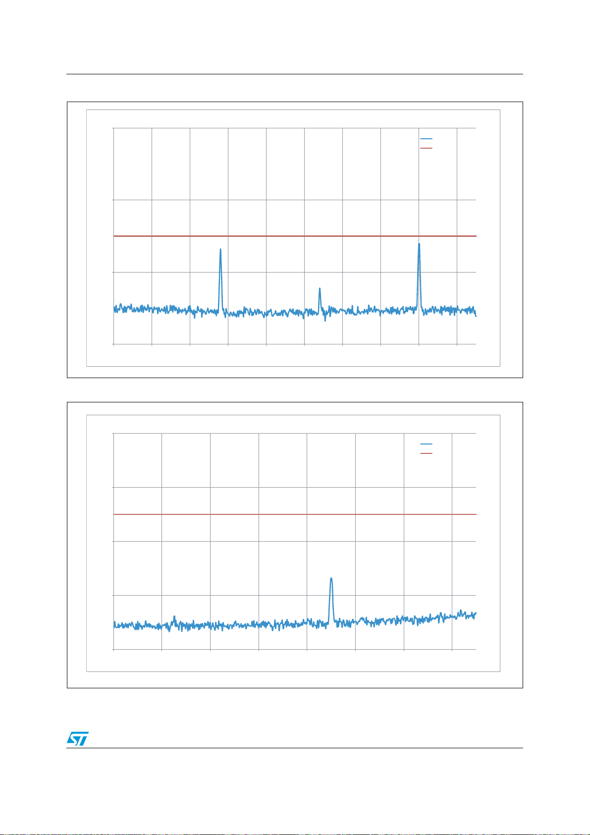
The measurements performed for the convenience radio station are given in Figure 18 to 26
which show that all requirements are met. Special attention must be given to the
requirement in the 920.3 to 924.3 MHz band. In this band the levels of the spurious have to
be lower than -55 dBm on 100 kHz band without considering the channel occupied
bandwidth. This value is in obvious contradiction with the value reported in the convenience
radio station channel masks (Figure 4 and 6) where for the same spurious a maximum level
of -29 dBm integrated in 100 kHz bandwidth is given. In Figure 22 the two different masks
are shown and it is clear that the second requirement is much less stringent than the first
one.
The measurements performed for the low-power radio station are given in Figure 27 to 33.
For the low-power case the full requirements are met.
Figure 18. Convenience radio station emission in the 10 - 710 MHz bandwidth
-20
-30
-40
-50
Output power [dBm]
-60
-70
1.00E+07 1.10E+08 2.10E+08 3.10E+08 4.10E+08 5.10E+08 6.10E+08 7.10E+08
Convenience radio station spurious emission 10 - 710 MHz
Frequency [Hz]
Spirit
ARIB mask
20/35 Doc ID 023362 Rev 1
AN4133 Permissible values for unwanted emission intensity
Figure 19. Convenience radio station emission in the 710 - 900 MHz bandwidth
-40
-50
Convenience radio station spurious emission 710 - 900 MHz
Output power [dBm]
-60
-70
7.10E+08 7.30E+08 7.50E+08 7.70E+08 7.90E+08 8.10E+08 8.30E+08 8.50E+08 8.70E+08 8.90E+08
Frequency [Hz]
Figure 20. Convenience radio station emission in the 900 - 915 MHz bandwidth
Spirit
ARIB mask
-40
-50
-60
Convenience radio station spurious emission 900 - 915 MHz
Spirit
ARIB mask
Output power [dBm]
-70
-80
9.00E+08 9.02E+08 9.04E+08 9.06E+08 9.08E+08 9.10E+08 9.12E+08 9.14E+08
Frequency [Hz]
Doc ID 023362 Rev 1 21/35

Permissible values for unwanted emission intensity AN4133
Figure 21. Convenience radio station emission in the 915 - 920.3 MHz bandwidth
-30
-40
-50
-60
Output power [dBm]
-70
-80
9.15E+08 9.16E+08 9.17E+08 9.18E+08 9.19E+08 9.20E+08
Convenience radio station spurious emission 915 - 920.3 MHz
Frequency [Hz]
Figure 22. Convenience radio station emission in the 920.3 - 924.3 MHz bandwidth
Spirit
ARIB mask
20
10
0
-10
-20
-30
Convenience radio station spurious emission 920.3 - 924.3 MHz
Spirit
ARIB table
ARIB mask
Output power [dBm]
-40
-50
-60
-70
9.20E+08 9.21E+08 9.21E+08 9.22E+08 9.22E+08 9.23E+08 9.23E+08 9.24E+08 9.24E+08
Frequency [Hz]
22/35 Doc ID 023362 Rev 1

AN4133 Permissible values for unwanted emission intensity
Figure 23. Convenience radio station emission in the 924.3 - 930 MHz bandwidth
-30
-40
-50
-60
Convenience radio station spurious emission 924.3 - 930 MHz
Output power [dBm]
-70
-80
-90
9.24E+08 9.25E+08 9.26E+08 9.27E+08 9.28E+08 9.29E+08
Frequency [Hz]
Figure 24. Convenience radio station emission in the 930 - 1000 MHz bandwidth
Spirit
ARIB mask
-30
-40
-50
-60
Convenience radio station spurious emission 930 MHz - 1 GHz
Output power [dBm]
-70
-80
-90
9.30E+08 9.40E+08 9.50E+08 9.60E+08 9.70E+08 9.80E+08 9.90E+08
Frequency [Hz]
Spirit
ARIB mask
Doc ID 023362 Rev 1 23/35

Permissible values for unwanted emission intensity AN4133
Figure 25. Convenience radio station emission in the 1 - 1.215 GHz bandwidth
-30
-40
-50
-60
Convenience radio station spurious emission 1 - 1.215 GHz
Output power [dBm]
-70
-80
-90
1.00E+09 1.05E+09 1.10E+09 1.15E+09 1.20E+09
Frequency [Hz]
Figure 26. Convenience radio station emission in the 1.215 - 6 Hz bandwidth
Spirit
ARIB mask
-20
-30
-40
-50
Output power [dBm]
-60
-70
1.22E+09 2.22E+09 3.22E+09 4.22E+09 5.22E+09
Convenience radio station spurious emission 1.215 - 6 GHz
Frequency [Hz]
Spirit
ARIB mask
24/35 Doc ID 023362 Rev 1

AN4133 Permissible values for unwanted emission intensity
Figure 27. Low-power radio station emission in the 10 - 710 MHz bandwidth
-20
-30
-40
-50
-60
Low-power radio station spurious emission 10 - 710 MHz
Output power [dBm]
-70
-80
-90
1.00E+07 1.10E+08 2.10E+08 3.10E+08 4.10E+08 5.10E+08 6.10E+08 7.10E+08
Frequency [Hz]
Figure 28. Low-power radio station emission in the 710 - 900 MHz bandwidth
Spirit
ARIB mask
-50
-60
Low-power radio station spurious emission 710 - 900 MHz
Spirit
ARIB mask
Output power [dBm]
-70
7.10E+08 7.30E+08 7.50E+08 7.70E+08 7.90E+08 8.10E+08 8.30E+08 8.50E+08 8.70E+08 8.90E+08
Frequency [Hz]
Doc ID 023362 Rev 1 25/35

Permissible values for unwanted emission intensity AN4133
Figure 29. Low-power radio station emission in the 900 - 915 MHz bandwidth
-50
-60
Low-power radio station spurious emission 900 - 915 MHz
Output power [dBm]
-70
-80
9.00E+08 9.02E+08 9.04E+08 9.06E+08 9.08E+08 9.10E+08 9.12E+08 9.14E+08
Frequency [Hz]
Figure 30. Low-power radio station emission in the 915 - 930 MHz bandwidth
Spirit
ARIB mask
10
0
-10
-20
-30
-40
-50
Output power [dBm]
-60
-70
-80
-90
9.15E+08 9.16E+08 9.17E+08 9.18E+08 9.19E+08 9.20E+08
Low-power radio station spurious emission 915 - 930 MHz
Spirit
ARIB mask
Frequency [Hz]
26/35 Doc ID 023362 Rev 1

AN4133 Permissible values for unwanted emission intensity
Figure 31. Low-power radio station emission in the 930 - 1000 MHz bandwidth
-50
-60
Low-power radio station spurious emission 930 MHz - 1 GHz
Output power [dBm]
-70
-80
9.30E+08 9.40E+08 9.50E+08 9.60E+08 9.70E+08 9.80E+08 9.90E+08
Frequency [Hz]
Figure 32. Low-power radio station emission in the 1 - 1.215 GHz bandwidth
Spirit
ARIB mask
-40
-50
Low-power radio station spurious emission 1 - 1.215 GHz
Output power [dBm]
-60
-70
1.00E+09 1.05E+09 1.10E+09 1.15E+09 1.20E+09
Frequency [Hz]
Spirit
ARIB mask
Doc ID 023362 Rev 1 27/35

Permissible values for unwanted emission intensity AN4133
Figure 33. Low-power radio station emission in the 1.215 - 6 GHz bandwidth
-20
-30
-40
-50
Output power [dBm]
-60
-70
1.22E+09 2.22E+09 3.22E+09 4.22E+09 5.22E+09
Low-power radio station spurious emission 1.215 - 6 GHz
Frequency [Hz]
Spirit
ARIB mask
28/35 Doc ID 023362 Rev 1

AN4133 Receiver
5 Receiver
Only one measurement is required for the receiver, the limit on secondary radiated
emission. This measurement is performed under the following conditions: Tc = 25 °C,
Vdd = 3.0 V, f = 922 MHz (middle frequency of the bandwidth used).
5.1 Limit on secondary radiated emission
Spurious radiation from the receiver includes components at any frequency, radiated by the
equipment. The spurious emission strength at the antenna input has to be less than the
values in Ta bl e 2 for the convenience radio stations and Ta bl e 4 for the low-power radio
stations. The two tables are the same, so the measurement is performed only once, setting
the receiver to 922 MHz, maximum gain.
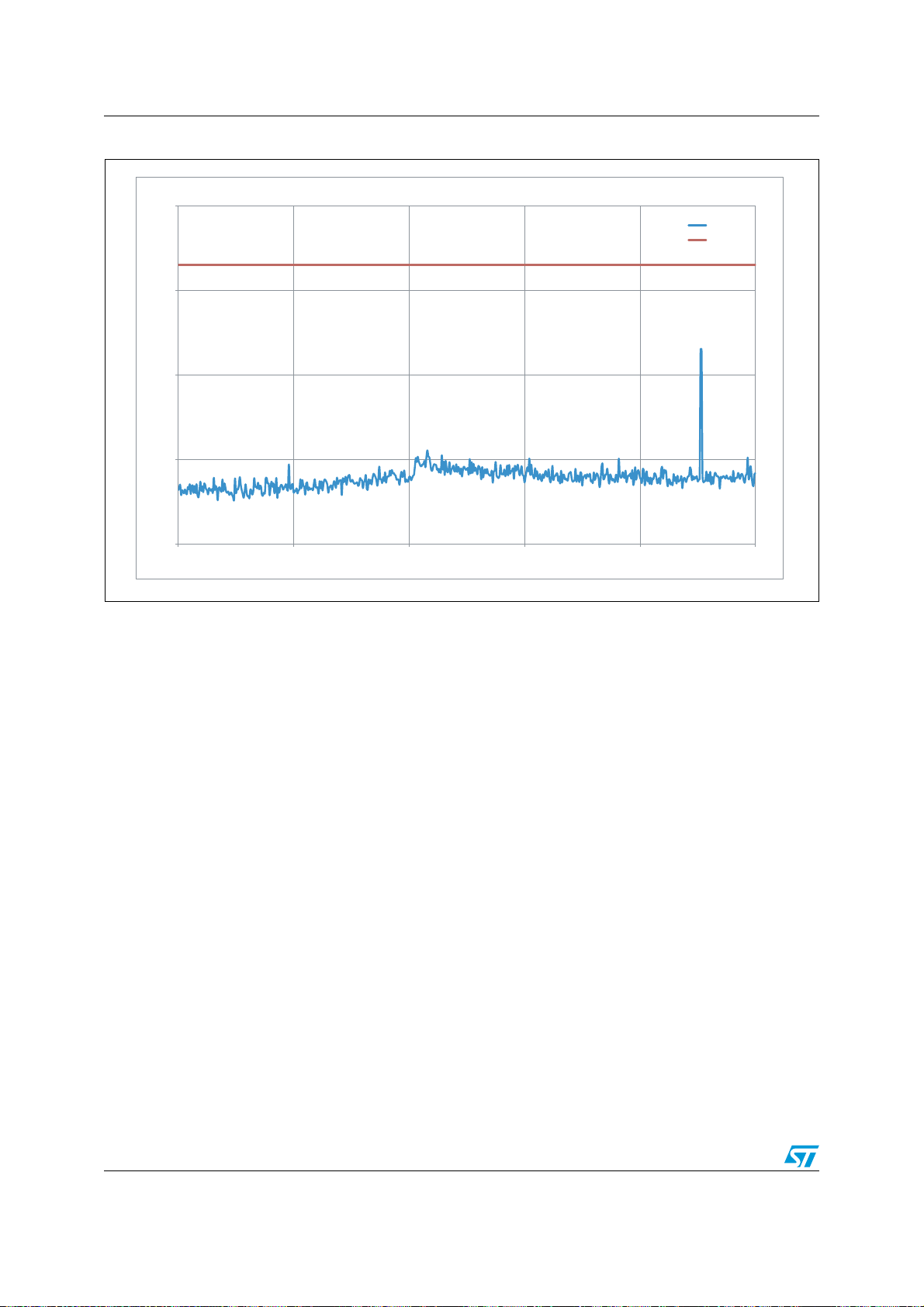
The measurement results are given in Figure 34 to 39. The entire standard requirements
are met from the SPIRIT1 in receiver mode.
Figure 34. Receiver radiated emission in the 10 - 710 MHz bandwidth
-40
-50
-60
-70
-80
Output power [dBm]
-90
-100
-110
1.00E+07 1.10E+08 2.10E+08 3.10E+08 4.10E+08 5.10E+08 6.10E+08 7.10E+08
Convenience radio station receiver spurious emission 10 - 710 MHz
Spirit
ARIB mask
Frequency [Hz]
Doc ID 023362 Rev 1 29/35

Receiver AN4133
Figure 35. Receiver radiated emission in the 710 - 900 MHz bandwidth
-40
-50
-60
-70
Output power [dBm]
-80
-90
7.10E+08 7.30E+08 7.50E+08 7.70E+08 7.90E+08 8.10E+08 8.30E+08 8.50E+08 8.70E+08 8.90E+08
Convenience radio station receiver spurious emission 710 - 900 MHz
Frequency [Hz]
Figure 36. Receiver radiated emission in the 900 - 915 MHz bandwidth
Spirit
ARIB mask
-40
-50
-60
-70
Convenience radio station receiver spurious emission 900 - 915 MHz
Spirit
ARIB mask
Output power [dBm]
-80
-90
-100
9.00E+08 9.02E+08 9.04E+08 9.06E+08 9.08E+08 9.10E+08 9.12E+08 9.14E+08
Frequency [Hz]
30/35 Doc ID 023362 Rev 1

AN4133 Receiver
Figure 37. Receiver radiated emission in the 915 - 930 MHz bandwidth
-30
-40
-50
-60
-70
Convenience radio station receiver spurious emission 915 - 930 MHz
Output power [dBm]
-80
-90
-100
9.15E+08 9.17E+08 9.19E+08 9.21E+08 9.23E+08 9.25E+08 9.27E+08 9.29E+08
Frequency [Hz]
Figure 38. Receiver radiated emission in the 930 - 1000 MHz bandwidth
Spirit
ARIB mask
-50
-60
-70
-80
Output power [dBm]
-90
-100
9.30E+08 9.40E+08 9.50E+08 9.60E+08 9.70E+08 9.80E+08 9.90E+08
Convenience radio station receiver spurious emission 930 MHz - 1 GHz
Frequency [Hz]
Spirit
ARIB mask
Doc ID 023362 Rev 1 31/35
Receiver AN4133
Figure 39. Receiver radiated emission in the 1 - 6 GHz bandwidth
-40
-50
-60
Convenience radio station receiver spurious emission 1 - 6 GHz
Spirit
ARIB mask
Output power [dBm]
-70
-80
1.00E+09 2.00E+09 3.00E+09 4.00E+09 5.00E+09 6.00E+09
Frequency [Hz]
32/35 Doc ID 023362 Rev 1

AN4133 References
6 References
1. SPIRIT1 datasheet
2. ARIB STD-T108: "920 MHz band telemeter, telecontrol and data transmission radio
equipment"
Doc ID 023362 Rev 1 33/35
Revision history AN4133
7 Revision history
Table 5. Document revision history
Date Revision Changes
12-Jul-2012 1 Initial release.
34/35 Doc ID 023362 Rev 1

AN4133
Please Read Carefully:
Information in this document is provided solely in connection with ST products. STMicroelectronics NV and its subsidiaries (“ST”) reserve the
right to make changes, corrections, modifications or improvements, to this document, and the products and services described herein at any
time, without notice.
All ST products are sold pursuant to ST’s terms and conditions of sale.
Purchasers are solely responsible for the choice, selection and use of the ST products and services described herein, and ST assumes no
liability whatsoever relating to the choice, selection or use of the ST products and services described herein.
No license, express or implied, by estoppel or otherwise, to any intellectual property rights is granted under this document. If any part of this
document refers to any third party products or services it shall not be deemed a license grant by ST for the use of such third party products
or services, or any intellectual property contained therein or considered as a warranty covering the use in any manner whatsoever of such
third party products or services or any intellectual property contained therein.
UNLESS OTHERWISE SET FORTH IN ST’S TERMS AND CONDITIONS OF SALE ST DISCLAIMS ANY EXPRESS OR IMPLIED
WARRANTY WITH RESPECT TO THE USE AND/OR SALE OF ST PRODUCTS INCLUDING WITHOUT LIMITATION IMPLIED
WARRANTIES OF MERCHANTABILITY, FITNESS FOR A PARTICULAR PURPOSE (AND THEIR EQUIVALENTS UNDER THE LAWS
OF ANY JURISDICTION), OR INFRINGEMENT OF ANY PATENT, COPYRIGHT OR OTHER INTELLECTUAL PROPERTY RIGHT.
UNLESS EXPRESSLY APPROVED IN WRITING BY TWO AUTHORIZED ST REPRESENTATIVES, ST PRODUCTS ARE NOT
RECOMMENDED, AUTHORIZED OR WARRANTED FOR USE IN MILITARY, AIR CRAFT, SPACE, LIFE SAVING, OR LIFE SUSTAINING
APPLICATIONS, NOR IN PRODUCTS OR SYSTEMS WHERE FAILURE OR MALFUNCTION MAY RESULT IN PERSONAL INJURY,
DEATH, OR SEVERE PROPERTY OR ENVIRONMENTAL DAMAGE. ST PRODUCTS WHICH ARE NOT SPECIFIED AS "AUTOMOTIVE
GRADE" MAY ONLY BE USED IN AUTOMOTIVE APPLICATIONS AT USER’S OWN RISK.
Resale of ST products with provisions different from the statements and/or technical features set forth in this document shall immediately void
any warranty granted by ST for the ST product or service described herein and shall not create or extend in any manner whatsoever, any
liability of ST.
ST and the ST logo are trademarks or registered trademarks of ST in various countries.
Information in this document supersedes and replaces all information previously supplied.
The ST logo is a registered trademark of STMicroelectronics. All other names are the property of their respective owners.
© 2012 STMicroelectronics - All rights reserved
STMicroelectronics group of companies
Australia - Belgium - Brazil - Canada - China - Czech Republic - Finland - France - Germany - Hong Kong - India - Israel - Italy - Japan -
Malaysia - Malta - Morocco - Philippines - Singapore - Spain - Sweden - Switzerland - United Kingdom - United States of America
www.st.com
Doc ID 023362 Rev 1 35/35
 Loading...