ST AN3399 Application note

AN3399

L99PM62GXP external voltage regulation with bipolar transistor

Introduction

The following application note describes the L99PM62GXP external schematic and relevant characteristics for operating an external voltage regulation for driving a load up to 200 mA.

The first paragraph contains the detailed schematic description. The second paragraph contains exhaustive static so that dynamic evaluations and demonstrates the regulation stability in case of VS and/or current load variations.

May 2011

Doc ID 018824 Rev 1

1/24

www.st.com

Contents

AN3399


Contents

1

Voltage regulation circuit schematics . . . . . . . . . . . . . . . . . . . . . . . . . . .

5


1.1

Regulation with external PNP without current limitation . . . . . . . . . . . . . . .

5


1.2

Regulation with external NPN without current limitation . . . . . . . . . . . . . . .

6


1.3

Voltage regulation and current limitation with external PNP . . . . . . . . . . . .

7


1.4

Voltage regulation and current limitation with external NPN . . . . . . . . . . .

8

2

Evaluations of circuit with PNP and current limitation . . . . . . . . . . . . .

9

2.1 Static characteristics . . . . . . . . . . . . . . . . . . . . . . . . . . . . . . . . . . . . . . . . . 9

2.1.1 Standby current . . . . . . . . . . . . . . . . . . . . . . . . . . . . . . . . . . . . . . . . . . . . 9 2.1.2 Line regulation 6-18 V . . . . . . . . . . . . . . . . . . . . . . . . . . . . . . . . . . . . . . 10 2.1.3 Load regulation up to 250 mA . . . . . . . . . . . . . . . . . . . . . . . . . . . . . . . . 11

2.2 Dynamical characteristics . . . . . . . . . . . . . . . . . . . . . . . . . . . . . . . . . . . . . 13

2.2.1 V3 switching ON / OFF . . . . . . . . . . . . . . . . . . . . . . . . . . . . . . . . . . . . . . 13 2.2.2 Load switch ON/OFF . . . . . . . . . . . . . . . . . . . . . . . . . . . . . . . . . . . . . . . 14

2.2.3Influence of Ci and C1 on the V3 switch and load variation response . . 14

2.2.4 VS cranking measurement . . . . . . . . . . . . . . . . . . . . . . . . . . . . . . . . . . . 20

Appendix A Reference document . . . . . . . . . . . . . . . . . . . . . . . . . . . . . . . . . . . . . 22 Revision history . . . . . . . . . . . . . . . . . . . . . . . . . . . . . . . . . . . . . . . . . . . . . . . . . . . . 23

2/24

Doc ID 018824 Rev 1

AN3399

List of tables


List of tables

Table 1. V3 to VS dependence . . . . . . . . . . . . . . . . . . . . . . . . . . . . . . . . . . . . . . . . . . . . . . . . . . . . . 10 Table 2. V3 to I3 dependence for VS = 6, 12, 18 V . . . . . . . . . . . . . . . . . . . . . . . . . . . . . . . . . . . . . . 11 Table 3. Capacitors combinations . . . . . . . . . . . . . . . . . . . . . . . . . . . . . . . . . . . . . . . . . . . . . . . . . . 15

Table 4. Document revision history . . . . . . . . . . . . . . . . . . . . . . . . . . . . . . . . . . . . . . . . . . . . . . . . . 23

Doc ID 018824 Rev 1

3/24

List of figures

AN3399


List of figures

Figure 1. Voltage regulation with external PNP . . . . . . . . . . . . . . . . . . . . . . . . . . . . . . . . . . . . . . . . . . 5 Figure 2. Voltage regulation with external NPN . . . . . . . . . . . . . . . . . . . . . . . . . . . . . . . . . . . . . . . . . . 6 Figure 3. Voltage regulation and current limitation with external PNP. . . . . . . . . . . . . . . . . . . . . . . . . 7 Figure 4. Voltage regulation and current limitation with external NPN. . . . . . . . . . . . . . . . . . . . . . . . . 8 Figure 5. Removing residual current by turning L99PM62GXP in standby mode . . . . . . . . . . . . . . . . 9

Figure 6. V3 to VS dependence . . . . . . . . . . . . . . . . . . . . . . . . . . . . . . . . . . . . . . . . . . . . . . . . . . . . . 11 Figure 7. V3 to I3 dependence . . . . . . . . . . . . . . . . . . . . . . . . . . . . . . . . . . . . . . . . . . . . . . . . . . . . . . 12 Figure 8. Screenshot of load regulation (from 0 to 220 mA - current limitation). . . . . . . . . . . . . . . . . 12

Figure 9. V3 switch ON / OFF (I3 = 0 mA). . . . . . . . . . . . . . . . . . . . . . . . . . . . . . . . . . . . . . . . . . . . . 13 Figure 10. V3 switch ON /OFF (I3 = 200 mA) . . . . . . . . . . . . . . . . . . . . . . . . . . . . . . . . . . . . . . . . . . . 13 Figure 11. V3 switch ON /OFF to shortcut . . . . . . . . . . . . . . . . . . . . . . . . . . . . . . . . . . . . . . . . . . . . . . 14 Figure 12. Load switching . . . . . . . . . . . . . . . . . . . . . . . . . . . . . . . . . . . . . . . . . . . . . . . . . . . . . . . . . . 14

Figure 13. Combination n°1 - I3 = 0; I3 = 200 mA . . . . . . . . . . . . . . . . . . . . . . . . . . . . . . . . . . . . . . . . 15 Figure 14. Combination n°1 - Ci = 0; C1 = 0; load switch ON . . . . . . . . . . . . . . . . . . . . . . . . . . . . . . . 15 Figure 15. Combination n°2 - I3 = 0; Ci = 1 nF; C1 = 0. . . . . . . . . . . . . . . . . . . . . . . . . . . . . . . . . . . . . 16 Figure 16. Combination n°2 - I3 = 200 mA; Ci = 1 nF; C1 = 0 . . . . . . . . . . . . . . . . . . . . . . . . . . . . . . . 16 Figure 17. Combination n°2 - Ci = 1 nF; C1 = 0; load switch ON/OFF. . . . . . . . . . . . . . . . . . . . . . . . . 16

Figure 18. Combination n°3 - I3 = 0; Ci = 10 nF; C1 = 0. . . . . . . . . . . . . . . . . . . . . . . . . . . . . . . . . . . . 17 Figure 19. Combination n°3 - I3 = 200 mA; Ci = 10 nF; C1 = 0 . . . . . . . . . . . . . . . . . . . . . . . . . . . . . . 17 Figure 20. Combination n°3 - Ci = 10 nF; C1 = 0; load switch ON/OFF. . . . . . . . . . . . . . . . . . . . . . . . 17

Figure 21. Combination n°5 - I3 = 0; Ci = 1 nF; C1 = 10 µF . . . . . . . . . . . . . . . . . . . . . . . . . . . . . . . . . 18 Figure 22. Combination n°5 - I3 = 200 mA; Ci = 1 nF; C1 = 10 µF. . . . . . . . . . . . . . . . . . . . . . . . . . . . 18 Figure 23. Combination n°5 - Ci = 1 nF; C1 = 10 µF; load switch ON/OFF . . . . . . . . . . . . . . . . . . . . . 18

Figure 24. Combination n°6 - I3 = 0; Ci = 10 nF; C1 = 10 µF . . . . . . . . . . . . . . . . . . . . . . . . . . . . . . . . 19 Figure 25. Combination n°6 - I3 = 200 mA; Ci = 10 nF; C1 = 10 µF . . . . . . . . . . . . . . . . . . . . . . . . . . . 19 Figure 26. Combination n°6 - Ci = 10 nF; C1 = 10 µF; load switch ON/OFF . . . . . . . . . . . . . . . . . . . . 19

Figure 27. VS cranking (1 ms pulse) . . . . . . . . . . . . . . . . . . . . . . . . . . . . . . . . . . . . . . . . . . . . . . . . . . 20 Figure 28. VS cranking (pulse 2 ms) . . . . . . . . . . . . . . . . . . . . . . . . . . . . . . . . . . . . . . . . . . . . . . . . . . 20 Figure 29. VS cranking (pulse 5 ms) . . . . . . . . . . . . . . . . . . . . . . . . . . . . . . . . . . . . . . . . . . . . . . . . . . 21

4/24

Doc ID 018824 Rev 1

AN3399

Voltage regulation circuit schematics


1 Voltage regulation circuit schematics

1.1Regulation with external PNP without current limitation

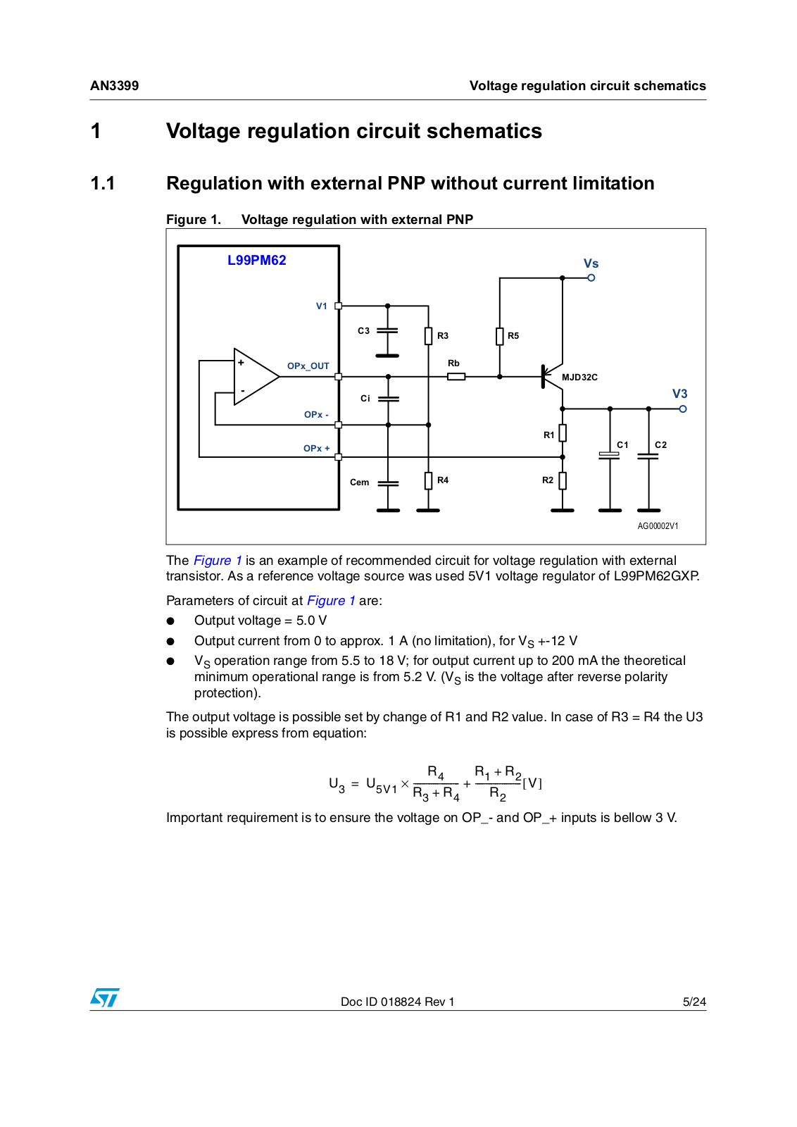
Figure 1. Voltage regulation with external PNP

/ 30


9V


9


&

5

5


23[B287

5E


0-' &


&L


9


23[


5


23[


&

&


&HP

5

5


$* 9

The Figure 1 is an example of recommended circuit for voltage regulation with external transistor. As a reference voltage source was used 5V1 voltage regulator of L99PM62GXP.

Parameters of circuit at Figure 1 are:

Output voltage = 5.0 V

Output current from 0 to approx. 1 A (no limitation), for VS +-12 V

VS operation range from 5.5 to 18 V; for output current up to 200 mA the theoretical minimum operational range is from 5.2 V. (VS is the voltage after reverse polarity protection).

The output voltage is possible set by change of R1 and R2 value. In case of R3 = R4 the U3 is possible express from equation:

U3

= U5V1

R4

R1 + R2

[ V]

× --------------------

+ --------------------


R3 + R4

R2


Important requirement is to ensure the voltage on OP_and OP_+ inputs is bellow 3 V.

Doc ID 018824 Rev 1

5/24

Voltage regulation circuit schematics

AN3399


1.2Regulation with external NPN without current limitation

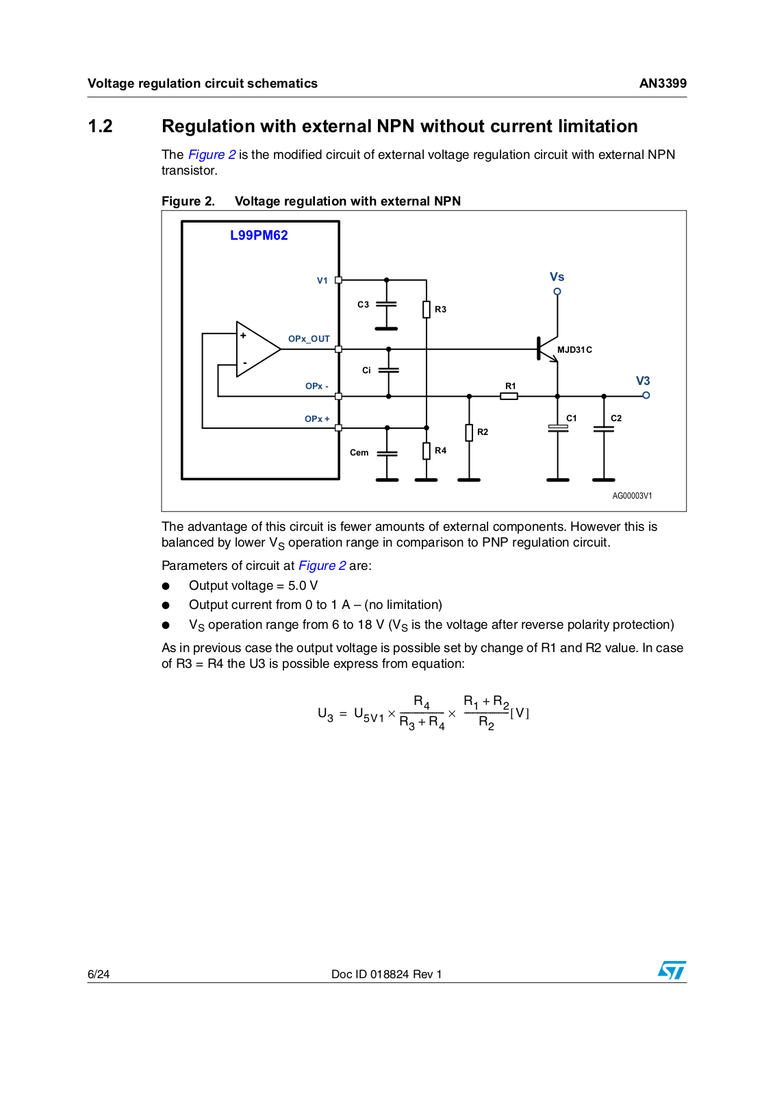
The Figure 2 is the modified circuit of external voltage regulation circuit with external NPN transistor.

Figure 2. Voltage regulation with external NPN

/ 30


9

9V


&

5


23[B287


0-' &


&L


9


23[

5


23[

&

&


5


&HP

5


$* 9

The advantage of this circuit is fewer amounts of external components. However this is balanced by lower VS operation range in comparison to PNP regulation circuit.

Parameters of circuit at Figure 2 are:

Output voltage = 5.0 V

Output current from 0 to 1 A – (no limitation)

VS operation range from 6 to 18 V (VS is the voltage after reverse polarity protection)

As in previous case the output voltage is possible set by change of R1 and R2 value. In case of R3 = R4 the U3 is possible express from equation:

U3

= U5V1

R4

×

R1 + R2

[ V]

× --------------------

--------------------


R3 + R4


R2


6/24

Doc ID 018824 Rev 1

ST AN3399 Application note

AN3399

Voltage regulation circuit schematics


1.3Voltage regulation and current limitation with external PNP

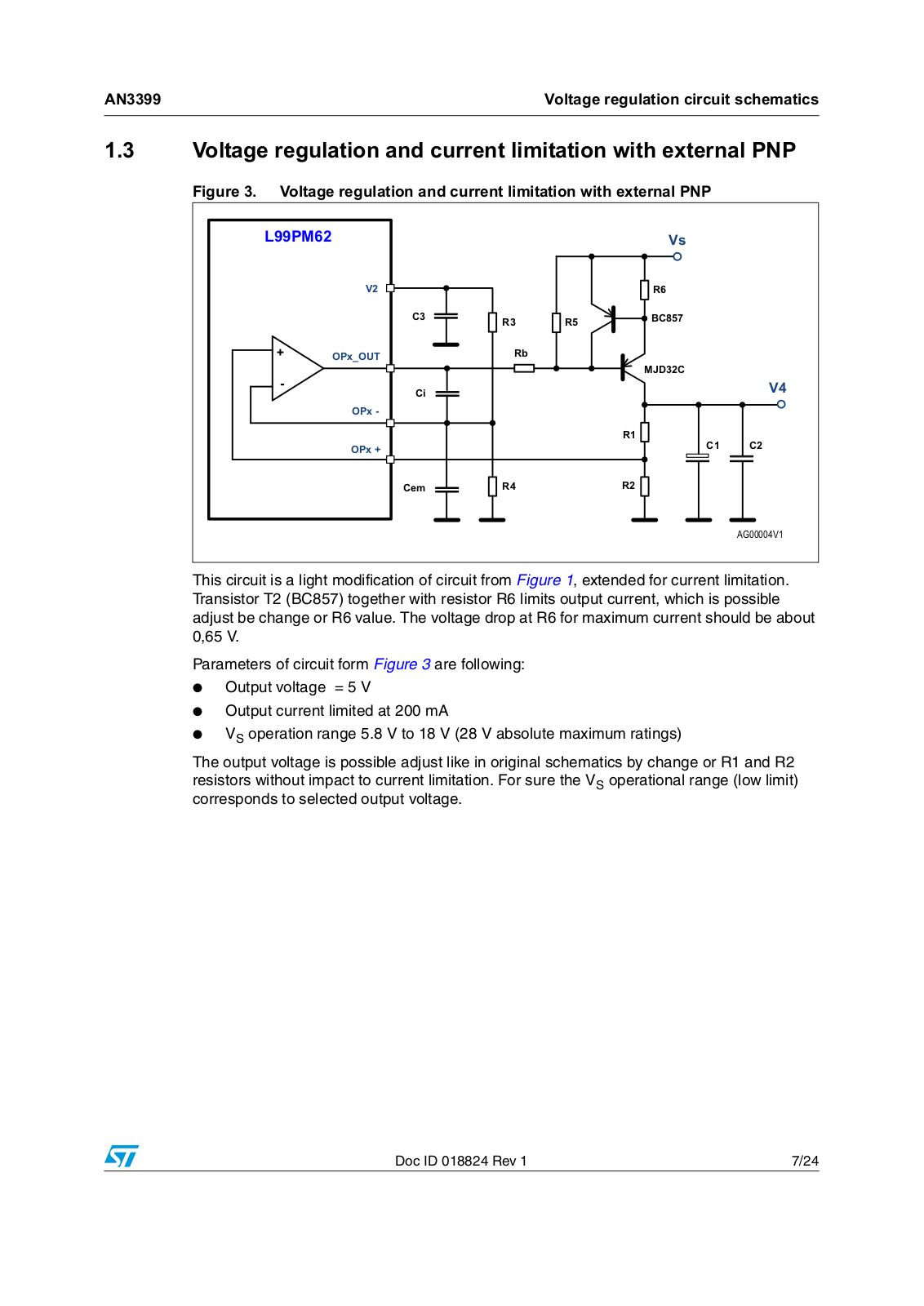
Figure 3. Voltage regulation and current limitation with external PNP

/ 30


9V


9


5


&

5

5

%&


23[B287

5E


0-' &


&L


9


23[


5


23[


&

&


&HP

5


5


$* 9

This circuit is a light modification of circuit from Figure 1, extended for current limitation. Transistor T2 (BC857) together with resistor R6 limits output current, which is possible adjust be change or R6 value. The voltage drop at R6 for maximum current should be about 0,65 V.

Parameters of circuit form Figure 3 are following:

Output voltage = 5 V

Output current limited at 200 mA

VS operation range 5.8 V to 18 V (28 V absolute maximum ratings)

The output voltage is possible adjust like in original schematics by change or R1 and R2 resistors without impact to current limitation. For sure the VS operational range (low limit) corresponds to selected output voltage.

Doc ID 018824 Rev 1

7/24

Voltage regulation circuit schematics

AN3399


1.4Voltage regulation and current limitation with external NPN

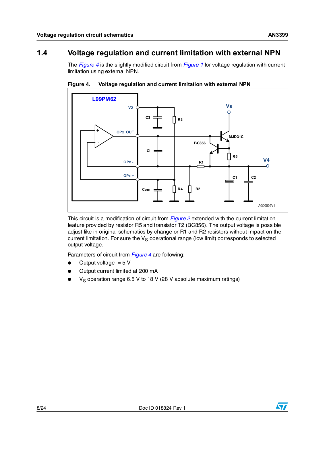
The Figure 4 is the slightly modified circuit from Figure 1 for voltage regulation with current limitation using external NPN.

Figure 4. Voltage regulation and current limitation with external NPN

/ 30


9V


9


&

5


23[B287


0-' &


%&


&L


5

9


23[


5


23[


&

&


&HP

5

5


$* 9

This circuit is a modification of circuit from Figure 2 extended with the current limitation feature provided by resistor R5 and transistor T2 (BC856). The output voltage is possible adjust like in original schematics by change or R1 and R2 resistors without impact on the current limitation. For sure the VS operational range (low limit) corresponds to selected output voltage.

Parameters of circuit from Figure 4 are following:

Output voltage = 5 V

Output current limited at 200 mA

VS operation range 6.5 V to 18 V (28 V absolute maximum ratings)

8/24

Doc ID 018824 Rev 1

Loading...
+ 16 hidden pages