

Page 1

Using the over-the-air bootloader with STM32W108 devices
Application (Up to 116 Kbytes)
OTA Bootloader (12 Kbytes)
Total of 128 Kbytes
1 Introduction
This document describes the over-the-air bootloader provided for STM32W108 devices. The
over-the-air (OTA) bootloader is a modified version of the USART-based bootloader
specified in application note AN3155 in order to deal with an 802.15.4 wireless
communication channel rather than a USART cable.
For more information, please refer to application note AN3155 USART protocol used in the
STM32 bootloader available from www.st.com/stm32w.
This document applies to the following STM32W108xx kits:
● STM32W108xx starter kit (part number: STM32W-SK)
● STM32W108xx extension kit (part number: STM32W-EXT)
● STM32W108xx low-cost RF control kit (part number: STM32W-RFCKIT).
AN3262
Application note
Overview
The purpose of the OTA bootloader application is to enable any node to receive a firmware
image over the air using the 802.15.4 interface and write it in Flash memory. In this context,
nodes willing to update their Flash contents with the new image are referred as bootloader
device nodes, while those in charge of transmitting the image over the air will be called
bootloader host nodes.
Figure 1. Memory layout
Figure 1 shows the memory layout of a bootloader device node; in order to be defined as
such it needs an OTA bootloader application image loaded right from the beginning at the
base of the STM32W Flash area (0x08000000) and any user application to run on the node
will have to sit on the top of the OTA bootloader. The bootloader takes 12 Kbytes leaving up
to 116 Kbytes free for user applications. At chip reset, control is passed to the bootloader
which in turn jumps to the application if present in Flash memory, or else it will just remain in
its main loop waiting for valid image packets sent by a host from the 802.15.4 RF interface. It
is also possible to override the default ‘jump to application’ behavior by forcing a bootloader
startup using a user-defined action (for example, a button press after reset). The bootloader
can eventually be started up from the application as well, but it depends on the application;
details related to bootloader activation criteria are out of the scope of the bootloader code.
March 2011 Doc ID 17845 Rev 2 1/27
www.st.com
Page 2

Contents AN3262
Contents
1 Introduction . . . . . . . . . . . . . . . . . . . . . . . . . . . . . . . . . . . . . . . . . . . . . . . . 1
2 Communication protocol . . . . . . . . . . . . . . . . . . . . . . . . . . . . . . . . . . . . . 3
3 Bootloader command set . . . . . . . . . . . . . . . . . . . . . . . . . . . . . . . . . . . . . 4
3.1 Get command . . . . . . . . . . . . . . . . . . . . . . . . . . . . . . . . . . . . . . . . . . . . . . . 5
3.2 Get Version & Read Protection Status command . . . . . . . . . . . . . . . . . . . 8
3.3 Get ID command . . . . . . . . . . . . . . . . . . . . . . . . . . . . . . . . . . . . . . . . . . . 11
3.4 Read Memory command . . . . . . . . . . . . . . . . . . . . . . . . . . . . . . . . . . . . . 13
3.5 Go command . . . . . . . . . . . . . . . . . . . . . . . . . . . . . . . . . . . . . . . . . . . . . . 16
3.6 Write Memory command . . . . . . . . . . . . . . . . . . . . . . . . . . . . . . . . . . . . . 19
3.7 Erase Memory command . . . . . . . . . . . . . . . . . . . . . . . . . . . . . . . . . . . . . 22
3.8 Write Incremental Memory command . . . . . . . . . . . . . . . . . . . . . . . . . . . 25
4 Revision history . . . . . . . . . . . . . . . . . . . . . . . . . . . . . . . . . . . . . . . . . . . 26
2/27 Doc ID 17845 Rev 2
Page 3

AN3262 Communication protocol
2 Communication protocol
A bootloading session consists of exchanges of commands codes and related data between
bootloader device (target) and host (transmitter) nodes. The protocol chosen for this
purpose is the same one as specified in application note AN3155 for STM32 USART
bootloader; its commands are a subset of those specified. The command set is further
described in the next section. The replacement of USART (universal
synchronous/asynchronous receiver/transmitter) with the 802.15.4 standard for point-topoint transmission of bits over the air, implies the deployment of all the well-known features
to cope with lossy channels such as CRC check, MAC level ACK detection and packet
retries in addition to all the functions that the (higher level) protocol provides to improve the
reliability of communication as described in the next section.
Commands and data are sent in the 802.15.4 payload which is variable in size according to
the specific information to be sent. 802.15.4 packets can be sent unicast and broadcast.
Broadcast packet are supported by a subset of commands and they are useful to discover
nodes in bootloader mode.
Figure 2 shows the selected format for a unicast 802.15.4 packet.
Figure 2. 802.15.4 packet format for unicast packet transmission
Frame
Control
(2 bytes)
0x61 0xCC
Sequence
Number
(1 byte)
Destination
Pan ID
(2 bytes)
Destination
EUI64
(8 bytes)
Source
EUI64
(8 bytes)
Payload
(variable)
FCS
(2 bytes)
Figure 3 shows the selected format for a broadcast 802.15.4 packet.
Figure 3. 802.15.4 packet format for broadcast packet transmission
Frame
Control
(2 bytes)
0x01 0xC8
Sequence
Number
(1 byte)
Destination
Pan ID
(2 bytes)
0xFFFF
Destination
Short
Address
(2 bytes)
0xFFFF
Source
EUI64
(8 bytes)
Payload
(variable)
FCS
(2 bytes)
The communication channel (between channels 11 and 26) and the PAN ID can be freely
chosen by the application before it launches the bootloader. In the case, where the
bootloader is not started by the application, it will run on a default channel (15) and default
bootloader PAN ID 0xB00B.
Doc ID 17845 Rev 2 3/27
Page 4

Bootloader command set AN3262
3 Bootloader command set
Ta bl e 1 lists commands supported by the OTA bootloader. A detailed command-by-
command protocol description follows.
Table 1. OTA bootloader commands
Command Command code Command description
(1)
G
ET
GET VERSION
ET ID
G
RASE 0x43 Erases memory pages of selected device.
E
W
RITE MEMORY 0x31 Writes up to 96 bytes in memory of selected device.
WRITE INCREMENTAL
MEMORY
(1)
(1)
(2)
READ MEMORY 0x11
O 0x21 Starts the code at a given location for a given device.
G
1. This command is supported by unicast and broadcast packets, while all the other are unicast only.
2. The WRITE INCREMENTAL MEMORY command is the only one not included in the original USART bootloader
command set.
0x00 Gets version number and list of commands allowed.
0x01
Gets bootloader version and Read Protection status of
the Flash memory.
0x02 Gets chip ID of device.
Writes up to 96 bytes in memory of selected device
0x36
incrementing next write address on device
automatically.
Reads up to 96 bytes of memory starting from a userspecified address.
Communication safety
All communications from the Host to the device are verified by:
● Checksum: received blocks of data bytes are XORed. A byte containing the computed
XOR of all previous bytes is added to the end of each communication (checksum byte).
By XORing all received bytes, data + checksum, the result at the end of the packet
must be 0x00.
● For each command, the host sends a byte and its complement (XOR = 0x00).
Each packet is either accepted (ACK) or discarded (NACK):
● ACK = 0x79
● NACK = 0x1F
4/27 Doc ID 17845 Rev 2
Page 5
AN3262 Bootloader command set
Ai14631
Send 0x00 + 0xFF
Start Get
Wait for ACK
or NACK
Receive the number of bytes
(version+commands)
Receive the bootloader version
Receive the supported commands
Wait for ACK
or NACK
End of Get
NACK
ACK
NACK
ACK
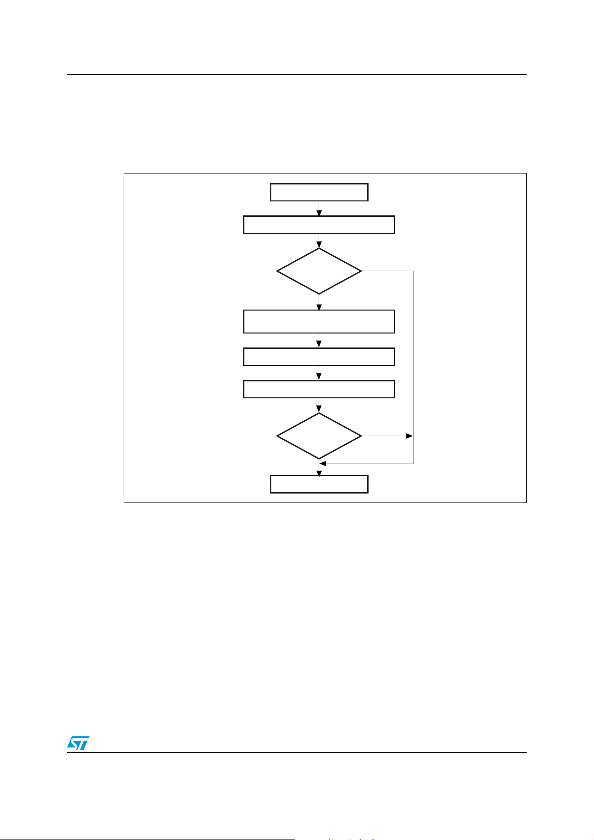
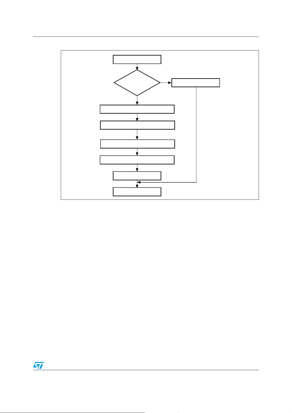
3.1 GET command
The GET command is used to determine the version of the bootloader and the supported
commands. When the bootloader receives the G
version and the supported command codes to the host as shown in the figures below.
ET command, it transmits the bootloader
Figure 4. G
ET command (host side)
Doc ID 17845 Rev 2 5/27
Page 6
Bootloader command set AN3262
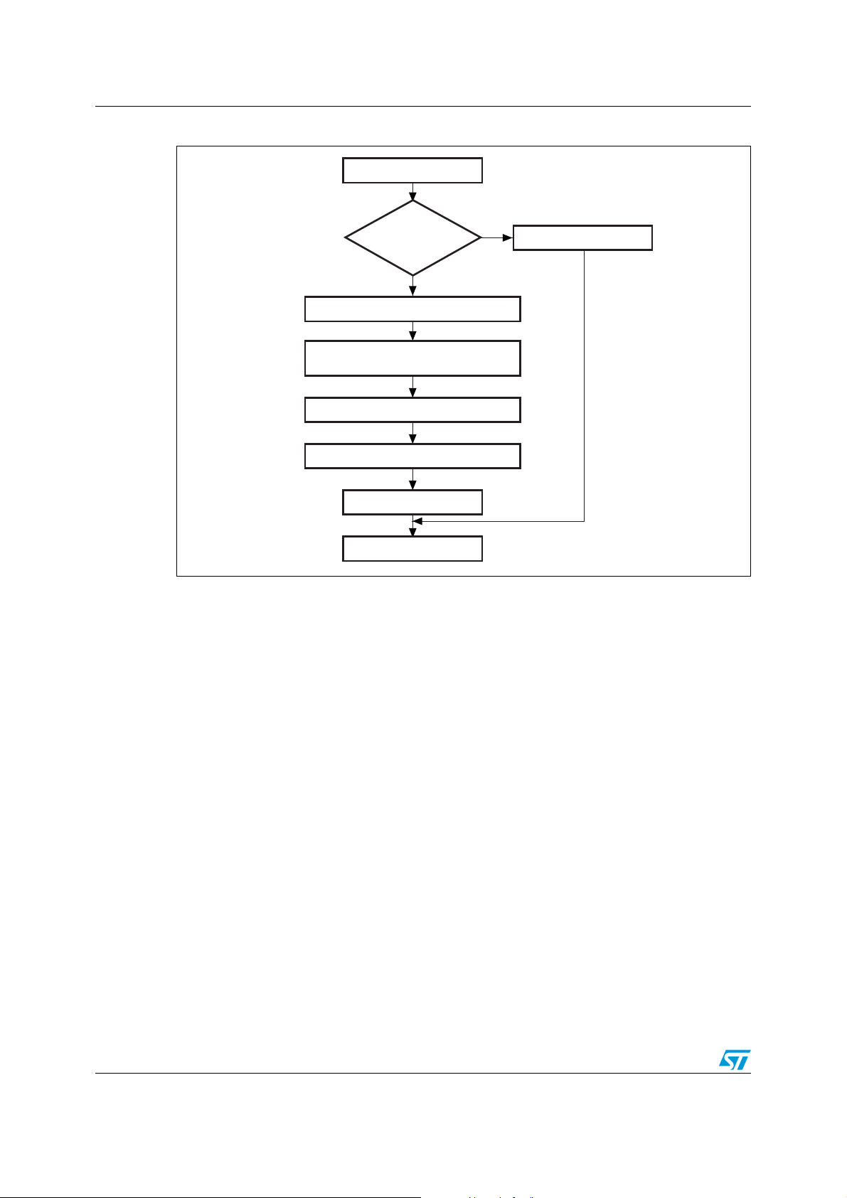
Ai14632
Send ACK byte
Start Get
Received
byte = 0x00+0xFF?
Send the number of bytes
(version+commands)
Send the bootloader version
Send the supported commands
End of Get
No
Ye s
Send NACK byte
Send ACK byte
Figure 5. GET command (device side)
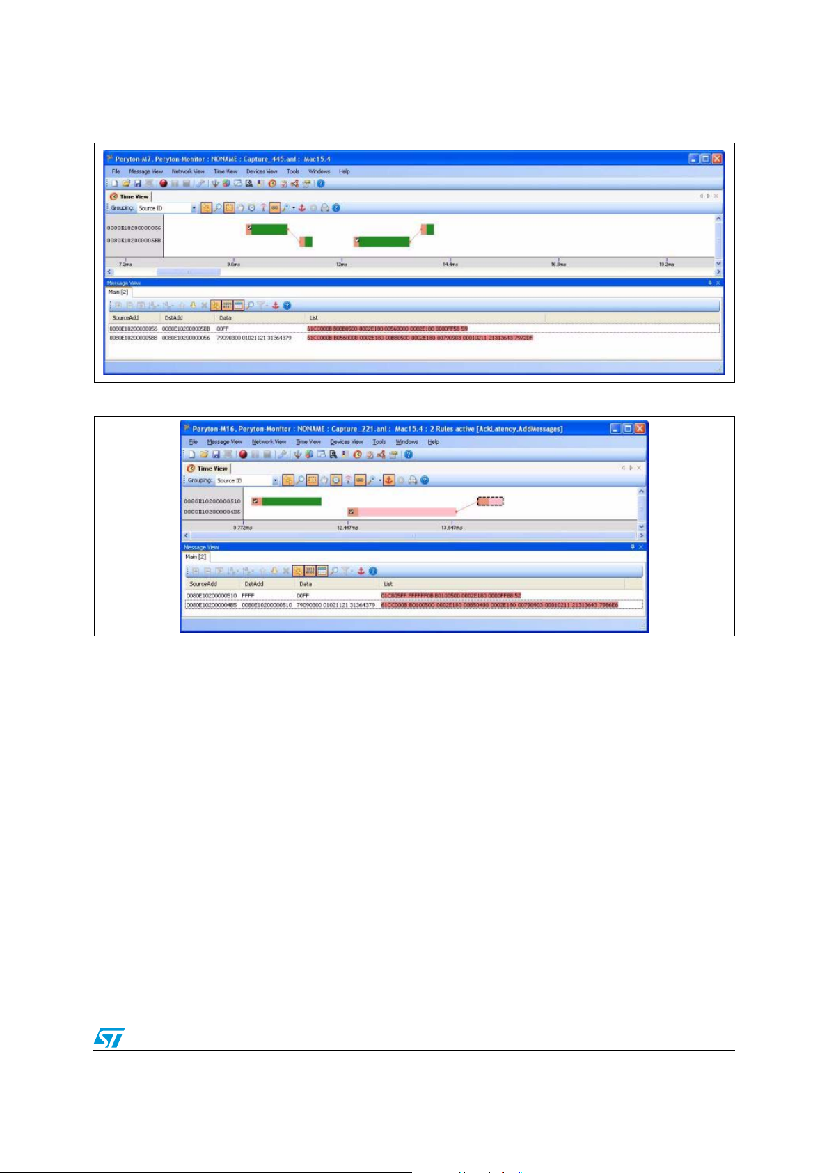
All information sent by the device starting from the first ACK/NACK to the last ACK/NACK is
contained inside a single 802.15.4 packet as shown in Figure 6.
The STM32 sends the following bytes:
Byte 1: ACK
Byte 2: N = 09 (the number of bytes to follow – 1)
(Does not include the current byte and ACKs.)
Byte 3: Bootloader version (0 < Version < 255)
Byte 4: 0x00 G
Byte 5: 0x01 G
Byte 6: 0x02 GET ID
Byte 7: 0x11 R
Byte 8: 0x21 G
Byte 9: 0x31 W
Byte 10: 0x43 E
Byte 11: 0x36 W
Last byte (15): ACK
ET command
ET VERSION; and
R
EAD PROTECTION STATUS
EAD MEMORY command
O command
RITE MEMORY command
RASE command
RITE MEMORY INCREMENTAL command
6/27 Doc ID 17845 Rev 2
Page 7
AN3262 Bootloader command set
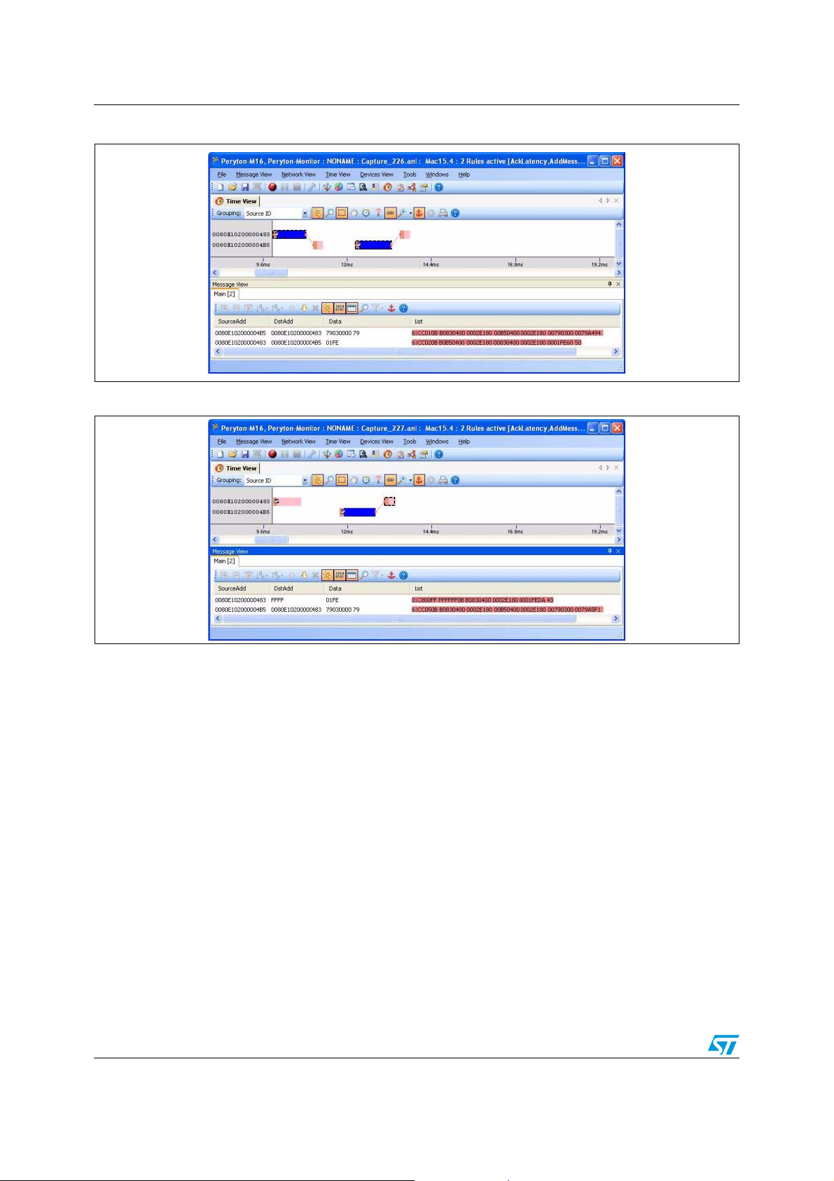
Figure 6. GET packet example (unicast)
Figure 7. G
ET packet example (broadcast)
Doc ID 17845 Rev 2 7/27
Page 8
Bootloader command set AN3262
Ai14633
Wait for ACK
or NACK
Receive the number of times the
read protection was disabled
Receive the bootloader version
Wait for ACK
or NACK
End of GV
(1)
NACK
ACK
Send 0x01+0xFE
Start GV
(1)
Receive the number of times the
read protection was enabled
NACK
ACK
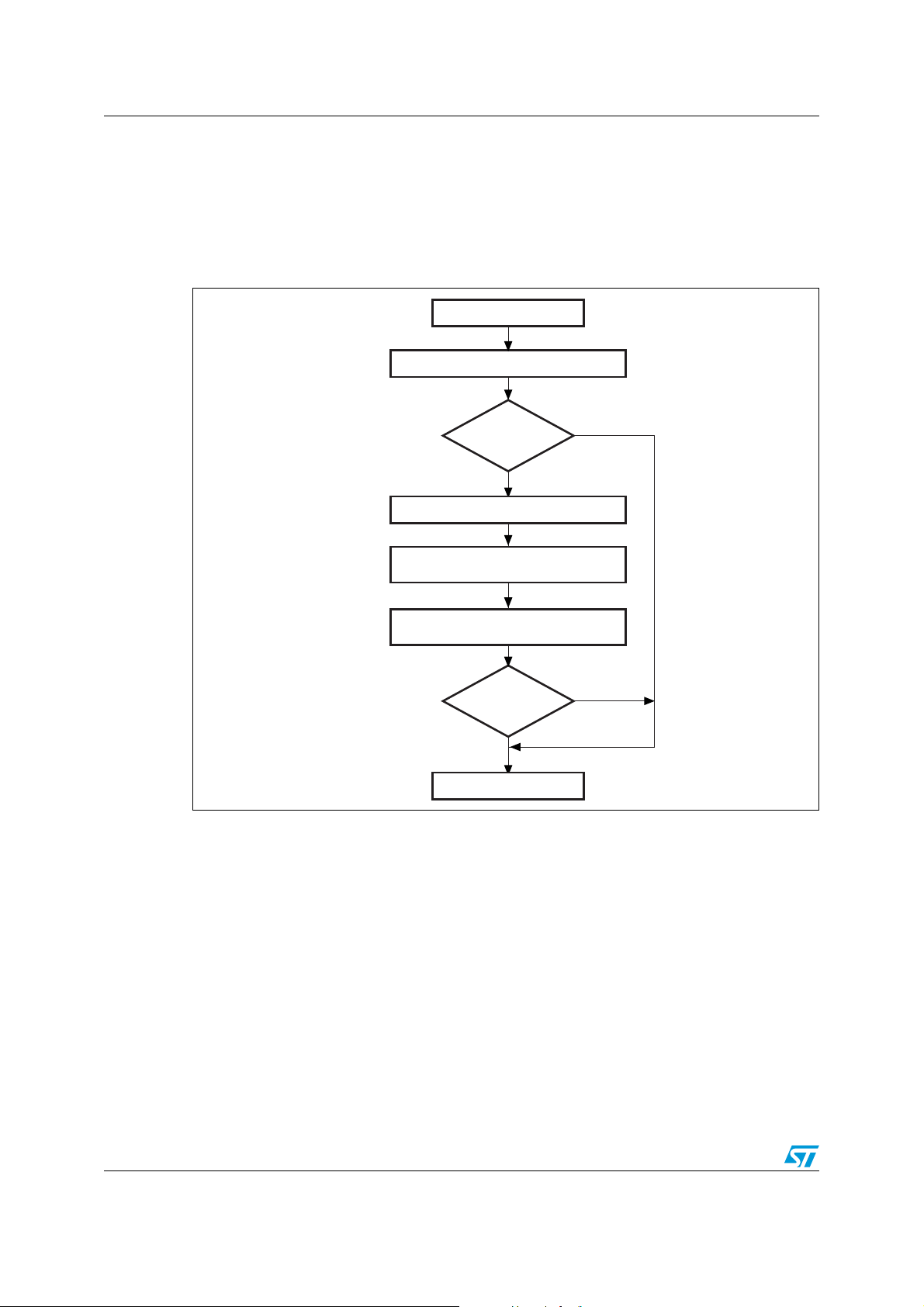
3.2 GET VERSION & READ PROTECTION STATUS command
The GET VERSION & READ PROTECTION STATUS command is used to get the bootloader
version and the read protection status. When the bootloader receives the command, it
transmits the information described below (version, read protection: number of times it was
enabled and disabled) to the host.
Figure 8. Get Version & Read Protection Status command: host side
1. GV = Get Version & Read Protection Status.
8/27 Doc ID 17845 Rev 2
Page 9
AN3262 Bootloader command set
Ai14634
Send ACK byte
Start GV
(1)
Received
byte = 0x01+0xFE?
Send the bootloader version
Option byte 2
End of GV
(1)
No
Ye s
Send NACK byte
Send ACK byte
Option byte 1
Figure 9. Get Version & Read Protection Status command: device side
1. GV = Get Version & Read Protection Status.
The STM32 device sends the following bytes:
Byte 1: ACK
Byte 2: Bootloader version (0 < Version ≤ 255)
Byte 3: Option byte 1: 0x00 to keep the compatibility with generic
Byte 4: Option byte 2: 0x00 to keep the compatibility with generic
Byte 5: ACK
bootloader protocol
bootloader protocol
Doc ID 17845 Rev 2 9/27
Page 10
Bootloader command set AN3262
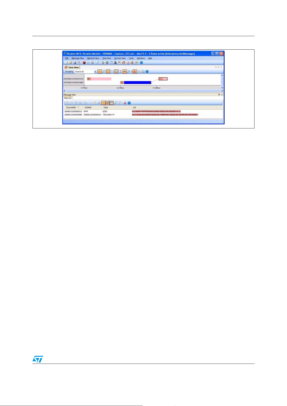
Figure 10. GET VERSION packet example (unicast)
Figure 11. G
ET VERSION packet example (broadcast)
10/27 Doc ID 17845 Rev 2
Page 11

AN3262 Bootloader command set
Ai14635
Wait for ACK
or NACK
Receive N = number of bytes – 1
Wait for ACK
or NACK
End of GID
(1)
NACK
ACK
Send 0x02+0xFD
Start GID
(1)
Receive PID
NACK
ACK
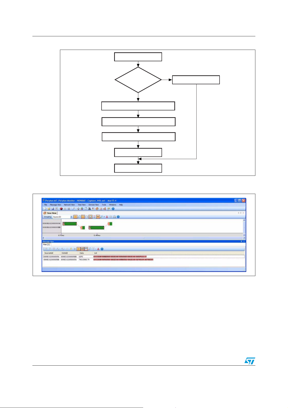
3.3 GET ID command
The GET ID command is used to get the version of the chip ID (identification). When the
bootloader receives the command, it transmits the device ID to the host.
The STM32 device sends the following bytes:
Byte 1: ACK
Byte 2: N = the number of bytes - 1
(N = 1 for STM32), except for current byte and ACKs.
Bytes 3-4: PID (Byte 3 = 0x09, Byte 4 = 0xA8)
Byte 5: ACK
All information sent by the device starting from the first ACK/NACK to the last ACK/NACK is
contained inside a single 802.15.4 packet as shown in Figure 14.
Figure 12. G
ET ID command (host side)
1. GID = Get ID command.
Doc ID 17845 Rev 2 11/27
Page 12
Bootloader command set AN3262
Ai14636
Send ACK byte
Start GID
(1)
Received
byte = 0x02+0xFD?
Send N = number of bytes – 1
End of GID
(1)
No
Ye s
Send NACK byte
Send ACK byte
Send product ID
Figure 13. GET ID command (device side)
1. GID = Get ID command.
Figure 14. GET ID packet example (unicast)
12/27 Doc ID 17845 Rev 2
Page 13
AN3262 Bootloader command set
Figure 15. GET ID packet example (broadcast)
3.4 READ MEMORY command
The READ MEMORY command reads data from any valid memory address in RAM, Flash
memory and the information block (System memory or option byte areas).
When the bootloader receives the R
application. After sending the ACK byte, the bootloader waits for an address (4 bytes, where
Byte 1 is the address MSB and Byte 4 is the LSB) and a checksum byte. Then it checks the
received address. If the address is valid and the checksum is correct, the bootloader
transmits an ACK byte, otherwise it transmits a NACK byte and aborts the command.
When the address is valid and the checksum is correct, the bootloader waits for the number
of bytes to be transmitted – 1 (N bytes) and for its complemented byte (checksum). If the
checksum is correct, it then transmits the needed data ((N + 1) bytes) to the application,
starting from the received address. If the checksum is not correct, it sends a NACK before
aborting the command.
The host sends bytes to the STM32 as follows:
Bytes 1-2: 0x11+0xEE
Wait for ACK
Bytes 3 to 6: Start address (Byte 3 is MSB and Byte 6 is LSB)
Byte 7: Checksum (XOR value of Bytes 3 to 6)
Wait for ACK
Byte 8: The number of bytes to be read – 1 (0 < N ≤ 95);
Byte 9: Checksum (XOR value (complement) of Byte 8)
EAD MEMORY command, it transmits the ACK byte to the
Doc ID 17845 Rev 2 13/27
Page 14

Bootloader command set AN3262
Ai14637
Wait for ACK
or NACK
Send the start address (4 bytes) with
checksum
Wait for ACK
or NACK
End of RM
(1)
NACK
ACK
Send 0x11+0xEE
Start RM
(1)
Send the number of bytes to be read (1 byte)
and a checksum (1 byte)
Wait for ACK
or NACK
Receive data from the BL
NACK
ACK
NACK
ACK
Figure 16. READ MEMORY command (host side)
1. RM = READ MEMORY command.
14/27 Doc ID 17845 Rev 2
Page 15

AN3262 Bootloader command set
Ai14638
ROP active
Receive the start address (4 bytes)
with checksum
Checksum OK?
End of RM
(1)
Start RM
(1)
Receive the number of bytes to be read (1 byte)
and a checksum (1 byte)
Address valid &
checksum OK?
Send data to the host
Received byte =
0x11+0xEE
Send ACK byte
Send ACK byte
Send ACK byte
Send NACK byte
No
Ye s
No
Ye s
No
Ye s
No
Ye s
Figure 17. READ MEMORY command (device side)
1. RM = READ MEMORY command.
The last ACK/NACK is sent before the data block to be read within the same 802.15.4
packet payload (while other ACK/NACKs are sent in independent packets).
Doc ID 17845 Rev 2 15/27
Page 16

Bootloader command set AN3262
Figure 18. READ MEMORY packet example
3.5 GO command
The GO command is used to execute the downloaded code or any other code by branching
to an address specified by the application. When the bootloader receives the G
it transmits the ACK byte to the application. After sending the ACK byte, the bootloader waits
for an address (4 bytes, where Byte 1 is the address MSB and Byte 4 is LSB) and a
checksum byte, then it checks the received address. If the address is valid and the
checksum is correct, the bootloader transmits an ACK byte; otherwise, it transmits a NACK
byte and aborts the command.
O command,
When the address is valid and the checksum is correct, the bootloader firmware performs
the following:
● It initializes the registers of the peripherals used by the bootloader to their default reset
values.
● It initializes the user application's main stack pointer.
● It jumps to the memory location programmed in the received ‘address + 4’ (which
corresponds to the address of the application's reset handler).
For example, if the received address is 0x0800 0000, the bootloader will jump to the
memory location programmed at address 0x0800 0004.
In general, the host should send the base address where the application to jump to is
programmed.
16/27 Doc ID 17845 Rev 2
Page 17

AN3262 Bootloader command set
Wait for ACK
or NACK
Send 0x21 + 0xDE
NACK
ACK
NACK
ACK
Start Go
End of EER
NACK
ACK
Wait for ACK
or NACK
Wait for ACK
or NACK
Ai14639b
Send the Start Address
(4 bytes) & Checksum
Figure 19. GO command (host side)
Note: 1 Valid addresses for the G
considered not valid and are NACKed by the device.
2 When an application is loaded into RAM and then a jump is made to it, the program must be
configured to run with an offset to avoid overlapping with the first RAM memory used by the
bootloader firmware.
3 The jump to the application works only if the user application correctly sets the vector table
to point to the application address.
O command are in RAM or Flash memory. All other addresses are
Doc ID 17845 Rev 2 17/27
Page 18

Bootloader command set AN3262
Ai14640b
Received bytes =
0x21+0xDE?
Start Go
ROP active
Send ACK byte
Send ACK byte
Receive the start address (4 bytes)
& checksum
Address valid &
checksum
OK?
Send ACK byte
Jump to user application
Send NACK byte
No
Ye s
No
Ye s
No
End of Go
Figure 20. GO command (device side)
The host sends the following bytes to the STM32 device:
Byte 1: 0x21
Byte 2: 0xDE
Wait for ACK
Bytes 3 to 6: Start address (Byte 3 is the MSB and Byte 6 is the LSB)
Byte 7: Checksum (XOR value of Bytes 3 to 6)
The second and third ACK/NACKs are sent by the device within the same 802.15.4 packet
while the first is sent independently.
18/27 Doc ID 17845 Rev 2
Page 19

AN3262 Bootloader command set
Figure 21. GO command example
3.6 WRITE MEMORY command
The WRITE MEMORY command writes data to any valid memory address (see note below) of
RAM, Flash memory or Option byte area.
When the bootloader receives the W
RITE MEMORY command, it transmits the ACK byte to
the application. After sending the ACK byte, the bootloader waits for an address (4 bytes,
where Byte 1 is the address MSB and Byte 4 is the LSB) and a checksum byte, it then
checks the received address. For the Option byte area, the start address must be the base
address of the Option byte area (see note) to prevent unwanted writing to this area.
Note: 1 Write operations to Flash memory/SRAM must be word (32-bit) aligned and data should be
in multiples of four bytes. If less data are written, the remaining bytes should be filled by
0xFF.
If the received address is valid and the checksum is correct, the bootloader transmits an
ACK byte; otherwise, it transmits a NACK byte and aborts the command. When the address
is valid and the checksum is correct, the bootloader:
● receives a byte (N) containing the number of data bytes to be received,
● receives the user data ((N + 1) bytes) and the checksum (XOR of N and of all data
bytes),
● programs the user data to memory starting from the received address,
● at the end of the command, if the write operation was successful, the bootloader
transmits the ACK byte; otherwise it transmits a NACK byte to the application and
aborts the command.
The maximum length of the block to be written for STM32W devices is 96 bytes.
If the W
RITE MEMORY command is issued to the Option byte area, all options are erased
before writing the new values.
Note: 1 When writing to the RAM, you should take care not to overlap the first RAM memory used by
the bootloader firmware.
2 No error is returned when performing write operations on write-protected sectors.
3 No error is returned when the start address is invalid.
Doc ID 17845 Rev 2 19/27
Page 20
Bootloader command set AN3262
Ai14641b
Wait for ACK
or NACK
Wait for ACK
or NACK
End of WM
(1)
NACK
ACK
Send 0x31+0xCE
Start WM
(1)
Wait for ACK
or NACK
Send the start address (4 bytes)
& checksum
Send the number of bytes to be written
(1 byte), the data (N + 1 bytes)
(2)
and checksum
NACK
ACK
NACK
ACK
Figure 22. WRITE MEMORY command (host side)
1. WM = WRITE MEMORY command.
2. N+1 should always be a multiple of 4.
20/27 Doc ID 17845 Rev 2
Page 21

AN3262 Bootloader command set
Ai14642d
ROP inactive?
Receive the start address (4 bytes) &
checksum
Flash memory
address?
No
Ye s
Start WM
(1)
Receive the number of bytes to be written
(1 byte), the data (N + 1 bytes)
(2)
and checksum
Checksum OK?
No
Ye s
Received byte =
0x31+0xCE?
Send ACK byte
Send ACK byte
Write the received data to Flash
memory from the start address
Send
ACK
byte
End of WM
(1)
No
Ye s
No
Ye s
Checksum OK?
No
Ye s
RAM address?
Write the received data to RAM
from the start address
Ye s
Ye s
Option
byte address?
Write the received data to
Option byte area from start address
Ye s
Ye s
Write the Keys for Option byte
area access
Send
NACK
byte
Send ACK byte
Figure 23. WRITE MEMORY command (device side)
1. WM = WRITE MEMORY command.
2. N+1 should always be a multiple of 4.
Doc ID 17845 Rev 2 21/27
Page 22

Bootloader command set AN3262
The host sends the following bytes to the STM32W device:
Byte 1: 0x31
Byte 2: 0xCE
Wait for ACK
Bytes 3 to 6: Start address (Byte 3 is the MSB and Byte 6 is the LSB)
Byte 7: Checksum (XOR value of Bytes 3 to 6)
Wait for ACK
Byte 8: Number of bytes to be received (0 < N ≤ 95)
N +1 data bytes (maximum of 96 bytes)
Byte 9: Checksum (XOR value of N, N+1 data bytes)
Figure 24. W
RITE MEMORY packet example
3.7 ERASE MEMORY command
The ERASE MEMORY command enables the host to erase Flash memory pages. When the
bootloader receives the E
After sending the ACK byte, the bootloader receives one byte (the number of pages to be
erased), the Flash memory page codes and a checksum byte. If the checksum is correct,
the bootloader erases the memory and sends an ACK byte to the host; otherwise, it sends a
NACK byte to the host and the command is aborted.
RASE MEMORY command, it transmits the ACK byte to the host.
E
RASE MEMORY command specifications:
● The bootloader receives one byte containing N, the number of pages to be erased – 1.
(For 0 ≤ N ≤115, N + 1 pages are erased.)
● The bootloader receives (N + 1) bytes, each byte containing a page number.
Note: No error is returned when performing erase operations on write-protected sectors.
22/27 Doc ID 17845 Rev 2
Page 23

AN3262 Bootloader command set
Ai14643c
Wait for ACK
or NACK
Wait for ACK
or NACK
End of ER
(1)
NACK
ACK
Send 0x43+0xBC
Start ER
(1)
Send the number of pages
to be erased (1 byte)
Send the page numbers
Send checksum
NACK
ACK
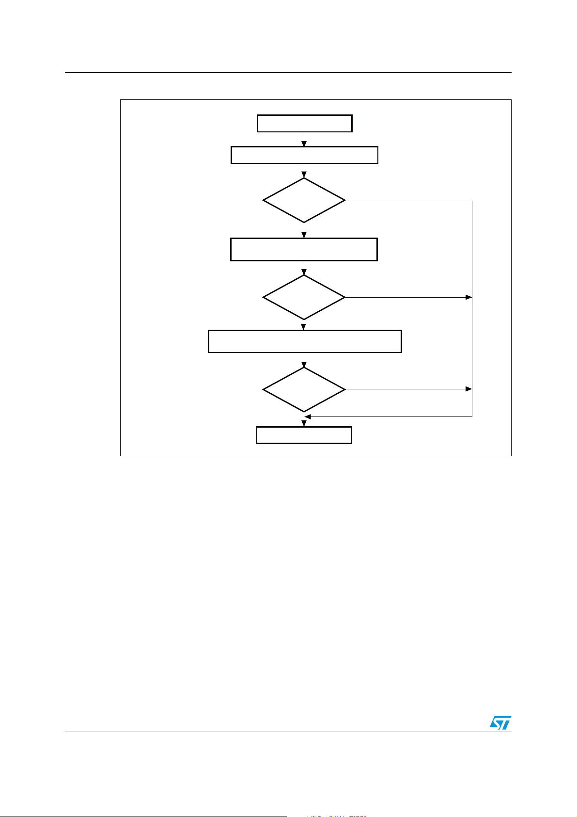
Figure 25. ERASE MEMORY command (host side)
1. ER = ERASE MEMORY command.
Doc ID 17845 Rev 2 23/27
Page 24
Bootloader command set AN3262
Ai14644c
ROP active
Receive the number of pages
to be erased (1 byte)
No
Ye s
Start ER
(1)
No
Received bytes =
0x43+0xBC?
Send ACK byte
Receive the page codes
Checksum
OK?
Send NACK byte
End of ER
(1)
No
Ye s
No
Ye s
Receive the checksum
Erase the corresponding pages
Send ACK byte
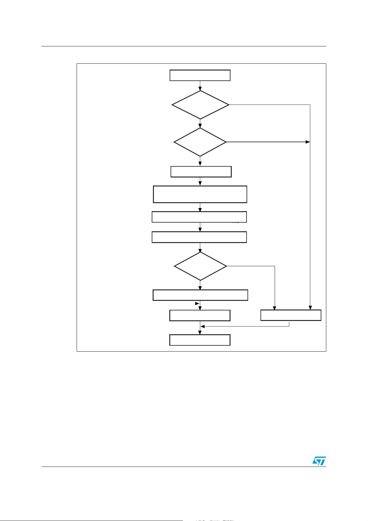
Figure 26. ERASE MEMORY command (device side)
1. ER = ERASE MEMORY command.
The host sends bytes to the STM32 as follows:
Byte 1: 0x43
Byte 2: 0xBC
Wait for ACK
Byte 3: Number of pages to be erased – 1
(0 ≤ N ≤ maximum number of pages)
Byte 4: N + 1 bytes (page numbers)
and then checksum (XOR value of N, N+1 bytes)
24/27 Doc ID 17845 Rev 2
Page 25
AN3262 Bootloader command set
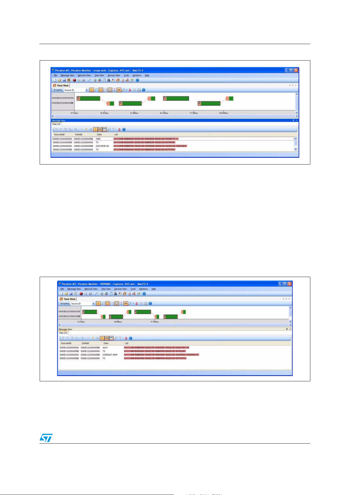
Figure 27. ERASE MEMORY packet example
3.8 WRITE INCREMENTAL MEMORY command
The WRITE INCREMENTAL MEMORY command has the same purpose of the WRITE MEMORY
command but can be used to save some bandwidth by avoiding having to transmit the write
address each time we wish to write a block. It only works when writing to consecutive
memory blocks. The device has a write pointer as an initial memory address for incremental
write operations. When the command is received, the device writes the command data in
memory and then increments the pointer by an amount of bytes equal to the write data
length. The write pointer update is also affected by the ordinary write command after which
the new address offset is the sum of the write address (provided as command parameter)
and the write data block length. The write pointer is initially set to the base of the application
address (0x08003000).
Figure 28. W
RITE INCREMENTAL MEMORY packet example
Doc ID 17845 Rev 2 25/27
Page 26

Revision history AN3262
4 Revision history
Table 2. Document revision history
Date Revision Changes
23-Aug-2010 1 Initial release.
04-Mar-2011 2
Updated STM32W website URL and added support for
STM32W108xx kits.
26/27 Doc ID 17845 Rev 2
Page 27

AN3262
Please Read Carefully:
Information in this document is provided solely in connection with ST products. STMicroelectronics NV and its subsidiaries (“ST”) reserve the
right to make changes, corrections, modifications or improvements, to this document, and the products and services described herein at any
time, without notice.
All ST products are sold pursuant to ST’s terms and conditions of sale.
Purchasers are solely responsible for the choice, selection and use of the ST products and services described herein, and ST assumes no
liability whatsoever relating to the choice, selection or use of the ST products and services described herein.
No license, express or implied, by estoppel or otherwise, to any intellectual property rights is granted under this document. If any part of this
document refers to any third party products or services it shall not be deemed a license grant by ST for the use of such third party products
or services, or any intellectual property contained therein or considered as a warranty covering the use in any manner whatsoever of such
third party products or services or any intellectual property contained therein.
UNLESS OTHERWISE SET FORTH IN ST’S TERMS AND CONDITIONS OF SALE ST DISCLAIMS ANY EXPRESS OR IMPLIED
WARRANTY WITH RESPECT TO THE USE AND/OR SALE OF ST PRODUCTS INCLUDING WITHOUT LIMITATION IMPLIED
WARRANTIES OF MERCHANTABILITY, FITNESS FOR A PARTICULAR PURPOSE (AND THEIR EQUIVALENTS UNDER THE LAWS
OF ANY JURISDICTION), OR INFRINGEMENT OF ANY PATENT, COPYRIGHT OR OTHER INTELLECTUAL PROPERTY RIGHT.
UNLESS EXPRESSLY APPROVED IN WRITING BY AN AUTHORIZED ST REPRESENTATIVE, ST PRODUCTS ARE NOT
RECOMMENDED, AUTHORIZED OR WARRANTED FOR USE IN MILITARY, AIR CRAFT, SPACE, LIFE SAVING, OR LIFE SUSTAINING
APPLICATIONS, NOR IN PRODUCTS OR SYSTEMS WHERE FAILURE OR MALFUNCTION MAY RESULT IN PERSONAL INJURY,
DEATH, OR SEVERE PROPERTY OR ENVIRONMENTAL DAMAGE. ST PRODUCTS WHICH ARE NOT SPECIFIED AS "AUTOMOTIVE
GRADE" MAY ONLY BE USED IN AUTOMOTIVE APPLICATIONS AT USER’S OWN RISK.
Resale of ST products with provisions different from the statements and/or technical features set forth in this document shall immediately void
any warranty granted by ST for the ST product or service described herein and shall not create or extend in any manner whatsoever, any
liability of ST.
ST and the ST logo are trademarks or registered trademarks of ST in various countries.
Information in this document supersedes and replaces all information previously supplied.
The ST logo is a registered trademark of STMicroelectronics. All other names are the property of their respective owners.
© 2011 STMicroelectronics - All rights reserved
STMicroelectronics group of companies
Australia - Belgium - Brazil - Canada - China - Czech Republic - Finland - France - Germany - Hong Kong - India - Israel - Italy - Japan -
Malaysia - Malta - Morocco - Philippines - Singapore - Spain - Sweden - Switzerland - United Kingdom - United States of America
www.st.com
Doc ID 17845 Rev 2 27/27
 Loading...